EP1074195B1 - Buckle - Google Patents
Buckle Download PDFInfo
- Publication number
- EP1074195B1 EP1074195B1 EP99916051A EP99916051A EP1074195B1 EP 1074195 B1 EP1074195 B1 EP 1074195B1 EP 99916051 A EP99916051 A EP 99916051A EP 99916051 A EP99916051 A EP 99916051A EP 1074195 B1 EP1074195 B1 EP 1074195B1
- Authority
- EP
- European Patent Office
- Prior art keywords
- buckle
- band
- section
- engagement
- edge
- Prior art date
- Legal status (The legal status is an assumption and is not a legal conclusion. Google has not performed a legal analysis and makes no representation as to the accuracy of the status listed.)
- Expired - Lifetime
Links
- 210000000078 claw Anatomy 0.000 claims abstract description 30
- 238000003780 insertion Methods 0.000 claims description 17
- 230000037431 insertion Effects 0.000 claims description 17
- 229920003002 synthetic resin Polymers 0.000 claims description 15
- 239000000057 synthetic resin Substances 0.000 claims description 15
- 238000005266 casting Methods 0.000 claims description 4
- 230000002093 peripheral effect Effects 0.000 description 13
- 239000000463 material Substances 0.000 description 8
- 230000000994 depressogenic effect Effects 0.000 description 7
- -1 polyethylene Polymers 0.000 description 5
- 238000004519 manufacturing process Methods 0.000 description 4
- 230000007246 mechanism Effects 0.000 description 4
- 230000000149 penetrating effect Effects 0.000 description 4
- 229920006324 polyoxymethylene Polymers 0.000 description 4
- 238000005516 engineering process Methods 0.000 description 3
- 239000011148 porous material Substances 0.000 description 3
- 229920001875 Ebonite Polymers 0.000 description 2
- 229930040373 Paraformaldehyde Natural products 0.000 description 2
- 229930182556 Polyacetal Natural products 0.000 description 2
- 239000004952 Polyamide Substances 0.000 description 2
- 239000004698 Polyethylene Substances 0.000 description 2
- 238000010276 construction Methods 0.000 description 2
- 229920002647 polyamide Polymers 0.000 description 2
- 229920000515 polycarbonate Polymers 0.000 description 2
- 239000004417 polycarbonate Substances 0.000 description 2
- 229920000573 polyethylene Polymers 0.000 description 2
- 229920000915 polyvinyl chloride Polymers 0.000 description 2
- 239000004800 polyvinyl chloride Substances 0.000 description 2
- 235000001674 Agaricus brunnescens Nutrition 0.000 description 1
- 239000004743 Polypropylene Substances 0.000 description 1
- 230000007547 defect Effects 0.000 description 1
- 230000000881 depressing effect Effects 0.000 description 1
- 230000000694 effects Effects 0.000 description 1
- 230000007257 malfunction Effects 0.000 description 1
- 229920001155 polypropylene Polymers 0.000 description 1
- 230000001681 protective effect Effects 0.000 description 1
- 230000003014 reinforcing effect Effects 0.000 description 1
- 238000000926 separation method Methods 0.000 description 1
- 230000035939 shock Effects 0.000 description 1
- 239000007787 solid Substances 0.000 description 1
- 239000013585 weight reducing agent Substances 0.000 description 1
Images


Classifications
-
- A—HUMAN NECESSITIES
- A44—HABERDASHERY; JEWELLERY
- A44B—BUTTONS, PINS, BUCKLES, SLIDE FASTENERS, OR THE LIKE
- A44B11/00—Buckles; Similar fasteners for interconnecting straps or the like, e.g. for safety belts
- A44B11/25—Buckles; Similar fasteners for interconnecting straps or the like, e.g. for safety belts with two or more separable parts
-
- A—HUMAN NECESSITIES
- A42—HEADWEAR
- A42B—HATS; HEAD COVERINGS
- A42B3/00—Helmets; Helmet covers ; Other protective head coverings
- A42B3/04—Parts, details or accessories of helmets
- A42B3/10—Linings
- A42B3/14—Suspension devices
- A42B3/145—Size adjustment devices
-
- A—HUMAN NECESSITIES
- A41—WEARING APPAREL
- A41F—GARMENT FASTENINGS; SUSPENDERS
- A41F1/00—Fastening devices specially adapted for garments
- A41F1/008—Adjustable fasteners comprising a track and a slide member
-
- A—HUMAN NECESSITIES
- A44—HABERDASHERY; JEWELLERY
- A44B—BUTTONS, PINS, BUCKLES, SLIDE FASTENERS, OR THE LIKE
- A44B11/00—Buckles; Similar fasteners for interconnecting straps or the like, e.g. for safety belts
- A44B11/02—Buckles; Similar fasteners for interconnecting straps or the like, e.g. for safety belts frictionally engaging surface of straps
- A44B11/06—Buckles; Similar fasteners for interconnecting straps or the like, e.g. for safety belts frictionally engaging surface of straps with clamping devices
-
- A—HUMAN NECESSITIES
- A44—HABERDASHERY; JEWELLERY
- A44B—BUTTONS, PINS, BUCKLES, SLIDE FASTENERS, OR THE LIKE
- A44B11/00—Buckles; Similar fasteners for interconnecting straps or the like, e.g. for safety belts
- A44B11/25—Buckles; Similar fasteners for interconnecting straps or the like, e.g. for safety belts with two or more separable parts
- A44B11/2592—Buckles; Similar fasteners for interconnecting straps or the like, e.g. for safety belts with two or more separable parts fastening by sliding in the main plane or a plane parallel to the main plane of the buckle
-
- A—HUMAN NECESSITIES
- A44—HABERDASHERY; JEWELLERY
- A44B—BUTTONS, PINS, BUCKLES, SLIDE FASTENERS, OR THE LIKE
- A44B11/00—Buckles; Similar fasteners for interconnecting straps or the like, e.g. for safety belts
- A44B11/20—Buckles; Similar fasteners for interconnecting straps or the like, e.g. for safety belts engaging holes or the like in strap
-
- Y—GENERAL TAGGING OF NEW TECHNOLOGICAL DEVELOPMENTS; GENERAL TAGGING OF CROSS-SECTIONAL TECHNOLOGIES SPANNING OVER SEVERAL SECTIONS OF THE IPC; TECHNICAL SUBJECTS COVERED BY FORMER USPC CROSS-REFERENCE ART COLLECTIONS [XRACs] AND DIGESTS
- Y10—TECHNICAL SUBJECTS COVERED BY FORMER USPC
- Y10T—TECHNICAL SUBJECTS COVERED BY FORMER US CLASSIFICATION
- Y10T24/00—Buckles, buttons, clasps, etc.
- Y10T24/14—Bale and package ties, hose clamps
- Y10T24/1498—Plastic band
Definitions
- the present invention can be used for providing a band (or a belt) having a buckle at its joint edge section, and more specifically for providing a band used as a head band for a helmet, a watch band, a band for trousers or a skirt, or a band for shoes or a bug.
- the present invention relates to a buckle for locking a band having an engagement groove, and more specifically to a buckle for a band or a belt such as a head band for a helmet, a watch band, a band for trousers or a skirt, or a band for shoes or a bug.
- a head band for a helmet is set around a head of a wearer and plays a role for locking the helmet to the head.
- Fig. 3 shows an ordinary helmet 1 for working, and is a perspective view showing a cap body 2 penetrating a cap body 2 and an internal setting body 4 penetrating a liner 3 adhered thereto for absorbing shock.
- the setting body 4 comprises a cross-like hammock 5, a head band 10 connected in a circular form, and a jaw strap 6, and this setting body 4 is set via brackets 7, 7 to the cap 2 to form the helmet 1.
- a peripheral length of the head band 10 for adjusting the size to the size of the wearer's head.
- a number of small projections 8, 8 ... are provided at an even space in one edge section of the head band 10, while small holes engaging with the small projections 8, 8 ... respectively are provided in the longitudinal direction of the head band 10, and the peripheral length can be adjusted by engaging the projections in the small holes appropriately.
- a size-adjustable band employing the pinion rack system therein (Refer to Japanese Patent Laid-Open Publication No. HEI 8-27613 ), or a head band for a helmet in which a worm screw mechanism is incorporated on the head band for enabling fine adjustment (Refer to Japanese Patent Laid-Open Publication No. HEI 7-293515 ) is available.
- the head band adjustment mechanisms have, however, the defect that, as the construction becomes more complicated, the weight of the helmet disadvantageously increases.
- GB-A-1 229 320 relates to a headband for use with personal protective equipment, the headband having flexible end portions which overlap forming an inner end portion and an outer end portion, the inner and outer end portions being provided with interlocking means which will permit the end portions to slide on one another to reduce the effective size of the headband whilst the headband is on the wearer's head and which will hold the end portions in engagement once the headband fits the wearer's head and the inner end portion is pressed against the outer end portion by the wearer's head, and the headband also including means for disengaging or separating the interlocking means on the end portions after the headband has been fitted on to the wearer's head thereby to permit the headband to be removed from the wearer's head.
- US 5,687,455 discloses a releasable fastener comprising a pliable elongated body member having a head end opposite a tail end, a lower body surface substantially parallel to an upper body surface, and a pair of substantially parallel side body surfaces, said side body surface being substantially perpendicular to said upper and lower body surfaces, said side body surfaces connecting said upper body surface to said lower body surface, said upper body surface containing a plurality of tooth members; a buckle member attached to said head end of said body member, said buckle member having a top buckle surface substantially parallel to a bottom buckle surface, said top and bottom buckle surfaces being substantially parallel to said upper and lower body surfaces, said buckle member also having a pair of substantially parallel sidewalls, said sidewalls being substantially perpendicular to said top and bottom buckle surfaces, said sidewalls connecting said top buckle surface to said bottom buckle surface, said top buckle surface, said bottom buckle surface, and said sidewalls being positioned to define a buckle channel substantially parallel to said body member, said buckle channel having an open body end and an open
- an intermediate catch is provided in the middle of the watch band so that the wearer can set the band or remove it with one hand by operating the catch with claws of finger tips.
- the work for loading on or off a watch with the intermediate catch is difficult for a person with short claws or a person with a weak power, and improvement of the intermediate catch will result in complication of its mechanism and structure.
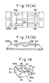
- Fig. 16 is a perspective view showing a representative buckle of this type.
- a buckle body 51 comprises a bottom plate 52 and side plates 53, 53 and has a substantially 3 - shaped cross section.
- Shaft 54 is spanned over the side plates 53, 53 with a cover piece 55 attached to the shaft 54.
- An edge 55A of the cover piece 55 is biased by a coil spring 56 to the bottom plate 52, and the other edge 55B of the cover piece 55 is used as a section for pressing.
- the buckle has a hole 57 or the like, which is used for attaching the buckle to a basic body of a bug, shoes, or various types of bands.
- engagement grooves each having a cross section like saw teeth and extending in the longitudinal direction are provided side by side, and the band is inserted into a space formed between the buckle body 51 and the cover piece 55.
- the band when the band is passed through the space, the band pushed the cover piece 55 upward against a springing force of the coil spring 56, and when insertion of the band is stopped at a desired fastening position, and an edge 55A of the cover piece 55 hooks in the engagement groove of the band, and movement of the band in the pulling-off direction is limited.
- the other edge 55B of the cover piece 55 When pulling off the band, the other edge 55B of the cover piece 55 is pushed down to the buckle body 51, and with this operation the other edge 55B is raised from the engagement groove of the band, thus the band being disengaged from the buckle.
- the conventional type of buckles have many components, so that the work for assembling the buckles are time-consuming and complicated, and in addition the buckles are metallic, so that the weight is heavy. Therefore such types of buckles can not satisfy the current demands for weight reduction.
- the mechanism for releasing the engagement between the buckle and the band by pressing from upside of the buckle body to the bottom plate is employed, and because of this structural feature, sometimes the band may be disengaged from the buckle due to unexpected contact of the buckle to something.
- the band has a protruding section for engagement at its one edge section and a recessed section also for engagement at the other edge section thereof, and is connected into a circular form by engaging the two sections for engagement and sliding the two edge sections to adjust its peripheral length.
- the protruding section for engagement is hooked in the recessed section for engagement, the other edge section can freely moves forward against the one edge section, but can not move backward, and a pair of hooking sections, with which the wearer can pull up the two edge sections with fingers of a hand, are provided at the two edge sections on a top surface of the band.
- the band has a groove for engagement at its one edge section and a claw for engagement at the other edge section, and is set into a circular form by engaging the engagement groove with the engagement claw and sliding the two edge sections of the band for adjusting the peripheral length.
- a resilient piece having the engagement claw is provided in parallel to the other edge section, and when the engagement claw is hooked in the engagement groove, the one edge section can freely moved forward against the other edge section, but can not move backward.
- the engagement can be disengaged from the engagement groove by operating the resilient piece, and the resilient piece is made from a material harder than the material for the two edge sections of the band.
- the buckle made from synthetic resin according to the present invention has a buckle body and an operation plate.
- the buckle body comprises a bottom plate, a ceiling frame opposite to the bottom plate and two side plates connecting the bottom plate and the ceiling frame to each other, and the buckle body has a space for insertion of a band with an engagement groove.
- the operation plate is provided inside the ceiling frame in the horizontal position and has an engagement claw for engagement with the engagement groove of the band on a bottom surface of its one edge and a top surface at the other edge used as a pressed section.
- Fig. 1(a) is a perspective view showing a state where two edge sections of a head band 10 are engaged with each other
- Fig. 1(b) is a longitudinal side view showing the same in the peripheral direction.
- an edge section having a protruding section for engagement is described as one edge section 12A
- a section with a recessed section for engagement is described as the other edge section 12B.
- a slide guide 14 having a looped portion is provided in the one edge section 12A which makes the other edge section 12B possible to insert easily therein or to prevent, and a claw-shaped protruding engagement section 16A is formed inside a stop ring 15 of the slide guide 14 as shown in Fig. 1(b) .
- a recessed engagement section 16B having a sawtoothed cross section is provided on a top surface of the other edge section 12B.
- the two engagement sections 16A, 16B are engaged with each other by sliding the two edge sections 12A, 12B, and the head band 10 is set to a circular form by adjusting the length thereof to that appropriate for the wearer.
- the claw-formed engagement protruding section 16A is hooked in the recessed engagement section 16B having a sawtoothed cross section, the other edge section 12B can freely move forward against the one edge section 12A, but can not move backward.
- a hooking section 20B is provided in the protruding form at the back of the recessed engagement section 16B on a top surface thereof.
- the hooking section 20B is required only to have a size and a form enough to be gripped by finger tips. Therefore, in addition to the semi-cylindrical forms shown in the figure, the hooking section may have a cylindrical or a rectangular column form. Further a through-hole 22 penetrating from an outer surface to an inner surface of the head band 10 as shown in Fig. 2(a) may be provided, or a hinge 24 supported by a pin 23 as a fulcrum as shown in Fig. 2(b) may be used.
- the stop ring 15 of the slide guide 14 protruding slightly from an outer surface of the one edge section 12A is provided at the one edge section 12A, so that the slide guide 14 can be used as a hooking section 20A for the one edge section 12A.
- the slide guide 14 is not always required, and for the head band 10 not having a portion like the hooking section 20A for the slide guide 14, an independent hooking section 20A may be provided also at the one edge section 12A.
- a projection 26 as the hooking section 20A may be provided at the one edge section 12A.
- the head band 10 is fabricated with such materials as polyvinyl chloride, polyethylene, other flexible synthetic resins, or hard rubber. In this step, it is preferable to previously form a curved surface matching a periphery of the wearer's head on the head band 10.
- the head band 10 has the configuration as described above, so that, by hooking finger tips of a hand in the stop ring 15 as the hooking section 20A and the hooking section 20B, and by pulling them closer to each other, the other edge section 12B goes into the slide guide 14 with the engagement sections 16A and 16B rubbing each other, thus a peripheral length of the head band 10 being adjusted to the required length.
- the present invention can be applied to a head band with the other edge section 12B of the head band 10 allowable to move only in one direction to or away from the one edge section 12A when the two engagement sections are engaged with each other by providing the pair of hooking sections 20A, 20B described above thereon.
- the size can be adjusted only with finger tips of one hand when the head band is set of a wearer's head. Therefore, with this head band, it is possible to quickly, easily, and accurately load on or off the helmet.
- the production cost is low with weight increase of the helmet suppressed.
- a head band is described below.
- a direction in which each edge section advances when two edge sections of the head band are engaged is described as forward direction, and a direction in which each edge section moves back is described as backward direction.
- Fig. 4 is a partial front view showing a state in which two edge sections of a head band 110 are separated from each other
- Fig. 5 is a front view showing a state in which the two edge sections of the head band 110 are engaged with each other.
- an engagement groove 114A having a sawtoothed cross section is formed on an outer surface of an one edge section 112A shown in Fig. 4(a) .
- a hooking section 116A protruding therefrom and having a hook-like front section.
- the hooking section 116A is required only to have the size and form allowing hooking of the wearer's finger tips therein. Therefore, in addition to the configuration shown in the figure, the hooking section 116A may have a form of cylindrical or semi- cylindrical column. Further a through-hole penetrating the head band from its outer surface to its inner surface may be provided.
- a hood 118 Provided on the outer surface of the other edge section 112B of the head band shown in Fig. 4B is a hood 118.
- the hood 118 has a top wall 118a expanding to the outer peripheral side of the head band as shown in Fig. 6 being the perspective view, and has openings in the front and rear sections, and the one edge section 112A of the head band can be passed through the openings.
- On a pair of side walls 118b, 118b constituting the hood 118 are provided open windows 118c, 118c, in which a push button 120 described hereinafter can be engaged with a certain degree of allowance.
- a rear edge section (the left edge section in Fig. 6 ) 118d of the top wall 118a is used as a hooking section 116B which is to be provided at the other edge section 112B.
- the hood is not essential in this invention, and therefore in the head band 110 not equipped with the hooking section 116 B like the rear edge section 118b of the top wall 118a, it is preferable to provide a separated hooking section 116B also at the other edge section 112B.
- band holders 117 are provided at the back of the hood 118 on the outer surface of the other edge section 112B along upper and lower rims of the other edge section 112B. It is preferable that each of the band holders 117 comprises a short shaft section and a head section having a diameter larger than that of this shaft section and has the so-called mushroom form.
- the mushroom-shaped band holder 117 is especially advantageous in the point that the one edge section 112A can be held and fixed only by pressing it with a finger tip.
- Fig. 7 is a perspective view showing the other edge section 112B seen from the bottom plate side.
- a space 122 Inside of the hood 118 is a space 122 in which the engagement section 124 described in detail below is accommodated, and stop pins 123, 123 are provided in the vertical position from the partially raised bottom surface 121 of the band.
- Fig. 8 is a perspective view showing the engagement section 124 accommodated in the space 122 inside the hood 118
- Fig. 9 is a longitudinal side view of the engagement section 124.
- the engagement section 124 mainly comprises a bottom wall section 126 and a head wall section 128 opposite to each other and two side wall sections 130, 130 also opposite to each other, and an insertion space 131 into which the one edge section 112A of the head band is inserted is defined by these four wall sections.
- a resilient piece 134 is provided on the head wall section 128 by forming a ⁇ - shaped slit 132, and an engagement claw 114B is provided in the protruding state on an inner wall of this resilient piece 134 at its head section.
- the resilient piece 134 is provided in parallel to the bottom wall section 126, so that the engagement section 124 does not substantially protrude to the outer periphery of the other edge section 112B, which enables the compact structure.
- Side pores 136, 136 each communicating to the insertion space 131 are provided on the two side wall sections 130, 130, and push buttons 120, 120 are provided at the extended edges of the two side wall sections 130, 130 at positions opposite to the side pores 136, 136 respectively.
- the push buttons 120, 120 are elastically deformed inward to the insertion space 131 and contact side sections of the resilient piece 134, thus a tip of the resilient piece 134 being deformed outward from the insertion space 131.
- the push buttons 120 are provided at the extended edge of the side wall section 130, but the push buttons 120 may be provided at any positions on the conditions that the push buttons are facing to the side pores 136, and for instance, a portion of the side wall 118b of the hood 118 may be formed with a resilient body so that the portion can functions as the push button 120.
- the engagement section 124 can be formed into an integrated body by using such synthetic resin as polyacetal, polyoxymethylene, polyamide, polycarbonate. Especially it is necessary to form the resilient body 134 with any synthetic resin so that its free edge side (at which the engagement claw 114B is provided) can swing in the vertical direction. In contrast, as the head band 110 including the two edge sections 112A and 112B directly contact the wearer's head, it is desirable to fabricate it with such soft and flexible synthetic resin as polyvinyl chloride, polyethylene and polypropylene, or with hard rubber.
- the resilient piece 134 is made with a material relatively harder as compared to a material used for forming the two edge sections 112A and 112B of the head band.
- a synthetic resin material suited to each portion may be employed by forming the head band including the two edge sections 112A, 112B and the engagement section 124 including the resilient piece 134 as independent bodies respectively.
- the engagement section 124 is accommodated in the space 122 within the hood 118 and integrated with the other edge section 112B by engaging round holes 138, 138 provided at two sections on the bottom wall section 126 with the stop pins 123, 123.
- the head band 110 according to the present invention is set to a circular form by sliding the two edge sections 112A, 112B to hook the engagement claw 114B in the engagement groove 114A for adjusting the length of the head band 110 to that suited to the wearer.
- the head band 110 according to the present invention has the configuration as described above, when the wearer aligns the one edge section 112A with insertion holes on the hood 118 and pulls closer to each other the hooking section 116A of the one edge section 112A and a rear edge section 118d of the hood 118 as the hooking section 116B for the other edge section 112B with finger tips of a hand, the engagement groove 114A contacts the engagement claw 114B of the resilient piece 134, and the one edge section 112A advances raising the resilient piece 134, thus a peripheral length of the head band 110 being adjusted to the appropriate length.
- the push buttons 120, 120 protruding from the side walls 118b of the hood 118 are pressed inward with fingers.
- tip sections 120a of the push buttons 120, 120 contact side sections of the resilient piece 134 with the tip of the resilient piece 134 deformed outward from the insertion space 131.
- the engagement claw 114B is disengaged from the engagement groove 114A, so that the head band 110 can be loosened or the one edge section 112A can be separated from the other edge section 112B.
- the hooking sections 116A, 116B are pushed in the horizontal (lateral) direction when two edges of the head band 110 are connected to each other, the push buttons 120, 120 are pushed in the vertical (longitudinal) direction for releasing the engagement between the two edge sections, so that the wearer can easily distinguish the operation for engagement from the operation for disengagement.
- Fig. 10 is a perspective view showing a buckle 210 according to the present invention
- Fig. 11(a) is a flat view showing the buckle
- Fig. 11(b) is a longitudinal side view showing the same.
- a main body of the buckle 210 comprises a flat and cylindrical buckle body 214 in turn comprising a bottom plate 211, a ceiling frame 212 opposite to the bottom plate 211, and side plates 213, 213 connecting the bottom plate 211 to the ceiling frame 212.
- the buckle body 214 has insertion ports 215, 215 in the direction in which the band slides, and the inside is an insertion space 216 having an engagement groove in which the band 230 is inserted.
- a length of the bottom plate 211 in its longitudinal direction is larger than that of the ceiling frame 212 in its longitudinal direction, so that a body to be connected to the buckle 210 not shown (namely a head band for a helmet, a band for a bug or the like) can easily be attached to the holes 217, 217 formed on the bottom plate 211, and also insertion of the band can be executed smoothly.
- An operation plate 220 with the size smaller than that of the ceiling frame 212 is accommodated in the horizontal position inside of the ceiling frame 212.
- a protruding hooking claw 221 engageable in an engagement groove on the band 230 is provided on a lower surface of a one edge section of the operating plate 220, while a top surface of the other edge section functions as a pressing section 222, and the central section is preferably recessed as compared to the peripheral section.
- the operation plate 220 is located at a slightly lower position than the ceiling frame 212, the pressing section 222 is prevented without fail from being depressed carelessly.
- a joint shaft 225 is formed at the middle of the operation plate 220 in its longitudinal direction, and this joint shaft 225 is connected to two opposite edges of the ceiling frame 212.
- a cross section of the joint shaft 225 is an oval form, but the form may be a different one as circle or others.
- This joint shaft 225 swingingly supports the operation plate 220, and may have any form on the condition that it is never broken when swung reciprocally. It is to be noted that the joint shaft 225 is not always required to be jointed to two edges of the ceiling frame 212, and even when it is connected to upper portions of the side plates 213, 213, it can show the same effect as that described below.
- the buckle 210 may be formed with any flexible synthetic resin, and especially as the operation plate 220 is swung around the joint shaft 225, it is preferable to fabricate the buckle 210 with such a synthetic resin material as polyacetal, polyoxymethylene, polyamide, or polycarbonate by way of casting.
- the buckle 210 according to this invention comprises only a few components, and because of its simple structure, it can easily be formed into an integral body with a die.
- Fig. 12(a) shows a state in which the band 230 is inserted into the insertion space 216 of the buckle 210 and the engagement claw 221 of the buckle 210 is engaged in an engagement groove 231 formed on an outer surface of the band 230.
- the engagement groove 231 comprises a tapered surface having a sawtoothed cross section in the sliding direction, namely a cross section becoming deeper in the direction in which the band 230 advances, and a wall surface erecting in the substantially vertical direction from the deepest position.
- the reference numeral 235B indicates a hooking protrusion provided on the band 230, which is described hereinafter.
- the pressed section 222 of the operation plate 220 is slightly depressed with a finger tip. Then, as shown in Fig. 12(b) , the operation plate 220 turns around the joint shaft 225, so that the engagement claw 221 positioned in the opposite side is raised and the engagement claw 221 is unhooked from the engagement groove 231, and in this state the band 230 can free be slid.
- the depressed section 222 restores its original horizontal position because of elasticity of the synthetic resin.
- FIG. 13 the same reference numerals are assigned to the same components as those shown in Fig. 10 , and description thereof is omitted herefrom.
- an upper rim section of the operation plate 220 and an upper section of the ceiling frame 212 are jointed to each other at the position of the joint shaft 225 by joint pieces 227, 227, and the operation plate 220 can be swung around the joint pieces 227, 227 as fulcrums.
- the reference numeral 228 indicates a lacked groove formed in the joint pieces 227, 227 in the swinging direction to insure accurate swinging of the operation plate 220.
- a one edge section of the operation plate 220 (in the side where the engagement claw 221 is provided) is jointed to the opposite ceiling frame 212.
- This joint is realized with joint members 233, 233 each extending from a corner of the operation plate 220, and after the pressed section 222 is depressed and then the finger tip is removed from the pressed section, the operation plate 220 can easily restore its original horizontal position. Therefore any form such as a waved plate other than that described above may be employed as a form of the joint member 233.
- the joint member 233 functions as a damper against swinging operations of the operation plate 220.
- a side rim section of the operation plate 220 other than the one edge section thereof may be jointed to the ceiling frame 212 on the condition that the operation plate 220 and the ceiling frame 212 are positioned in the opposite side of the depressed section 222 around the joint shaft 225 (or a joint piece 227).
- the bottom plate 211 is formed into a curved surface along the head section, leg section, body section or other section on which the bottom place 211 is to be placed.
- a hooking protrusion 235A is provided on the ceiling frame 212 in the protruding state.
- the hooking protrusions 235A and 235B are required only to have the size enough for a finger tip to be hooked thereon, and there is no restriction over the form.
- a reinforcing rib 236 is provided at a central position of the top surface of the operation plate 220 in the longitudinal direction to insure swinging operations of the operation plate 220.
- the rib 236 may be provided at a position other than the central position of the top surface of the operation plate 220, for instance, along the upper rim of the operation plate 220 in the longitudinal direction, or on a rear (bottom) surface of the operation plate 220.
- a stopper 237 for preventing the other edge section (in the side where the pressed section 222 is provided) from being depressed to an unnecessarily low level is provided in the insertion space 216 in the buckle body 214.
- the stopper 237 is provided under the edge section and protrudes from each of the two side plates 213, 213.
- band holders 238, 238 for preventing the band 230 being raised. If the band 230 is raised, the engagement groove 231 of the band 230 is raised when the engagement claw 221 is disengaged from the engagement groove 231, which makes it impossible to disengage the engagement claw 221 from the engagement groove 231.
- the band holders 238 are provided just below the engagement claw 221 in the protruding state from the two side plates 213, 213.
- the number of components in the buckle according to the present invention is small, and the buckle is made from synthetic resin, so that the weight is small and the production cost is low. Further the engagement claw is directly operated by the wearer, so that the wearer can accurately engage or disengage the buckle.
- the operation plate is surrounded by the ceiling frame, the buckle is never unlocked carelessly or unexpectedly. Further as the operation plate is provided in parallel to the bottom plate, so that a form of the buckle is very flat and compact. Especially when this buckle is used for a head band for a helmet, even if the buckle is present at a rear section of the wearer's head, the band size can easily be adjusted by unlocking the buckle. Because of the features as described above, the buckle of a head band for a helmet according to the present invention is best suited to use in various works including construction works, civil engineering works, or when the wearer is driving a car or sporting.
- the buckle according to the present invention is fabricated by casting, and as the die used for casting has a simple structure, cost of the die is low, and fabrication of the buckle is very easy.
- the buckle having a joint shaft jointing the two intermediate points of the side plates insure swinging operations of the operation plate provided in the horizontal position, and in addition the buckle is structurally very solid and can endure reciprocal operations of the operation plate for a long time.
- a section near a one edge section of the operation plate is jointed to at least one edge of the ceiling frame opposite to the operation pale, which enables the operation plate to easily restore the original position, which further ensures accurate operations for engagement or disengagement with improvement reliability.
Landscapes
- Engineering & Computer Science (AREA)
- Textile Engineering (AREA)
- Buckles (AREA)
- Fittings On The Vehicle Exterior For Carrying Loads, And Devices For Holding Or Mounting Articles (AREA)
- Helmets And Other Head Coverings (AREA)
- Prostheses (AREA)
- Massaging Devices (AREA)
- Materials For Medical Uses (AREA)
Abstract
Description
- The present invention can be used for providing a band (or a belt) having a buckle at its joint edge section, and more specifically for providing a band used as a head band for a helmet, a watch band, a band for trousers or a skirt, or a band for shoes or a bug.
- The present invention relates to a buckle for locking a band having an engagement groove, and more specifically to a buckle for a band or a belt such as a head band for a helmet, a watch band, a band for trousers or a skirt, or a band for shoes or a bug.
- A head band for a helmet is set around a head of a wearer and plays a role for locking the helmet to the head.
-
Fig. 3 shows an ordinary helmet 1 for working, and is a perspective view showing acap body 2 penetrating acap body 2 and an internal setting body 4 penetrating a liner 3 adhered thereto for absorbing shock. The setting body 4 comprises a cross-like hammock 5, ahead band 10 connected in a circular form, and ajaw strap 6, and this setting body 4 is set viabrackets cap 2 to form the helmet 1. - It is necessary to adjust a peripheral length of the
head band 10 for adjusting the size to the size of the wearer's head. In this example based on the conventional technology, a number of small projections 8, 8 ... are provided at an even space in one edge section of thehead band 10, while small holes engaging with the small projections 8, 8 ... respectively are provided in the longitudinal direction of thehead band 10, and the peripheral length can be adjusted by engaging the projections in the small holes appropriately. - As the sizes of the small projections and small holes are small, it is not easy to set or remove the
headband 10, and the work for adjusting thehead band 10 in the rear section of the head is extremely difficult when the helmet 1 is set on the wearer's head. - On the other hand, when it is required to adjust a peripheral length of a head band, a size-adjustable band employing the pinion rack system therein (Refer to Japanese Patent Laid-Open Publication No.
HEI 8-27613 HEI 7-293515 - The head band adjustment mechanisms have, however, the defect that, as the construction becomes more complicated, the weight of the helmet disadvantageously increases.
-
GB-A-1 229 320 -
US 5,687,455 discloses a releasable fastener comprising a pliable elongated body member having a head end opposite a tail end, a lower body surface substantially parallel to an upper body surface, and a pair of substantially parallel side body surfaces, said side body surface being substantially perpendicular to said upper and lower body surfaces, said side body surfaces connecting said upper body surface to said lower body surface, said upper body surface containing a plurality of tooth members; a buckle member attached to said head end of said body member, said buckle member having a top buckle surface substantially parallel to a bottom buckle surface, said top and bottom buckle surfaces being substantially parallel to said upper and lower body surfaces, said buckle member also having a pair of substantially parallel sidewalls, said sidewalls being substantially perpendicular to said top and bottom buckle surfaces, said sidewalls connecting said top buckle surface to said bottom buckle surface, said top buckle surface, said bottom buckle surface, and said sidewalls being positioned to define a buckle channel substantially parallel to said body member, said buckle channel having an open body end and an open free end, said buckle channel being sized to allow said body member to pass through said open free end, said buckle channel, and said open body end; and an arm for preventing said body member from retreating within said buckle channel, said arm mounted in and substantially coplanar with said top buckle surface, said arm having an X, a Y and a Z axis, said arm having a control end and a lip end, said lip end having at least one lip depending therefrom, said lip being adapted to engage said tooth members of said body member when said body member is inserted into said buckle channel, said arm being pivotable about its Y axis, whereby said lip end and said lip may be raised by depressing said control end. - When any of a watch, an arm ring, a portable information terminal such as a personal computer, a tonometer, trousers, or a skirt is worn around wearer's arm, leg, or trunk, the peripheral length is adjusted with the band in loading on or off. It is not easy, however, to loading on or off the band with a single hand, and especially it is extremely difficult to adjust the band in the rear section of the wearer's head which is hardly visible, during night, or at a dark place.
- In a case of a watch band, sometimes an intermediate catch is provided in the middle of the watch band so that the wearer can set the band or remove it with one hand by operating the catch with claws of finger tips. However, the work for loading on or off a watch with the intermediate catch is difficult for a person with short claws or a person with a weak power, and improvement of the intermediate catch will result in complication of its mechanism and structure.
- Further there has been known a buckle with an engagement groove, in which a buckle hook is resiliently hooked. In this type of buckle, the wearer can disengage the hooking at will.
-
Fig. 16 is a perspective view showing a representative buckle of this type. Abuckle body 51 comprises abottom plate 52 andside plates side plates cover piece 55 attached to theshaft 54. An edge 55A of thecover piece 55 is biased by acoil spring 56 to thebottom plate 52, and the other edge 55B of thecover piece 55 is used as a section for pressing. Further the buckle has ahole 57 or the like, which is used for attaching the buckle to a basic body of a bug, shoes, or various types of bands. On the other hand, in a band used as a pair with the buckle, engagement grooves each having a cross section like saw teeth and extending in the longitudinal direction are provided side by side, and the band is inserted into a space formed between thebuckle body 51 and thecover piece 55. - With the buckle structure as described above, when the band is passed through the space, the band pushed the
cover piece 55 upward against a springing force of thecoil spring 56, and when insertion of the band is stopped at a desired fastening position, and an edge 55A of thecover piece 55 hooks in the engagement groove of the band, and movement of the band in the pulling-off direction is limited. When pulling off the band, the other edge 55B of thecover piece 55 is pushed down to thebuckle body 51, and with this operation the other edge 55B is raised from the engagement groove of the band, thus the band being disengaged from the buckle. - The conventional type of buckles have many components, so that the work for assembling the buckles are time-consuming and complicated, and in addition the buckles are metallic, so that the weight is heavy. Therefore such types of buckles can not satisfy the current demands for weight reduction. In addition, as the mechanism for releasing the engagement between the buckle and the band by pressing from upside of the buckle body to the bottom plate is employed, and because of this structural feature, sometimes the band may be disengaged from the buckle due to unexpected contact of the buckle to something.
- It is an object of the present invention to provide a buckle and a band with this buckle based on simple structure which can easily be loaded on or off.
- In one embodiment, the band has a protruding section for engagement at its one edge section and a recessed section also for engagement at the other edge section thereof, and is connected into a circular form by engaging the two sections for engagement and sliding the two edge sections to adjust its peripheral length. When the protruding section for engagement is hooked in the recessed section for engagement, the other edge section can freely moves forward against the one edge section, but can not move backward, and a pair of hooking sections, with which the wearer can pull up the two edge sections with fingers of a hand, are provided at the two edge sections on a top surface of the band.
- In another embodiment, the band has a groove for engagement at its one edge section and a claw for engagement at the other edge section, and is set into a circular form by engaging the engagement groove with the engagement claw and sliding the two edge sections of the band for adjusting the peripheral length. A resilient piece having the engagement claw is provided in parallel to the other edge section, and when the engagement claw is hooked in the engagement groove, the one edge section can freely moved forward against the other edge section, but can not move backward. However, the engagement can be disengaged from the engagement groove by operating the resilient piece, and the resilient piece is made from a material harder than the material for the two edge sections of the band.
- The buckle made from synthetic resin according to the present invention has a buckle body and an operation plate. The buckle body comprises a bottom plate, a ceiling frame opposite to the bottom plate and two side plates connecting the bottom plate and the ceiling frame to each other, and the buckle body has a space for insertion of a band with an engagement groove. The operation plate is provided inside the ceiling frame in the horizontal position and has an engagement claw for engagement with the engagement groove of the band on a bottom surface of its one edge and a top surface at the other edge used as a pressed section. By jointing the operation plate to opposite two edges of the ceiling frame at a middle point between the engagement claw and the pressed section, the operation plate can freely be swung at the middle point as a fulcrum.
-
-
Fig.1(a) is a perspective view showing a state in which two edge sections of the band according to the present invention are engaged with each other, whileFig. 1(b) is a longitudinal side view showing the cross section thereof cut in the peripheral direction.Fig. 1 (c) is a longitudinal side view showing the cross section in the state where the engagement is released; -
Fig. 2 is a cross-sectional view showing an edge section of the head band; -
Fig. 3 is a longitudinal side view showing inside of a general helmet for works; -
Fig. 4 is a partial front view showing a state in which two edge sections of a head band are separated from each other; -
Fig. 5 is a front view showing a state in which the two edge sections of the head band are engaged with each other; -
Fig. 6 is a perspective view showing a hood provided at the other edge section of the band; -
Fig. 7 is a perspective view showing the other edge section viewed from the bottom plate side; -
Fig. 8 is a perspective view showing an engagement section accommodated inside the hood; -
Fig. 9 is a longitudinal side view of the engagement section, andFig. 9(a) shows the engaged state, whileFig. 9(b) shows the disengaged state; -
Fig. 10 is a perspective view of a buckle; -
Fig. 11(a) is a flat view showing the buckle inFig. 10 , whileFig. 11(b) is a longitudinal side view showing the same; -
Fig. 12 is a longitudinal side view illustrating operations of the buckle; -
Fig. 13 is a longitudinal side view showing a buckle according to another embodiment of the present invention; -
Fig. 14 is a longitudinal side view showing the buckle inFig. 13 ; -
Fig. 15(a) is a flat view showing the buckle inFig. 11 according to still another embodiment of the present invention, whileFig. 15(b) is a longitudinal side view showing the same; and -
Fig. 16 is a perspective view showing an example of a buckle based on the conventional technology. - The best mode for carrying out the invention is described below with reference to a head band as the best example thereof shown in the drawings.
-
Fig. 1(a) is a perspective view showing a state where two edge sections of ahead band 10 are engaged with each other, whileFig. 1(b) is a longitudinal side view showing the same in the peripheral direction. For convenience in description, an edge section having a protruding section for engagement is described as oneedge section 12A, and a section with a recessed section for engagement is described as theother edge section 12B. - A
slide guide 14 having a looped portion is provided in the oneedge section 12A which makes theother edge section 12B possible to insert easily therein or to prevent, and a claw-shaped protrudingengagement section 16A is formed inside astop ring 15 of theslide guide 14 as shown inFig. 1(b) . - On the other hand, a recessed
engagement section 16B having a sawtoothed cross section is provided on a top surface of theother edge section 12B. With the configuration, the twoengagement sections edge sections head band 10 is set to a circular form by adjusting the length thereof to that appropriate for the wearer. When the claw-formedengagement protruding section 16A is hooked in the recessedengagement section 16B having a sawtoothed cross section, theother edge section 12B can freely move forward against the oneedge section 12A, but can not move backward. - At the
other edge section 12B, a hookingsection 20B is provided in the protruding form at the back of the recessedengagement section 16B on a top surface thereof. The hookingsection 20B is required only to have a size and a form enough to be gripped by finger tips. Therefore, in addition to the semi-cylindrical forms shown in the figure, the hooking section may have a cylindrical or a rectangular column form. Further a through-hole 22 penetrating from an outer surface to an inner surface of thehead band 10 as shown inFig. 2(a) may be provided, or ahinge 24 supported by apin 23 as a fulcrum as shown inFig. 2(b) may be used. - In this embodiment, the
stop ring 15 of theslide guide 14 protruding slightly from an outer surface of the oneedge section 12A is provided at the oneedge section 12A, so that theslide guide 14 can be used as a hookingsection 20A for the oneedge section 12A. In this invention, however, theslide guide 14 is not always required, and for thehead band 10 not having a portion like the hookingsection 20A for theslide guide 14, an independent hookingsection 20A may be provided also at the oneedge section 12A. - Even in a case where the
slide guide 14 is provided at the oneedge section 12A as shown inFig. 2(c) , aprojection 26 as the hookingsection 20A may be provided at the oneedge section 12A. - It is to be noted that the
head band 10 is fabricated with such materials as polyvinyl chloride, polyethylene, other flexible synthetic resins, or hard rubber. In this step, it is preferable to previously form a curved surface matching a periphery of the wearer's head on thehead band 10. - The
head band 10 according to this embodiment has the configuration as described above, so that, by hooking finger tips of a hand in thestop ring 15 as the hookingsection 20A and the hookingsection 20B, and by pulling them closer to each other, theother edge section 12B goes into theslide guide 14 with theengagement sections head band 10 being adjusted to the required length. - In this state, even if the
other edge section 12B is pulled away from the oneedge section 12A, theother edge section 12B does not move because the twoengagement sections - When the engagement between the two
engagement sections other edge section 12B is pulled off from the oneedge section 12A, it is required only to press side sections of the slide guide 14 (especially at the position of the stop ring 15) from the outside with fingers, and bend thestop ring 15 to the outer side (to the upper side inFig. 1(a) and Fig. 1(b) ). With the operation above, engagement between the twoengagement sections Fig. 1(c) , so that theother edge section 12B moves backward to the oneedge section 12A, and thehead band 10 being loosened naturally. - There is no specific restriction over a hooking style at the two edge sections of the
head band 10. Therefore, in addition to the configuration according to the embodiment as described above, the present invention can be applied to a head band with theother edge section 12B of thehead band 10 allowable to move only in one direction to or away from the oneedge section 12A when the two engagement sections are engaged with each other by providing the pair of hookingsections - With the head band according to the present invention, the size can be adjusted only with finger tips of one hand when the head band is set of a wearer's head. Therefore, with this head band, it is possible to quickly, easily, and accurately load on or off the helmet.
- Further, as the structure of the head band is quite simple, the production cost is low with weight increase of the helmet suppressed.
- A head band is described below. For convenience in the following description, a direction in which each edge section advances when two edge sections of the head band are engaged is described as forward direction, and a direction in which each edge section moves back is described as backward direction.
-
Fig. 4 is a partial front view showing a state in which two edge sections of a head band 110 are separated from each other, andFig. 5 is a front view showing a state in which the two edge sections of the head band 110 are engaged with each other. InFig. 4 , anengagement groove 114A having a sawtoothed cross section is formed on an outer surface of an oneedge section 112A shown inFig. 4(a) . Further at the back of theengagement groove 114A on an outer surface of the oneedge section 112A, there is provided a hookingsection 116A protruding therefrom and having a hook-like front section. The hookingsection 116A is required only to have the size and form allowing hooking of the wearer's finger tips therein. Therefore, in addition to the configuration shown in the figure, the hookingsection 116A may have a form of cylindrical or semi- cylindrical column. Further a through-hole penetrating the head band from its outer surface to its inner surface may be provided. - Provided on the outer surface of the
other edge section 112B of the head band shown inFig. 4B is ahood 118. Thehood 118 has a top wall 118a expanding to the outer peripheral side of the head band as shown inFig. 6 being the perspective view, and has openings in the front and rear sections, and the oneedge section 112A of the head band can be passed through the openings. On a pair ofside walls hood 118 are provided open windows 118c, 118c, in which apush button 120 described hereinafter can be engaged with a certain degree of allowance. - It is possible to prevent the push button from being pressed carelessly by providing a protrusion not shown in the figure entirely or partially along a periphery of the open window 118c on the
side walls - In this embodiment, a rear edge section (the left edge section in
Fig. 6 ) 118d of the top wall 118a is used as a hookingsection 116B which is to be provided at theother edge section 112B. However, the hood is not essential in this invention, and therefore in the head band 110 not equipped with the hookingsection 116 B like therear edge section 118b of the top wall 118a, it is preferable to provide a separated hookingsection 116B also at theother edge section 112B. - As shown in
Fig. 4(b) ,band holders 117 are provided at the back of thehood 118 on the outer surface of theother edge section 112B along upper and lower rims of theother edge section 112B. It is preferable that each of theband holders 117 comprises a short shaft section and a head section having a diameter larger than that of this shaft section and has the so-called mushroom form. By providing theband holders 117 side by side along the upper rim and lower rim of theother edge section 112B, it is possible to closely press and fit the oneedge section 112A of the head band 110 having passed through thehood 118 to the outer surface of theother edge section 112B. The mushroom-shapedband holder 117 is especially advantageous in the point that the oneedge section 112A can be held and fixed only by pressing it with a finger tip. -
Fig. 7 is a perspective view showing theother edge section 112B seen from the bottom plate side. Inside of thehood 118 is aspace 122 in which theengagement section 124 described in detail below is accommodated, and stoppins bottom surface 121 of the band. -
Fig. 8 is a perspective view showing theengagement section 124 accommodated in thespace 122 inside thehood 118, andFig. 9 is a longitudinal side view of theengagement section 124. - The
engagement section 124 mainly comprises abottom wall section 126 and ahead wall section 128 opposite to each other and twoside wall sections insertion space 131 into which the oneedge section 112A of the head band is inserted is defined by these four wall sections. - A
resilient piece 134 is provided on thehead wall section 128 by forming a ⊐ - shapedslit 132, and anengagement claw 114B is provided in the protruding state on an inner wall of thisresilient piece 134 at its head section. In this embodiment, theresilient piece 134 is provided in parallel to thebottom wall section 126, so that theengagement section 124 does not substantially protrude to the outer periphery of theother edge section 112B, which enables the compact structure. - Side pores 136, 136 each communicating to the
insertion space 131 are provided on the twoside wall sections buttons side wall sections push buttons insertion space 131 and contact side sections of theresilient piece 134, thus a tip of theresilient piece 134 being deformed outward from theinsertion space 131. - In this embodiment, the
push buttons 120 are provided at the extended edge of theside wall section 130, but thepush buttons 120 may be provided at any positions on the conditions that the push buttons are facing to the side pores 136, and for instance, a portion of theside wall 118b of thehood 118 may be formed with a resilient body so that the portion can functions as thepush button 120. - The
engagement section 124 can be formed into an integrated body by using such synthetic resin as polyacetal, polyoxymethylene, polyamide, polycarbonate. Especially it is necessary to form theresilient body 134 with any synthetic resin so that its free edge side (at which theengagement claw 114B is provided) can swing in the vertical direction. In contrast, as the head band 110 including the twoedge sections - Therefore in the head band according to the present invention, the
resilient piece 134 is made with a material relatively harder as compared to a material used for forming the twoedge sections - Alternatively, a synthetic resin material suited to each portion may be employed by forming the head band including the two
edge sections engagement section 124 including theresilient piece 134 as independent bodies respectively. - The
engagement section 124 is accommodated in thespace 122 within thehood 118 and integrated with theother edge section 112B by engaginground holes bottom wall section 126 with the stop pins 123, 123. - The head band 110 according to the present invention is set to a circular form by sliding the two
edge sections engagement claw 114B in theengagement groove 114A for adjusting the length of the head band 110 to that suited to the wearer. Thus, as the head band 110 according to the present invention has the configuration as described above, when the wearer aligns the oneedge section 112A with insertion holes on thehood 118 and pulls closer to each other the hookingsection 116A of the oneedge section 112A and arear edge section 118d of thehood 118 as the hookingsection 116B for theother edge section 112B with finger tips of a hand, theengagement groove 114A contacts theengagement claw 114B of theresilient piece 134, and the oneedge section 112A advances raising theresilient piece 134, thus a peripheral length of the head band 110 being adjusted to the appropriate length. - In this state, as the
engagement claw 114B is hooked in and engaged with theengagement groove 114A as shown inFig. 9(a) , theother edge section 112B can freely move forward to the oneedge section 112A, but can not move backward, so that engagement between the twoedge sections - To loosen the head band 110 or to separate the two
edge sections push buttons side walls 118b of thehood 118 are pressed inward with fingers. With this operation,tip sections 120a of thepush buttons resilient piece 134 with the tip of theresilient piece 134 deformed outward from theinsertion space 131. As a result, theengagement claw 114B is disengaged from theengagement groove 114A, so that the head band 110 can be loosened or the oneedge section 112A can be separated from theother edge section 112B. In this embodiment, although the hookingsections push buttons - With the band described with reference to
Fig. 4 to Fig. 9 , an operation for adjusting a peripheral length of the band is quite easy, and operations for engagement and disengagement can performed without fail. In addition, as the structure of the head band is extremely simple, the production cost is low and weight of a helmet used together with the head band does not increase. - As the sections operated for engagement are covered with a hood, the engagement is never released carelessly or unexpectedly. Further malfunction due to entry of dusts or other foreign materials into the section operated for engagement never occurs.
- The best example of the buckle made from synthetic resin according to the present invention is described below.
-
Fig. 10 is a perspective view showing abuckle 210 according to the present invention, andFig. 11(a) is a flat view showing the buckle, whileFig. 11(b) is a longitudinal side view showing the same. In these figures, a main body of thebuckle 210 comprises a flat andcylindrical buckle body 214 in turn comprising abottom plate 211, aceiling frame 212 opposite to thebottom plate 211, andside plates bottom plate 211 to theceiling frame 212. Thebuckle body 214 hasinsertion ports insertion space 216 having an engagement groove in which theband 230 is inserted. - In this embodiment, a length of the
bottom plate 211 in its longitudinal direction (in which the band slides) is larger than that of theceiling frame 212 in its longitudinal direction, so that a body to be connected to thebuckle 210 not shown (namely a head band for a helmet, a band for a bug or the like) can easily be attached to theholes bottom plate 211, and also insertion of the band can be executed smoothly. - An
operation plate 220 with the size smaller than that of theceiling frame 212 is accommodated in the horizontal position inside of theceiling frame 212. A protruding hookingclaw 221 engageable in an engagement groove on theband 230 is provided on a lower surface of a one edge section of theoperating plate 220, while a top surface of the other edge section functions as apressing section 222, and the central section is preferably recessed as compared to the peripheral section. As theoperation plate 220 is located at a slightly lower position than theceiling frame 212, thepressing section 222 is prevented without fail from being depressed carelessly. - A
joint shaft 225 is formed at the middle of theoperation plate 220 in its longitudinal direction, and thisjoint shaft 225 is connected to two opposite edges of theceiling frame 212. In this embodiment, a cross section of thejoint shaft 225 is an oval form, but the form may be a different one as circle or others. Thisjoint shaft 225 swingingly supports theoperation plate 220, and may have any form on the condition that it is never broken when swung reciprocally. It is to be noted that thejoint shaft 225 is not always required to be jointed to two edges of theceiling frame 212, and even when it is connected to upper portions of theside plates - The
buckle 210 may be formed with any flexible synthetic resin, and especially as theoperation plate 220 is swung around thejoint shaft 225, it is preferable to fabricate thebuckle 210 with such a synthetic resin material as polyacetal, polyoxymethylene, polyamide, or polycarbonate by way of casting. Thebuckle 210 according to this invention comprises only a few components, and because of its simple structure, it can easily be formed into an integral body with a die. - Operations of the
buckle 210 are described with reference toFig. 12 . -
Fig. 12(a) shows a state in which theband 230 is inserted into theinsertion space 216 of thebuckle 210 and theengagement claw 221 of thebuckle 210 is engaged in anengagement groove 231 formed on an outer surface of theband 230. Theengagement groove 231 comprises a tapered surface having a sawtoothed cross section in the sliding direction, namely a cross section becoming deeper in the direction in which theband 230 advances, and a wall surface erecting in the substantially vertical direction from the deepest position. Thereference numeral 235B indicates a hooking protrusion provided on theband 230, which is described hereinafter. - When the
band 230 is inserted from theinsertion port 215 in the side of the pressing section 222 (in the right side in the figure) and is advanced in theinsertion space 216, a top surface of theband 230 contacts theengagement claw 221 of the operation pale 220 and advances raising a one edge section of the operation plate 222 (in the side where theengagement claw 221 is formed), thus a position for approach to or separation from theband 230 against thebuckle 210 being adjusted. In this state, as shown inFig. 12(a) , theengagement claw 221 is engaged and hooked in theengagement groove 231, so that theband 230 can move forward against thebuckle 210, but can not move backward. - On the other hand, to move the
band 230 backward against thebuckle 210 or pull of theband 230 from thebuckle 210, the pressedsection 222 of theoperation plate 220 is slightly depressed with a finger tip. Then, as shown inFig. 12(b) , theoperation plate 220 turns around thejoint shaft 225, so that theengagement claw 221 positioned in the opposite side is raised and theengagement claw 221 is unhooked from theengagement groove 231, and in this state theband 230 can free be slid. When the finger is removed from thedepressed section 222, thedepressed section 222 restores its original horizontal position because of elasticity of the synthetic resin. - Next another embodiment of the present invention is described with reference to the perspective view shown in
Fig. 13 . InFig. 13 , the same reference numerals are assigned to the same components as those shown inFig. 10 , and description thereof is omitted herefrom. - In this embodiment, an upper rim section of the
operation plate 220 and an upper section of theceiling frame 212 are jointed to each other at the position of thejoint shaft 225 byjoint pieces operation plate 220 can be swung around thejoint pieces reference numeral 228 indicates a lacked groove formed in thejoint pieces operation plate 220. - In this embodiment, a one edge section of the operation plate 220 (in the side where the
engagement claw 221 is provided) is jointed to theopposite ceiling frame 212. This joint is realized withjoint members operation plate 220, and after the pressedsection 222 is depressed and then the finger tip is removed from the pressed section, theoperation plate 220 can easily restore its original horizontal position. Therefore any form such as a waved plate other than that described above may be employed as a form of thejoint member 233. In other words, thejoint member 233 functions as a damper against swinging operations of theoperation plate 220. Further a side rim section of theoperation plate 220 other than the one edge section thereof may be jointed to theceiling frame 212 on the condition that theoperation plate 220 and theceiling frame 212 are positioned in the opposite side of thedepressed section 222 around the joint shaft 225 (or a joint piece 227). For that purpose, it is desirable to locate astopper 240 at the one edge section of theoperation plate 220 so that the one edge section is contacted to and raised by theceiling frame 212 to an unnecessarily high position. In the embodiment shown inFig. 14 , thebottom plate 211 is formed into a curved surface along the head section, leg section, body section or other section on which thebottom place 211 is to be placed. - Next a variant of the
buckle 210 according to still another embodiment of the present invention is described with reference toFig. 15 . - In this embodiment, a hooking
protrusion 235A is provided on theceiling frame 212 in the protruding state. By simultaneously hooking finger tips on the hookingprotrusion 235A and the hookingprotrusion 235B provided on an outer surface of theband 230 as shown inFig. 12 , theband 230 can be pulled closer to thebuckle 210 with one hand. Therefore the hookingprotrusions - A reinforcing
rib 236 is provided at a central position of the top surface of theoperation plate 220 in the longitudinal direction to insure swinging operations of theoperation plate 220. Therib 236 may be provided at a position other than the central position of the top surface of theoperation plate 220, for instance, along the upper rim of theoperation plate 220 in the longitudinal direction, or on a rear (bottom) surface of theoperation plate 220. - A
stopper 237 for preventing the other edge section (in the side where the pressedsection 222 is provided) from being depressed to an unnecessarily low level is provided in theinsertion space 216 in thebuckle body 214. In this embodiment, thestopper 237 is provided under the edge section and protrudes from each of the twoside plates - Further provided inside the
insertion space 216 areband holders band 230 being raised. If theband 230 is raised, theengagement groove 231 of theband 230 is raised when theengagement claw 221 is disengaged from theengagement groove 231, which makes it impossible to disengage theengagement claw 221 from theengagement groove 231. In this embodiment, theband holders 238 are provided just below theengagement claw 221 in the protruding state from the twoside plates - The number of components in the buckle according to the present invention is small, and the buckle is made from synthetic resin, so that the weight is small and the production cost is low. Further the engagement claw is directly operated by the wearer, so that the wearer can accurately engage or disengage the buckle. In addition, as the operation plate is surrounded by the ceiling frame, the buckle is never unlocked carelessly or unexpectedly. Further as the operation plate is provided in parallel to the bottom plate, so that a form of the buckle is very flat and compact. Especially when this buckle is used for a head band for a helmet, even if the buckle is present at a rear section of the wearer's head, the band size can easily be adjusted by unlocking the buckle. Because of the features as described above, the buckle of a head band for a helmet according to the present invention is best suited to use in various works including construction works, civil engineering works, or when the wearer is driving a car or sporting.
- The buckle according to the present invention is fabricated by casting, and as the die used for casting has a simple structure, cost of the die is low, and fabrication of the buckle is very easy.
- The buckle having a joint shaft jointing the two intermediate points of the side plates insure swinging operations of the operation plate provided in the horizontal position, and in addition the buckle is structurally very solid and can endure reciprocal operations of the operation plate for a long time.
- In the buckle according to the invention, a section near a one edge section of the operation plate is jointed to at least one edge of the ceiling frame opposite to the operation pale, which enables the operation plate to easily restore the original position, which further ensures accurate operations for engagement or disengagement with improvement reliability.
Claims (4)
- A buckle (210) made from synthetic resin having a buckle body (214) comprising a bottom plate (211), a ceiling frame (212) opposite to the bottom plate (211) and two side plates (213) connecting the bottom plate (211) to the ceiling frame (212), having a space for insertion of a band with an engagement groove (231), wherein an operation plate (220) is provided inside the ceiling frame (212) in the horizontal position and has an engagement claw (221) engageable in the engagement groove (231) on a bottom surface of a one edge section thereof and a top surface of the other edge section used as a pressed section (222), wherein said operation plate (220) are jointed to opposite two edges of the ceiling frame (212) at intermediate points between the engagement claw (221) and the pressed section (222) so that the operation plate (220) can freely swing around the intermediate points as a fulcrum, characterised in that a portion near the edge section of said operation plate (220) is jointed to at least one edge of the ceiling frame (212) opposite to the operation plate (220).
- The synthetic resin buckle according to Claim 1, wherein said buckle is fabricated by casting.
- The synthetic resin buckle according to Claim 1, wherein said ceiling frame (212) and said operation plate (220) are jointed to each other with a joint shaft connecting the two intermediate positions.
- The synthetic resin buckle according to Claim 1, wherein a pair of hooking protrusions (235A, 235B) making it possible to pull the band closer to the buckle body (214) with finger tips of one hand are provided on an outer surface of the band as well as on the ceiling frame (212).
Applications Claiming Priority (9)
| Application Number | Priority Date | Filing Date | Title |
|---|---|---|---|
| JP11260798A JP3276603B2 (en) | 1998-04-23 | 1998-04-23 | head band |
| JP11260798 | 1998-04-23 | ||
| JP10225799A JP2000050909A (en) | 1998-08-10 | 1998-08-10 | head band |
| JP22579998 | 1998-08-10 | ||
| JP24271398 | 1998-08-28 | ||
| JP24271398 | 1998-08-28 | ||
| JP37031098A JP3266864B2 (en) | 1998-12-25 | 1998-12-25 | band |
| JP37031098 | 1998-12-25 | ||
| PCT/JP1999/002010 WO1999053792A1 (en) | 1998-04-23 | 1999-04-15 | Buckle and band with this buckle |
Publications (3)
| Publication Number | Publication Date |
|---|---|
| EP1074195A1 EP1074195A1 (en) | 2001-02-07 |
| EP1074195A4 EP1074195A4 (en) | 2006-09-27 |
| EP1074195B1 true EP1074195B1 (en) | 2010-06-16 |
Family
ID=27470005
Family Applications (1)
| Application Number | Title | Priority Date | Filing Date |
|---|---|---|---|
| EP99916051A Expired - Lifetime EP1074195B1 (en) | 1998-04-23 | 1999-04-15 | Buckle |
Country Status (9)
| Country | Link |
|---|---|
| US (1) | US6457210B1 (en) |
| EP (1) | EP1074195B1 (en) |
| KR (1) | KR100480669B1 (en) |
| CN (1) | CN1154416C (en) |
| AT (1) | ATE471088T1 (en) |
| AU (1) | AU764639B2 (en) |
| CA (1) | CA2329298C (en) |
| DE (1) | DE69942504D1 (en) |
| WO (1) | WO1999053792A1 (en) |
Cited By (1)
| Publication number | Priority date | Publication date | Assignee | Title |
|---|---|---|---|---|
| WO2017030447A1 (en) * | 2015-08-14 | 2017-02-23 | Fisher & Paykel Healthcare Limited | Headgear adjustment mechanism |
Families Citing this family (68)
| Publication number | Priority date | Publication date | Assignee | Title |
|---|---|---|---|---|
| FR2804289B1 (en) * | 2000-01-28 | 2002-08-16 | Gallet Sa | HEAD RATE ADJUSTMENT DEVICE FOR PROTECTIVE HELMET |
| FR2827127A1 (en) * | 2001-07-12 | 2003-01-17 | Salomon Sa | Plastic buckle e.g. for baggage, clothing or footwear has male and female components made from materials of different rigidity |
| US6701535B2 (en) * | 2001-12-21 | 2004-03-09 | Itt Industries | Adjustment mechanism for a headmount apparatus |
| WO2004010808A1 (en) * | 2002-07-26 | 2004-02-05 | Degil Safety Products (1989) Inc. | Suspension assembly for safety helmet |
| KR100970615B1 (en) * | 2003-03-17 | 2010-07-15 | 엘지전자 주식회사 | Synchronous I / O Port Expansion Unit |
| US7222374B2 (en) * | 2004-05-26 | 2007-05-29 | Bell Sports, Inc. | Head gear fitting system |
| US7246383B2 (en) | 2004-05-27 | 2007-07-24 | Bell Sports, Inc. | Fit adjustment mechanism for helmets |
| US7111329B2 (en) * | 2004-06-29 | 2006-09-26 | Bell Sports, Inc. | Helmet reinforcement system |
| US7089603B2 (en) * | 2004-09-15 | 2006-08-15 | Mine Safety Appliances Company | Adjustable headband |
| US7296305B2 (en) * | 2004-11-12 | 2007-11-20 | Mine Safety Appliances Company | Adjustable headband |
| USD543835S1 (en) * | 2005-05-19 | 2007-06-05 | Hellermanntyton Corporation | Dual swivel saddle spacer |
| US7950072B1 (en) | 2005-06-03 | 2011-05-31 | Violet Hanson | Reversible belt with slide buckle |
| US8020219B2 (en) | 2005-07-01 | 2011-09-20 | Bell Sports, Inc. | Strap anchor system and method |
| US9756893B2 (en) * | 2005-08-31 | 2017-09-12 | Bell Sports, Inc. | Integrated fit and retention system |
| JP4005109B1 (en) * | 2006-10-04 | 2007-11-07 | ビルマテル株式会社 | Band and buckle slide adjuster |
| US7571520B2 (en) * | 2006-12-08 | 2009-08-11 | Qbas Co., Ltd. | Adjustable buckle |
| NZ615330A (en) | 2006-12-15 | 2015-03-27 | Resmed Ltd | Delivery of respiratory therapy |
| DE102007039288A1 (en) * | 2007-08-20 | 2009-02-26 | Peter Rösler | Length adjustable locking band for headgear |
| KR100965674B1 (en) * | 2008-02-22 | 2010-06-24 | 황종오 | Binding of shoelaces |
| WO2009089609A1 (en) * | 2008-01-18 | 2009-07-23 | Innovision Headwear Inc. | Adjustable headwear |
| EP2237692B1 (en) | 2008-01-18 | 2015-01-07 | Boa Technology, Inc. | Closure system |
| US20100050324A1 (en) * | 2008-09-02 | 2010-03-04 | Bell Sports, Inc. | Height-Adjustable Fit System |
| WO2010034148A1 (en) * | 2008-09-23 | 2010-04-01 | Mattel, Inc. | Fastener |
| KR101059775B1 (en) | 2009-04-06 | 2011-08-26 | 주식회사 홍진에이치제이씨 | Adjustable buckle device |
| JP2010259627A (en) * | 2009-05-07 | 2010-11-18 | Ykk Corp | Slide adjuster |
| TWI375532B (en) * | 2009-08-10 | 2012-11-01 | Qbas Co Ltd | Buckling device |
| EP2508090B1 (en) * | 2009-11-30 | 2015-04-01 | Builmatel Co., Ltd. | Bottom periphery length adjustment mechanism |
| TWM382750U (en) * | 2009-12-04 | 2010-06-21 | Qbas Co Ltd | Buckling device |
| DK2542107T3 (en) * | 2010-03-04 | 2014-12-08 | Artisent Llc | Screwdriver for hanging a helmet |
| JP5854595B2 (en) | 2010-12-07 | 2016-02-09 | 株式会社Shoei | Ratchet buckle for helmet |
| USD681707S1 (en) | 2011-03-03 | 2013-05-07 | Artisent, Llc | Worm gear adjuster |
| US8800121B2 (en) | 2011-06-08 | 2014-08-12 | Under Armour, Inc. | Fastening arrangement |
| KR101138142B1 (en) * | 2011-10-18 | 2012-04-23 | 조재준 | Necklace type audio outputting device having length adjustable |
| US20130167288A1 (en) * | 2011-12-28 | 2013-07-04 | Lippert Components, Inc. | Belt adjustment system |
| US9179729B2 (en) | 2012-03-13 | 2015-11-10 | Boa Technology, Inc. | Tightening systems |
| US9149090B1 (en) | 2012-04-13 | 2015-10-06 | Slidebelts Inc. | Belt adjustment system |
| US9351526B1 (en) | 2012-04-13 | 2016-05-31 | Slidebelts Inc. | Belt with integrated adjustment slots and belt fabrication method |
| US9756889B2 (en) | 2012-09-10 | 2017-09-12 | Riddell, Inc. | Protective sports helmet chinstrap assembly |
| US9420839B2 (en) * | 2012-10-19 | 2016-08-23 | Builmatel Co., Ltd. | Air permeable headwear |
| US9392846B2 (en) | 2012-11-08 | 2016-07-19 | Builmatel Co.,Ltd. | Slide adjuster |
| JP5192607B1 (en) * | 2012-11-08 | 2013-05-08 | ビルマテル株式会社 | buckle |
| KR200485771Y1 (en) * | 2013-07-25 | 2018-03-29 | 주식회사 기가테라 | A buckle for headband |
| US9622532B2 (en) * | 2013-08-02 | 2017-04-18 | Riddell, Inc. | Sports helmet with adjustable chin strap system |
| US9277776B2 (en) * | 2013-10-28 | 2016-03-08 | Kore Essentials, Inc. | Ratchet belt system and related accessories |
| KR101490801B1 (en) * | 2013-12-04 | 2015-02-09 | 정진성 | Rubber gloves for the band type connections |
| US11659882B2 (en) | 2014-02-21 | 2023-05-30 | Matscitechno Licensing Company | Helmet padding system |
| US11744312B2 (en) * | 2014-02-21 | 2023-09-05 | Matscitechno Licensing Company | Helmet padding system |
| US11730222B2 (en) | 2014-02-21 | 2023-08-22 | Matscitechno Licensing Company | Helmet padding system |
| CN104188636B (en) * | 2014-09-04 | 2016-09-07 | 深圳市维亿魄科技有限公司 | The pulse wave signal monitoring wrist-watch of radial artery can be manuallyd locate |
| US20160066842A1 (en) * | 2014-09-09 | 2016-03-10 | Polar Electro Oy | Wrist-worn apparatus for optical heart rate measurement |
| US9241543B1 (en) * | 2015-01-09 | 2016-01-26 | I-Sin Peng | Adjustable belt buckle |
| CN206809553U (en) * | 2016-05-18 | 2017-12-29 | 蔣大瑞 | A kind of air cleaning unit mask |
| GB201708094D0 (en) * | 2017-05-19 | 2017-07-05 | Mips Ab | Helmet |
| CN107242649A (en) * | 2017-07-20 | 2017-10-13 | 广东小天才科技有限公司 | Subassembly, wrist-watch and intelligent wearing equipment are detained to table of side interlock |
| USD860857S1 (en) | 2017-10-19 | 2019-09-24 | Slidebelts Inc. | Belt buckle |
| KR101847447B1 (en) * | 2017-11-23 | 2018-04-10 | 류양석 | Buckle |
| GB2572189B (en) | 2018-03-22 | 2021-07-28 | Headkayse Ltd | Simplified ratchet strap and buckle assembly |
| IT201800010617A1 (en) * | 2018-11-27 | 2020-05-27 | Hawai Italia Srl | Footwear with adjustable closure device |
| IT201800010615A1 (en) * | 2018-11-27 | 2020-05-27 | Hawai Italia Srl | Adjustable closing device |
| EP3769640B1 (en) * | 2019-07-26 | 2022-03-30 | Omega SA | Watch strap clasp |
| US11478034B2 (en) * | 2019-11-14 | 2022-10-25 | Jesse Newman | System for headwear size adjustment |
| CN111023049A (en) * | 2019-12-27 | 2020-04-17 | 张桂文 | Adjustable headlight bandeau |
| US11540577B2 (en) | 2020-03-12 | 2023-01-03 | Matscitechno Licensing Company | Helmet system |
| US11540578B2 (en) | 2020-03-12 | 2023-01-03 | Matscitechno Licensing Company | Helmet system |
| CN111671209A (en) * | 2020-04-08 | 2020-09-18 | 引力(深圳)智能机器人有限公司 | A smart terminal stepless adjustment strap |
| KR102450613B1 (en) * | 2020-12-10 | 2022-10-07 | 안정빈 | Head type eyebrow maker |
| US12220013B1 (en) * | 2022-01-18 | 2025-02-11 | Joey Graham | Size adjustment system for clothing and hats |
| US12156573B2 (en) * | 2022-10-27 | 2024-12-03 | Zipzon, Llc | Fastening system and method(s) |
Family Cites Families (30)
| Publication number | Priority date | Publication date | Assignee | Title |
|---|---|---|---|---|
| US2325841A (en) * | 1942-03-20 | 1943-08-03 | Chamberlain Inc | Handle for utensils |
| US2979794A (en) * | 1956-09-24 | 1961-04-18 | Bartolo Francis De | Wire or cable bundle tie |
| US3098271A (en) * | 1959-08-04 | 1963-07-23 | Jack E Caveney | Wiring binder |
| GB1229320A (en) | 1967-08-21 | 1971-04-21 | ||
| US3500474A (en) * | 1968-10-08 | 1970-03-17 | Mine Safety Appliances Co | Adjustable headband |
| US3855669A (en) * | 1973-10-05 | 1974-12-24 | Usm Corp | Adjustable strap with quick release |
| US4162553A (en) * | 1977-12-27 | 1979-07-31 | Bruno Patrick J | Tooth cleaner |
| JPS61111303A (en) | 1984-11-06 | 1986-05-29 | Mitsubishi Rayon Co Ltd | Continuous production of acrylonitrile polymer |
| JPS61111303U (en) * | 1984-12-25 | 1986-07-14 | ||
| JPH0334488Y2 (en) * | 1985-09-19 | 1991-07-22 | ||
| JPH0227763Y2 (en) * | 1985-11-08 | 1990-07-26 | ||
| JPH0531925Y2 (en) * | 1986-07-18 | 1993-08-17 | ||
| JPS6472108A (en) | 1987-09-14 | 1989-03-17 | Kiyoshi Hajikano | Optical fiber |
| US4951362A (en) * | 1989-09-11 | 1990-08-28 | Dek, Inc. | Low profile bag clamp |
| JPH0440807U (en) * | 1990-03-02 | 1992-04-07 | ||
| US4999846A (en) * | 1990-03-09 | 1991-03-19 | Safeco Mfg. Limited | Strap and buckle assembly |
| JPH0440807A (en) | 1990-06-07 | 1992-02-12 | Kubota Corp | seedling transplanter |
| US5296669A (en) * | 1992-05-29 | 1994-03-22 | Hitachi, Ltd. | Specimen heating device for use with an electron microscope |
| US5267967A (en) * | 1992-06-08 | 1993-12-07 | Hollister Incorporated | Retention device |
| US5479797A (en) * | 1993-07-15 | 1996-01-02 | Precision Dynamics Corporation | Unidirectionally sizeable bracelet assembly and closure means therefor |
| US5898586A (en) * | 1994-11-04 | 1999-04-27 | Eli Lilly And Company | Method for administering clinical trail material |
| US6003208A (en) * | 1995-12-13 | 1999-12-21 | Tyton Hellerman Corporation | Parallel entry tie |
| US5687455A (en) | 1996-01-18 | 1997-11-18 | Alexander; Gary E. | Releasable circular fastener |
| US5685048A (en) * | 1996-04-10 | 1997-11-11 | Benoit; James C. | Merchandise pairing tie |
| US5745957A (en) * | 1997-03-26 | 1998-05-05 | Thomas & Betts Corporation | In-line cable tie |
| US5896586A (en) * | 1997-04-14 | 1999-04-27 | Mine Safety Appliances Company | Adjustable headband having a resiliently bowable fastener surface |
| US5774953A (en) * | 1997-05-01 | 1998-07-07 | Mao; Chen Shou | Buckling device for baggage and the like |
| TW456189U (en) * | 2000-09-27 | 2001-09-21 | Fang Guo Yun | Band adjustment structure for safety helmet |
| TW435099U (en) * | 2000-09-27 | 2001-05-16 | Fang Guo Yun | Structure for adjusting chinstrap of safety helmet |
| US6341382B1 (en) * | 2000-11-06 | 2002-01-29 | Jackson Products, Inc. | One-piece adjustable headgear support |
-
1999
- 1999-04-15 AT AT99916051T patent/ATE471088T1/en not_active IP Right Cessation
- 1999-04-15 CN CNB998053767A patent/CN1154416C/en not_active Expired - Fee Related
- 1999-04-15 EP EP99916051A patent/EP1074195B1/en not_active Expired - Lifetime
- 1999-04-15 AU AU34433/99A patent/AU764639B2/en not_active Ceased
- 1999-04-15 US US09/673,382 patent/US6457210B1/en not_active Expired - Lifetime
- 1999-04-15 CA CA002329298A patent/CA2329298C/en not_active Expired - Fee Related
- 1999-04-15 WO PCT/JP1999/002010 patent/WO1999053792A1/en not_active Ceased
- 1999-04-15 KR KR10-2000-7011704A patent/KR100480669B1/en not_active Expired - Fee Related
- 1999-04-15 DE DE69942504T patent/DE69942504D1/en not_active Expired - Lifetime
Cited By (2)
| Publication number | Priority date | Publication date | Assignee | Title |
|---|---|---|---|---|
| WO2017030447A1 (en) * | 2015-08-14 | 2017-02-23 | Fisher & Paykel Healthcare Limited | Headgear adjustment mechanism |
| AU2016307638B2 (en) * | 2015-08-14 | 2021-09-09 | Fisher & Paykel Healthcare Limited | Headgear adjustment mechanism |
Also Published As
| Publication number | Publication date |
|---|---|
| CA2329298C (en) | 2007-02-13 |
| EP1074195A1 (en) | 2001-02-07 |
| CA2329298A1 (en) | 1999-10-28 |
| ATE471088T1 (en) | 2010-07-15 |
| KR20010042909A (en) | 2001-05-25 |
| DE69942504D1 (en) | 2010-07-29 |
| WO1999053792A1 (en) | 1999-10-28 |
| KR100480669B1 (en) | 2005-03-31 |
| AU764639B2 (en) | 2003-08-28 |
| CN1302189A (en) | 2001-07-04 |
| EP1074195A4 (en) | 2006-09-27 |
| US6457210B1 (en) | 2002-10-01 |
| CN1154416C (en) | 2004-06-23 |
| AU3443399A (en) | 1999-11-08 |
Similar Documents
| Publication | Publication Date | Title |
|---|---|---|
| AU764639B2 (en) | Buckle and band with this buckle | |
| EP2087804B1 (en) | Slide adjuster for belt and buckle | |
| EP1196055B1 (en) | Three and five point buckle | |
| EP0908112A1 (en) | Locking device of a buckle of belt-shaped ornament | |
| JPH02246848A (en) | Sheet belt assembly | |
| EP1652442B1 (en) | Tongue cover and seat belt apparatus using the same | |
| JP2000135103A (en) | Synthetic resin buckle | |
| EP0077015A2 (en) | A chin strap and a crash helmet | |
| US7055979B2 (en) | Lantern detachable cap | |
| JP5049399B1 (en) | Buckle with locking mechanism | |
| JP3276603B2 (en) | head band | |
| CN110769716B (en) | Bracelet clasp with means for adjusting the length of the bracelet | |
| GB2073810A (en) | Improvements in or relating to a buckle | |
| JP2000050909A (en) | head band | |
| JPH08131215A (en) | Plastic buckle | |
| JPH0670805A (en) | Buckle | |
| US20260138716A1 (en) | Underwater mask | |
| JP2000080514A (en) | Helmet | |
| CN212650528U (en) | Watchband assembly and wearable device having the same | |
| KR920008736Y1 (en) | Fasteners for seat belts | |
| KR200218703Y1 (en) | Air bag cover setting sturcture | |
| JPH07158332A (en) | Clasp | |
| JP2007325715A (en) | Nakadome, strip-shaped jewelry and watches | |
| JP2004081585A (en) | buckle | |
| JPH0756043Y2 (en) | goggles |
Legal Events
| Date | Code | Title | Description |
|---|---|---|---|
| PUAI | Public reference made under article 153(3) epc to a published international application that has entered the european phase |
Free format text: ORIGINAL CODE: 0009012 |
|
| 17P | Request for examination filed |
Effective date: 20001031 |
|
| AK | Designated contracting states |
Kind code of ref document: A1 Designated state(s): AT BE CH DE DK ES FI FR GB IT LI NL SE |
|
| A4 | Supplementary search report drawn up and despatched |
Effective date: 20060830 |
|
| RAP1 | Party data changed (applicant data changed or rights of an application transferred) |
Owner name: BUILMATEL CO., LTD. |
|
| 17Q | First examination report despatched |
Effective date: 20080114 |
|
| R17C | First examination report despatched (corrected) |
Effective date: 20080811 |
|
| GRAP | Despatch of communication of intention to grant a patent |
Free format text: ORIGINAL CODE: EPIDOSNIGR1 |
|
| RTI1 | Title (correction) |
Free format text: BUCKLE |
|
| GRAS | Grant fee paid |
Free format text: ORIGINAL CODE: EPIDOSNIGR3 |
|
| GRAA | (expected) grant |
Free format text: ORIGINAL CODE: 0009210 |
|
| AK | Designated contracting states |
Kind code of ref document: B1 Designated state(s): AT BE CH DE DK ES FI FR GB IT LI NL SE |
|
| REG | Reference to a national code |
Ref country code: CH Ref legal event code: EP |
|
| REF | Corresponds to: |
Ref document number: 69942504 Country of ref document: DE Date of ref document: 20100729 Kind code of ref document: P |
|
| REG | Reference to a national code |
Ref country code: SE Ref legal event code: TRGR |
|
| REG | Reference to a national code |
Ref country code: NL Ref legal event code: VDEP Effective date: 20100616 |
|
| PG25 | Lapsed in a contracting state [announced via postgrant information from national office to epo] |
Ref country code: FI Free format text: LAPSE BECAUSE OF FAILURE TO SUBMIT A TRANSLATION OF THE DESCRIPTION OR TO PAY THE FEE WITHIN THE PRESCRIBED TIME-LIMIT Effective date: 20100616 Ref country code: AT Free format text: LAPSE BECAUSE OF FAILURE TO SUBMIT A TRANSLATION OF THE DESCRIPTION OR TO PAY THE FEE WITHIN THE PRESCRIBED TIME-LIMIT Effective date: 20100616 |
|
| PG25 | Lapsed in a contracting state [announced via postgrant information from national office to epo] |
Ref country code: NL Free format text: LAPSE BECAUSE OF FAILURE TO SUBMIT A TRANSLATION OF THE DESCRIPTION OR TO PAY THE FEE WITHIN THE PRESCRIBED TIME-LIMIT Effective date: 20100616 |
|
| PG25 | Lapsed in a contracting state [announced via postgrant information from national office to epo] |
Ref country code: BE Free format text: LAPSE BECAUSE OF FAILURE TO SUBMIT A TRANSLATION OF THE DESCRIPTION OR TO PAY THE FEE WITHIN THE PRESCRIBED TIME-LIMIT Effective date: 20100616 |
|
| PG25 | Lapsed in a contracting state [announced via postgrant information from national office to epo] |
Ref country code: IT Free format text: LAPSE BECAUSE OF FAILURE TO SUBMIT A TRANSLATION OF THE DESCRIPTION OR TO PAY THE FEE WITHIN THE PRESCRIBED TIME-LIMIT Effective date: 20100616 |
|
| PLBE | No opposition filed within time limit |
Free format text: ORIGINAL CODE: 0009261 |
|
| STAA | Information on the status of an ep patent application or granted ep patent |
Free format text: STATUS: NO OPPOSITION FILED WITHIN TIME LIMIT |
|
| PG25 | Lapsed in a contracting state [announced via postgrant information from national office to epo] |
Ref country code: DK Free format text: LAPSE BECAUSE OF FAILURE TO SUBMIT A TRANSLATION OF THE DESCRIPTION OR TO PAY THE FEE WITHIN THE PRESCRIBED TIME-LIMIT Effective date: 20100616 |
|
| 26N | No opposition filed |
Effective date: 20110317 |
|
| REG | Reference to a national code |
Ref country code: DE Ref legal event code: R097 Ref document number: 69942504 Country of ref document: DE Effective date: 20110316 |
|
| REG | Reference to a national code |
Ref country code: CH Ref legal event code: PL |
|
| PG25 | Lapsed in a contracting state [announced via postgrant information from national office to epo] |
Ref country code: LI Free format text: LAPSE BECAUSE OF NON-PAYMENT OF DUE FEES Effective date: 20110430 Ref country code: CH Free format text: LAPSE BECAUSE OF NON-PAYMENT OF DUE FEES Effective date: 20110430 |
|
| PG25 | Lapsed in a contracting state [announced via postgrant information from national office to epo] |
Ref country code: ES Free format text: LAPSE BECAUSE OF FAILURE TO SUBMIT A TRANSLATION OF THE DESCRIPTION OR TO PAY THE FEE WITHIN THE PRESCRIBED TIME-LIMIT Effective date: 20100927 |
|
| REG | Reference to a national code |
Ref country code: FR Ref legal event code: PLFP Year of fee payment: 17 |
|
| REG | Reference to a national code |
Ref country code: FR Ref legal event code: PLFP Year of fee payment: 18 |
|
| PGFP | Annual fee paid to national office [announced via postgrant information from national office to epo] |
Ref country code: SE Payment date: 20160422 Year of fee payment: 18 |
|
| REG | Reference to a national code |
Ref country code: FR Ref legal event code: PLFP Year of fee payment: 19 |
|
| PG25 | Lapsed in a contracting state [announced via postgrant information from national office to epo] |
Ref country code: SE Free format text: LAPSE BECAUSE OF NON-PAYMENT OF DUE FEES Effective date: 20170416 |
|
| REG | Reference to a national code |
Ref country code: FR Ref legal event code: PLFP Year of fee payment: 20 |
|
| PGFP | Annual fee paid to national office [announced via postgrant information from national office to epo] |
Ref country code: DE Payment date: 20180423 Year of fee payment: 20 |
|
| PGFP | Annual fee paid to national office [announced via postgrant information from national office to epo] |
Ref country code: FR Payment date: 20180424 Year of fee payment: 20 |
|
| PGFP | Annual fee paid to national office [announced via postgrant information from national office to epo] |
Ref country code: GB Payment date: 20180424 Year of fee payment: 20 |
|
| REG | Reference to a national code |
Ref country code: DE Ref legal event code: R082 Ref document number: 69942504 Country of ref document: DE Representative=s name: HOEFER & PARTNER PATENTANWAELTE MBB, DE |
|
| REG | Reference to a national code |
Ref country code: DE Ref legal event code: R071 Ref document number: 69942504 Country of ref document: DE |
|
| REG | Reference to a national code |
Ref country code: GB Ref legal event code: PE20 Expiry date: 20190414 |
|
| PG25 | Lapsed in a contracting state [announced via postgrant information from national office to epo] |
Ref country code: GB Free format text: LAPSE BECAUSE OF EXPIRATION OF PROTECTION Effective date: 20190414 |