EP1073906B1 - Method and apparatus for protecting sensitive data during automatic testing of hardware - Google Patents
Method and apparatus for protecting sensitive data during automatic testing of hardware Download PDFInfo
- Publication number
- EP1073906B1 EP1073906B1 EP99940788A EP99940788A EP1073906B1 EP 1073906 B1 EP1073906 B1 EP 1073906B1 EP 99940788 A EP99940788 A EP 99940788A EP 99940788 A EP99940788 A EP 99940788A EP 1073906 B1 EP1073906 B1 EP 1073906B1
- Authority
- EP
- European Patent Office
- Prior art keywords
- test
- station
- program
- commands
- information
- Prior art date
- Legal status (The legal status is an assumption and is not a legal conclusion. Google has not performed a legal analysis and makes no representation as to the accuracy of the status listed.)
- Expired - Lifetime
Links
Images

Classifications
-
- G—PHYSICS
- G06—COMPUTING OR CALCULATING; COUNTING
- G06F—ELECTRIC DIGITAL DATA PROCESSING
- G06F11/00—Error detection; Error correction; Monitoring
- G06F11/22—Detection or location of defective computer hardware by testing during standby operation or during idle time, e.g. start-up testing
- G06F11/26—Functional testing
- G06F11/273—Tester hardware, i.e. output processing circuits
-
- G—PHYSICS
- G11—INFORMATION STORAGE
- G11C—STATIC STORES
- G11C29/00—Checking stores for correct operation ; Subsequent repair; Testing stores during standby or offline operation
- G11C29/52—Protection of memory contents; Detection of errors in memory contents
Definitions
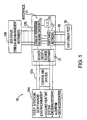
- the test station is programmed by the end user with generic tests of the operating parameters of the hardware.
- This test information is encoded and sent to the interface so that monitoring of the control lines from the test station will not reveal the true test parameters. This may include the sending of spurious signals at certain times, which the interface is programmed to ignore.
- the interface is also connected to stimulus and measurement equipment in the test station which provide test signals and measure the response of the hardware to those signals. The interface encodes the test results and sends them back to the test station for evaluation as to whether the hardware is operating properly or not.
Landscapes
- Engineering & Computer Science (AREA)
- General Engineering & Computer Science (AREA)
- Theoretical Computer Science (AREA)
- Computer Hardware Design (AREA)
- Quality & Reliability (AREA)
- Physics & Mathematics (AREA)
- General Physics & Mathematics (AREA)
- Test And Diagnosis Of Digital Computers (AREA)
- Tests Of Electronic Circuits (AREA)
- Maintenance And Management Of Digital Transmission (AREA)
- Mobile Radio Communication Systems (AREA)
Description
Claims (10)
- A system for testing a hardware unit containing sensitive information, while inhibiting access to that information, said system comprising:a test station (10) having a programmed processor, generating equipment which generates encoded test information, and measuring devices which measure the response of the unit to actual test signals, said test station containing a test program which does not indicate the sensitive information and a secured run-time program that interprets the test-program to generate encoded commands for carrying out the test; andan encapsulated interface circuit (14) which (1) receives the encoded commands and encoded test information from the test station, decodes the encoded commands, generates the actual test signals from the encoded test information, and routes the actual test signals to the unit under test, and (2) receives the response of the unit under test, encodes the response, and sends the encoded response to the test station for interpretation.
- The system of claim 1 wherein said interface circuit, comprises:an encoder/decoder circuit (11) for decoding and encoding signals from and to said test station by changing their format; anda switching network for creating paths between the generating equipment and the unit under test based on commands from said test station.
- The system of claim 2 wherein said interface further includes
a local oscillator (13) for generating a frequency signal; and
generation and mixing circuits (15) which receive the encoded test information from said generating equipment and said frequency signal and combine them to form the actual test signals based on commands from said test station. - The system of claim 1 further including a user control which inhibits control of the test station in the absence of a proper user identification code.
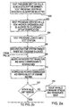
- The system of claim 1 further including an interface validation module (210) which verifies the command codes received by the interface circuit and terminates the test if an unverified signal is received.
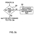
- The system of claim 1 further including a test station validation module (230) which verifies the responses received by the test station from the interface circuit and terminates the test if an unverified signal is received.
- A method for operating a system for testing a hardware unit containing sensitive information, while inhibiting access to that information, said method comprising the steps of:loading a test program, which does not indicate the sensitive information, and a secured run-time program into a programmed processor of a test station (10);executing the secured run-time program to encode the test program to generate encoded commands for carrying out the test;transmitting the encoded commands to an encapsulated interface circuit (14);providing a path from signal generating and measuring equipment in the test station to the encapsulated interface circuit;using the interface circuit to apply outputs from the signal generating equipment to the unit (16) under test according to the commands from the test station;receiving in the interface circuit responses from the unit under test; andencoding the responses and transmitting them to the test station for measurement by the measuring equipment.
- The method of claim 7 wherein the step of encoding the test program includes at least one of changing the format and specifying a particular time for transmission thereof.
- The method of claim 7 wherein the step of encoding the responses includes at least one of changing the format and specifying a particular time for transmission thereof.
- The method of claim 7 wherein the step of using the interface circuit to apply outputs from signal generating equipment to the unit under test comprises the steps of:creating a local frequency;selecting outputs of the signal generating equipment according to the commands;mixing the local frequency and selected outputs; andswitching the mixed signals so as to apply them to the unit under test.
Applications Claiming Priority (3)
| Application Number | Priority Date | Filing Date | Title |
|---|---|---|---|
| US8211398P | 1998-04-17 | 1998-04-17 | |
| US82113P | 1998-04-17 | ||
| PCT/US1999/008321 WO1999057567A2 (en) | 1998-04-17 | 1999-04-15 | Method and apparatus for protecting sensitive data during automatic testing of hardware |
Publications (2)
| Publication Number | Publication Date |
|---|---|
| EP1073906A2 EP1073906A2 (en) | 2001-02-07 |
| EP1073906B1 true EP1073906B1 (en) | 2002-07-31 |
Family
ID=22169146
Family Applications (1)
| Application Number | Title | Priority Date | Filing Date |
|---|---|---|---|
| EP99940788A Expired - Lifetime EP1073906B1 (en) | 1998-04-17 | 1999-04-15 | Method and apparatus for protecting sensitive data during automatic testing of hardware |
Country Status (9)
| Country | Link |
|---|---|
| US (1) | US6397353B1 (en) |
| EP (1) | EP1073906B1 (en) |
| JP (1) | JP2003526085A (en) |
| KR (1) | KR20010042770A (en) |
| AU (1) | AU5457299A (en) |
| DE (1) | DE69902372T2 (en) |
| IL (1) | IL139088A (en) |
| TR (1) | TR200003026T2 (en) |
| WO (1) | WO1999057567A2 (en) |
Families Citing this family (5)
| Publication number | Priority date | Publication date | Assignee | Title |
|---|---|---|---|---|
| JP4289479B2 (en) * | 2003-01-08 | 2009-07-01 | Okiセミコンダクタ株式会社 | LSI test program protection method |
| US7840945B2 (en) * | 2006-01-05 | 2010-11-23 | International Business Machines Corporation | Software resource testing |
| WO2008045117A1 (en) * | 2006-10-06 | 2008-04-17 | Nielsen Media Research, Inc. | Methods and apparatus to analyze computer software |
| WO2008084425A2 (en) * | 2007-01-11 | 2008-07-17 | Nds Limited | Processing video content |
| US8330122B2 (en) * | 2007-11-30 | 2012-12-11 | Honeywell International Inc | Authenticatable mark, systems for preparing and authenticating the mark |
Family Cites Families (4)
| Publication number | Priority date | Publication date | Assignee | Title |
|---|---|---|---|---|
| IL94115A (en) * | 1990-04-18 | 1996-06-18 | Ibm Israel | Dynamic process for the generation of biased pseudo-random test patterns for the functional verification of hardware designs |
| FR2694093B1 (en) * | 1992-07-24 | 1996-08-02 | Point Pacific | METHOD AND DEVICE FOR REMOTELY CONTROLLING THE CONFORMITY OF A PRODUCT INCLUDING AN ELECTRONIC CIRCUIT. |
| GB2278213A (en) * | 1993-05-18 | 1994-11-23 | Ibm | Test program generator. |
| US5572666A (en) * | 1995-03-28 | 1996-11-05 | Sun Microsystems, Inc. | System and method for generating pseudo-random instructions for design verification |
-
1999
- 1999-04-09 US US09/289,490 patent/US6397353B1/en not_active Expired - Lifetime
- 1999-04-15 EP EP99940788A patent/EP1073906B1/en not_active Expired - Lifetime
- 1999-04-15 JP JP2000547482A patent/JP2003526085A/en not_active Withdrawn
- 1999-04-15 AU AU54572/99A patent/AU5457299A/en not_active Abandoned
- 1999-04-15 TR TR2000/03026T patent/TR200003026T2/en unknown
- 1999-04-15 WO PCT/US1999/008321 patent/WO1999057567A2/en not_active Ceased
- 1999-04-15 DE DE69902372T patent/DE69902372T2/en not_active Expired - Lifetime
- 1999-04-15 IL IL13908899A patent/IL139088A/en not_active IP Right Cessation
- 1999-04-15 KR KR1020007011505A patent/KR20010042770A/en not_active Withdrawn
Also Published As
| Publication number | Publication date |
|---|---|
| KR20010042770A (en) | 2001-05-25 |
| EP1073906A2 (en) | 2001-02-07 |
| DE69902372T2 (en) | 2003-03-06 |
| AU5457299A (en) | 1999-11-23 |
| WO1999057567A2 (en) | 1999-11-11 |
| JP2003526085A (en) | 2003-09-02 |
| WO1999057567A3 (en) | 2000-01-27 |
| US6397353B1 (en) | 2002-05-28 |
| TR200003026T2 (en) | 2001-01-22 |
| IL139088A0 (en) | 2001-11-25 |
| IL139088A (en) | 2003-09-17 |
| DE69902372D1 (en) | 2002-09-05 |
Similar Documents
| Publication | Publication Date | Title |
|---|---|---|
| US8489888B2 (en) | Processor apparatus having a security function | |
| US20080098224A1 (en) | Processes and apparatus for establishing a secured connection with a joint test action group port | |
| KR100818620B1 (en) | Method for testing an integrated circuit including hardware and/or software parts having a confidential nature | |
| US6397353B1 (en) | Method and apparatus for protecting sensitive data during automatic testing of hardware | |
| CN118520480A (en) | Vehicle diagnosis information transmission method, device, equipment and storage medium | |
| JP5490114B2 (en) | Integrated circuit, method and electronic apparatus | |
| US8171542B2 (en) | Advanced encryption standard to provide hardware key interface | |
| CN206195821U (en) | Industry control network security detection device | |
| Carullo et al. | Security issues for internet-based calibration activities | |
| Espedahlen | Attack trees describing security in distributed internet-enabled metrology | |
| Nygård et al. | Leveraging Hardware Reverse Engineering to Improve the Cyber Security and Resilience of the Smart Grid. | |
| CN121935976A (en) | Control method, device and system for chip security access and chip | |
| CN112910886A (en) | Method and system for verifying identity of lock | |
| CN113076342A (en) | Inter-chain dynamic rule data verification method and system based on Mysql and PlatONE alliance | |
| Huang et al. | MSIPS: Multi-tiered security IPs architecture for secure SoC design | |
| CN117319639B (en) | Set top box testing method, related device, equipment and readable storage medium | |
| CN108257272A (en) | Replicate the method and system of unlocker device | |
| EP1785905A1 (en) | Advanced encyrption standard to provide hardware key interface | |
| Hawrylak et al. | Automated test system for ISO 18000-7-active RFID | |
| Wolford et al. | Software Authentication | |
| SUZUKI et al. | Technical regulation conformity evaluation system for software defined radio | |
| Crouch et al. | A role for embedded instrumentation in real-time hardware assurance and online monitoring against cybersecurity threats | |
| KR100285306B1 (en) | Voice quality test related with vocoder in cdma cellular systems | |
| Savithri et al. | CRYPTOGUARD–IoT Biometric Home Security | |
| Guidry | The Design and Overview of AcCCS: A Cyber-Physical Toolkit for Cyber-Analysis and Conformance Testing Providing Access Through CCS |
Legal Events
| Date | Code | Title | Description |
|---|---|---|---|
| PUAI | Public reference made under article 153(3) epc to a published international application that has entered the european phase |
Free format text: ORIGINAL CODE: 0009012 |
|
| 17P | Request for examination filed |
Effective date: 20001013 |
|
| AK | Designated contracting states |
Kind code of ref document: A2 Designated state(s): BE DE FR GB IT NL |
|
| GRAG | Despatch of communication of intention to grant |
Free format text: ORIGINAL CODE: EPIDOS AGRA |
|
| RIC1 | Information provided on ipc code assigned before grant |
Free format text: 7G 06F 11/273 A |
|
| 17Q | First examination report despatched |
Effective date: 20010925 |
|
| GRAG | Despatch of communication of intention to grant |
Free format text: ORIGINAL CODE: EPIDOS AGRA |
|
| GRAH | Despatch of communication of intention to grant a patent |
Free format text: ORIGINAL CODE: EPIDOS IGRA |
|
| GRAH | Despatch of communication of intention to grant a patent |
Free format text: ORIGINAL CODE: EPIDOS IGRA |
|
| GRAH | Despatch of communication of intention to grant a patent |
Free format text: ORIGINAL CODE: EPIDOS IGRA |
|
| GRAA | (expected) grant |
Free format text: ORIGINAL CODE: 0009210 |
|
| GRAH | Despatch of communication of intention to grant a patent |
Free format text: ORIGINAL CODE: EPIDOS IGRA |
|
| AK | Designated contracting states |
Kind code of ref document: B1 Designated state(s): BE DE FR GB IT NL |
|
| REG | Reference to a national code |
Ref country code: GB Ref legal event code: FG4D |
|
| REF | Corresponds to: |
Ref document number: 69902372 Country of ref document: DE Date of ref document: 20020905 |
|
| ET | Fr: translation filed | ||
| PLBE | No opposition filed within time limit |
Free format text: ORIGINAL CODE: 0009261 |
|
| STAA | Information on the status of an ep patent application or granted ep patent |
Free format text: STATUS: NO OPPOSITION FILED WITHIN TIME LIMIT |
|
| 26N | No opposition filed |
Effective date: 20030506 |
|
| PGFP | Annual fee paid to national office [announced via postgrant information from national office to epo] |
Ref country code: BE Payment date: 20080507 Year of fee payment: 10 |
|
| PGFP | Annual fee paid to national office [announced via postgrant information from national office to epo] |
Ref country code: NL Payment date: 20080325 Year of fee payment: 10 |
|
| BERE | Be: lapsed |
Owner name: *ALLIEDSIGNAL INC. Effective date: 20090430 |
|
| NLV4 | Nl: lapsed or anulled due to non-payment of the annual fee |
Effective date: 20091101 |
|
| PG25 | Lapsed in a contracting state [announced via postgrant information from national office to epo] |
Ref country code: NL Free format text: LAPSE BECAUSE OF NON-PAYMENT OF DUE FEES Effective date: 20091101 |
|
| PG25 | Lapsed in a contracting state [announced via postgrant information from national office to epo] |
Ref country code: BE Free format text: LAPSE BECAUSE OF NON-PAYMENT OF DUE FEES Effective date: 20090430 |
|
| PGFP | Annual fee paid to national office [announced via postgrant information from national office to epo] |
Ref country code: GB Payment date: 20120327 Year of fee payment: 14 |
|
| PGFP | Annual fee paid to national office [announced via postgrant information from national office to epo] |
Ref country code: DE Payment date: 20120430 Year of fee payment: 14 |
|
| PGFP | Annual fee paid to national office [announced via postgrant information from national office to epo] |
Ref country code: FR Payment date: 20120503 Year of fee payment: 14 |
|
| PGFP | Annual fee paid to national office [announced via postgrant information from national office to epo] |
Ref country code: IT Payment date: 20120419 Year of fee payment: 14 |
|
| GBPC | Gb: european patent ceased through non-payment of renewal fee |
Effective date: 20130415 |
|
| PG25 | Lapsed in a contracting state [announced via postgrant information from national office to epo] |
Ref country code: GB Free format text: LAPSE BECAUSE OF NON-PAYMENT OF DUE FEES Effective date: 20130415 Ref country code: DE Free format text: LAPSE BECAUSE OF NON-PAYMENT OF DUE FEES Effective date: 20131101 |
|
| REG | Reference to a national code |
Ref country code: FR Ref legal event code: ST Effective date: 20131231 |
|
| REG | Reference to a national code |
Ref country code: DE Ref legal event code: R119 Ref document number: 69902372 Country of ref document: DE Effective date: 20131101 |
|
| PG25 | Lapsed in a contracting state [announced via postgrant information from national office to epo] |
Ref country code: FR Free format text: LAPSE BECAUSE OF NON-PAYMENT OF DUE FEES Effective date: 20130430 Ref country code: IT Free format text: LAPSE BECAUSE OF NON-PAYMENT OF DUE FEES Effective date: 20130415 |
|
| P01 | Opt-out of the competence of the unified patent court (upc) registered |
Effective date: 20230525 |