EP1073828B1 - Containment system for containing blade burst - Google Patents
Containment system for containing blade burst Download PDFInfo
- Publication number
- EP1073828B1 EP1073828B1 EP99915416A EP99915416A EP1073828B1 EP 1073828 B1 EP1073828 B1 EP 1073828B1 EP 99915416 A EP99915416 A EP 99915416A EP 99915416 A EP99915416 A EP 99915416A EP 1073828 B1 EP1073828 B1 EP 1073828B1
- Authority
- EP
- European Patent Office
- Prior art keywords
- containment
- containment system
- ring
- circumferential
- engine
- Prior art date
- Legal status (The legal status is an assumption and is not a legal conclusion. Google has not performed a legal analysis and makes no representation as to the accuracy of the status listed.)
- Expired - Lifetime
Links
- 239000000463 material Substances 0.000 claims description 17
- 230000000295 complement effect Effects 0.000 claims description 15
- 239000012634 fragment Substances 0.000 claims description 3
- 239000002184 metal Substances 0.000 claims description 3
- 229910052751 metal Inorganic materials 0.000 claims description 3
- 239000007789 gas Substances 0.000 description 13
- 239000010410 layer Substances 0.000 description 5
- 239000000835 fiber Substances 0.000 description 4
- 239000002657 fibrous material Substances 0.000 description 3
- 238000004519 manufacturing process Methods 0.000 description 3
- 229920000271 Kevlar® Polymers 0.000 description 1
- QXZUUHYBWMWJHK-UHFFFAOYSA-N [Co].[Ni] Chemical compound [Co].[Ni] QXZUUHYBWMWJHK-UHFFFAOYSA-N 0.000 description 1
- 230000006978 adaptation Effects 0.000 description 1
- 230000015572 biosynthetic process Effects 0.000 description 1
- 239000000567 combustion gas Substances 0.000 description 1
- 238000002485 combustion reaction Methods 0.000 description 1
- 239000002131 composite material Substances 0.000 description 1
- 230000006835 compression Effects 0.000 description 1
- 238000007906 compression Methods 0.000 description 1
- 238000010276 construction Methods 0.000 description 1
- 239000012792 core layer Substances 0.000 description 1
- 239000004761 kevlar Substances 0.000 description 1
- 230000007257 malfunction Effects 0.000 description 1
- 238000000034 method Methods 0.000 description 1
- 238000012986 modification Methods 0.000 description 1
- 230000004048 modification Effects 0.000 description 1
- 230000002093 peripheral effect Effects 0.000 description 1
- 239000002356 single layer Substances 0.000 description 1
- 239000007787 solid Substances 0.000 description 1
- 230000003068 static effect Effects 0.000 description 1
- 238000004804 winding Methods 0.000 description 1
Images

Classifications
-
- F—MECHANICAL ENGINEERING; LIGHTING; HEATING; WEAPONS; BLASTING
- F01—MACHINES OR ENGINES IN GENERAL; ENGINE PLANTS IN GENERAL; STEAM ENGINES
- F01D—NON-POSITIVE DISPLACEMENT MACHINES OR ENGINES, e.g. STEAM TURBINES
- F01D21/00—Shutting-down of machines or engines, e.g. in emergency; Regulating, controlling, or safety means not otherwise provided for
- F01D21/04—Shutting-down of machines or engines, e.g. in emergency; Regulating, controlling, or safety means not otherwise provided for responsive to undesired position of rotor relative to stator or to breaking-off of a part of the rotor, e.g. indicating such position
- F01D21/045—Shutting-down of machines or engines, e.g. in emergency; Regulating, controlling, or safety means not otherwise provided for responsive to undesired position of rotor relative to stator or to breaking-off of a part of the rotor, e.g. indicating such position special arrangements in stators or in rotors dealing with breaking-off of part of rotor
-
- F—MECHANICAL ENGINEERING; LIGHTING; HEATING; WEAPONS; BLASTING
- F05—INDEXING SCHEMES RELATING TO ENGINES OR PUMPS IN VARIOUS SUBCLASSES OF CLASSES F01-F04
- F05D—INDEXING SCHEME FOR ASPECTS RELATING TO NON-POSITIVE-DISPLACEMENT MACHINES OR ENGINES, GAS-TURBINES OR JET-PROPULSION PLANTS
- F05D2220/00—Application
- F05D2220/50—Application for auxiliary power units (APU's)
-
- Y—GENERAL TAGGING OF NEW TECHNOLOGICAL DEVELOPMENTS; GENERAL TAGGING OF CROSS-SECTIONAL TECHNOLOGIES SPANNING OVER SEVERAL SECTIONS OF THE IPC; TECHNICAL SUBJECTS COVERED BY FORMER USPC CROSS-REFERENCE ART COLLECTIONS [XRACs] AND DIGESTS
- Y02—TECHNOLOGIES OR APPLICATIONS FOR MITIGATION OR ADAPTATION AGAINST CLIMATE CHANGE
- Y02T—CLIMATE CHANGE MITIGATION TECHNOLOGIES RELATED TO TRANSPORTATION
- Y02T50/00—Aeronautics or air transport
- Y02T50/60—Efficient propulsion technologies, e.g. for aircraft
Definitions
- the present invention relates to a cylindrical protection ring for use in turbine engine housings, and in particular, a rotor blade burst protection ring for use in a gas turbine compartment.
- Protection rings are generally used for externally surrounding or enclosing the rotor areas or fan areas of gas turbine engines used on aircraft.
- modern gas turbine engines can perform for thousands of hours without any significant malfunction, circumstances have arisen where the gear box controlling the drive shaft of the engine decouples from the drive shaft as a result of gear failure.
- the result of such decoupling is that the drive shaft no longer faces a resistance and begins to continuously increase rotational speed.
- the turbine blade hub can separate from the drive shaft, and be forced radially outward in to the engine housing.
- the turbine blades attached to a blade hub may be designed to sever or "burst" from the hub before the hub severs from the drive shaft.
- the containment ring comprises a rigid cylinder which is covered on its periphery with layers of fibrous material, consisting of a plurality of pieces of woven material. Further layers of the fibrous material are wrapped or wound around the core layer and then coated with an impervious material.
- the present invention provides a containment system for containing blades or fragments of blades resulting from a blade failure, comprising a first inner circumferential containment means and a second outer circumferential containment means surrounding said first inner circumferential containment means each with a complementary inner surface; and a circumferential sheet of ductile material separating the first inner circumferential containment means and said second outer circumferential containment means in closely spaced relationship; and mounting means for mounting said first and second circumferential containment means in said closely spaced relationship, wherein a first of said complementary inner surfaces includes a plurality of convex protrusions and a second of said complementary inner surfaces includes a plurality of concave recesses.
- the first inner containment ring has a plurality of ribs which are configured and arranged to intermesh with a plurality of grooves on the second outer containment ring.
- the first cylindrical inner containment ring and the second outer cylindrical containment ring are separated by a ductile sheet of metal which absorbs the kinetic energy of a blade burst in the turbine blade compartment.
- a turbine blade or blades are subjected to the high centrifugal forces which create a turbine blade burst condition, the movement of the separated turbine blade forces the inner containment ring towards the outer containment ring and absorbs the kinetic energy of the burst.
- the sheet of ductile material is bent or punctured during this process and thus further absorbs the kinetic energy of the blade burst and damps the movement of the first inner containment ring with respect to the second outer containment ring.
- the invention is addressed to a containment system comprising a first inner circumferential containment means; a second outer circumferential containment means; a set of convex protrusions on one of said first inner containment means and second outer containment means; a set of concave recesses on the other of said first inner containment means and second outer containment means; wherein said convex protrusions and concave recesses intermesh with an interference fit.
- the inner and outer containment rings are not separated by a ductile material, and the concave recesses and convex protrusions will intermesh in a tight interference fit. Since high levels of energy must be expended to force the protrusions into the recesses, the system is capable of absorbing the high levels of energy released during a blade burst.
- the use of the containment ring of the present invention also permits weight savings over the conventional prior art single layer containment rings.
- the containment ring of the present invention is simpler to manufacture than prior art containment housings utilizing complex fiber windings necessary with the use of KEVLAR, or other types of composite materials known in the art and utilized in such applications.
- the present invention is also slightly lighter in weight than the previous spirally wound containment rings, such as that disclosed in U.S. patent 5,163,809 to Akgun et al.
- Figure 1 of the present invention discloses a cross sectional view of an axial flow gas turbine engine 10.
- the engine includes a plurality of turbine blades 20 connected to respective blade hub 30.
- Each of the blades 20 is designed to include a slightly weakened portion along the length of the blade airfoil, or at the connection between the blade airfoil 20 and the blade hub (not shown). This design feature is included as a safety feature, and prevents the larger and heavier turbine blade hub from failing before the lighter and thinner blades 20.
- the blade hub 30 is in turn connected to a central engine drive shaft 40 which provides power to a reduction gear box 50.
- Forward of the turbine blades 20 are compressor and turbine stages 60, which are composed of a series of blade rows which compress air initially entering the engine duct.
- an exhaust duct 70 for exhausting the combustion gases from the combustion section of the gas turbine engine.
- Circumferentially surrounding the turbine blades 20 is a cylindrical containment ring generally indicated by the reference numeral 80.
- the cylindrical containment ring is formed from a first inner containment ring 81, which is circumferentially surrounded by a second outer containment ring 82.
- the first inner containment ring 81 is formed with a series of ribs 87 extending along an outer surface of the ring.
- the second outer containment ring 82 is formed with a complementary series of grooves 88 on the inner surface of the ring, and which are designed and arranged to interfit with the ribs 87.
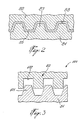
- Each of the ribs 87 and the grooves 88 may be formed with a tapered configuration, as better shown in FIG. 2.
- ribs and grooves such as generally convex protrusions and generally concave recesses are within the scope of the present of the present invention.
- formation of concave recesses on the inner containment ring and complementary protrusions on the outer containment ring are also considered to be within the scope of the present invention.
- a ductile sheet of material 83 Located between the ribs 87 of the first inner containment ring 81 and the grooves 88 of the outer containment ring 82 is a ductile sheet of material 83 preferably formed from a sheet of metal of approximately 30 to 40 mils thickness.
- the ductile sheet of material 83 is designed and configured to bend under the high loading forces created when the first inner containment ring absorbs the energy from a burst blade 20.
- the first inner containment ring is supported by a mounting means, including a first leg 84, which in cross section, has a generally U-shaped configuration.
- the second containment ring is supported by a second outer leg 86, which intersects with the first inner leg 84 to define a juncture 90.
- Extending from the juncture 90 is a third leg 85.
- the first inner containment ring 81 and the second outer containment ring 82 are supported in position by a plurality of fasteners 91 and 92.
- the juncture 90 is supported by a first fastener 91, and the peripheral end of the support leg 85 is supported by a second fastener 92.
- the first fastener 91 and the second fastener 92 are fixed in a static position to the outer engine housing (not shown). Since the first inner ring 81 is designed to deform with respect to the second outer ring 82, the inner ring 81 and the inner leg 84, are thus formed from a material which is generally more ductile than the material forming the outer containment ring 82 and the legs 85 and 86.
- Figure 3 illustrates an alternate embodiment of the present invention for a containment ring structure shown generally at 100.
- the inner containment ring 81 includes a plurality of convex protrusions 101 which interfit with a plurality of concave recesses 102 on the outer containment ring 82.
- the protrusions and recesses may be formed from a variety of shapes, and may have matching, complementary shapes, or unmatched non-complementary shapes. In the embodiment shown in Fig. 3, the shapes are non-complementary, with the protrusions 101 being generally conical in shape, and the recesses 102 being generally rectangular in shape. Unlike the previous embodiment, this embodiment does not utilize a thin layer of ductile material between the inner and outer containment rings 81, 82.
- this embodiment is designed to create a tight interference fit between the protrusions 101 and the recesses 102, when the inner containment ring is deformed outwardly towards the outer ring 82 by a blade burst. Because a tight interference fit requires that a large amount of energy be expended to force the protrusions into the recesses, this design permits the containment ring system to absorb the high levels of kinetic energy released when a failed blade strikes the inner containment ring.
- a gas turbine engine is designed to include turbine blades which fail before any mechanical failure of the blade hub. This can be accomplished by designing each blade to include a slight nick or weakness along its length.
- the turbine blades from the blade section 20 are expelled radially outwardly against the inner surface of the first inner ring 81.
- the kinetic energy of the blade translates into a deformation of the inner ring 81 relative to the outer ring 82.
- the ductile sheet of material 83 absorbs this transfer of energy and is either bent or punctured by the deformation of the inner ring with respect to the outer ring, as shown in FIG. 2.
- the inner containment ring transfers the kinetic energy of the blade burst to the interference fitted protrusions 101 and recesses 102 on the respective inner and outer containment rings 81, 82. Since a high level of energy must be expended to move the protrusions relative to the recesses in an interference fit, the energy of the blade burst is absorbed by the movement of the protrusions 101 into the respective recesses 102.
- the outer ring 82 is also capable of absorbing the transfer of energy from a blade fracture or blade burst
- the outer ring 82 is formed from a less ductile material than the material used to form the inner containment ring 81.
- the outer ring 82 will thus remain substantially in place while permitting the inner ring 81 to absorb most of the energy released during a blade burst condition.
- Such a design permits the engine to remain intact during a failure of one or more the blades 20, while simultaneously absorbing the sudden transfer of energy from loose or broken blades against the inner wall of the engine housing.
- the containment rings of the present invention are also relatively easy to manufacture, as they are formed from only three fundamental parts, namely, the inner containment ring 81, the outer containment ring 82 and the ductile sheet of material 83 sandwiched between the inner and outer rings.
- the containment shroud system may also be applied to other engine sections as well, including, but not limited to the air compression section, or any other section of a gas turbine engine which contains a set of rotating rotor blades.
- the present invention is also not limited to applications in gas turbine engines, but may be utilized in any type of system which incorporates a set of rotating blades, or other types of systems known to one of ordinary skill in the art where it is desirable to contain a blade failure.
- the containment system may be formed as a multiple layer system.
Landscapes
- Engineering & Computer Science (AREA)
- Mechanical Engineering (AREA)
- General Engineering & Computer Science (AREA)
- Turbine Rotor Nozzle Sealing (AREA)
- Structures Of Non-Positive Displacement Pumps (AREA)
- Control Of Turbines (AREA)
Description
In this aspect of the invention, the inner and outer containment rings are not separated by a ductile material, and the concave recesses and convex protrusions will intermesh in a tight interference fit. Since high levels of energy must be expended to force the protrusions into the recesses, the system is capable of absorbing the high levels of energy released during a blade burst.
Claims (24)
- A containment system for containing blades (20) or fragments of blades resulting from a blade failure within an engine housing, comprising:a first inner circumferential containment means (81);a second outer circumferential containment means (82) surrounding said first inner circum-ferential containment means (81);a circumferential sheet (83) of ductile material between said first inner circumferential containment means (81) and said second outer circumferential containment means (82); andmounting means (84, 85, 86) for mounting said first and second circumferential containment means (81, 82) in a closely spaced relationship each with a respective complementary inner surface, characterized in that a first of said complementary inner surfaces includes a plurality of convex protrusions (87), and a second of said complementary inner surfaces includes a plurality of concave recesses (88).
- The containment system as claimed in claim 1, wherein said convex protrusions (87) are ribs and said concave recesses (88) are grooves.
- The containment system of claim 2, ,wherein said ribs (87) and said grooves (88) extend circumferentially of said complementary inner surfaces.
- The containment system as claimed in claim 3, wherein said ribs (87) and grooves (88) are tapered.
- The containment system as claimed in claim 1, wherein said ductile sheet (83) is spaced between said first complementary inner surface and said second complementary inner surface.
- The containment system as claimed in claim 1, wherein said ductile sheet (83) is a relatively thin sheet of metal.
- The containment system as claimed in claim 6, wherein said ductile sheet (83) has a thickness of about 30 mils.
- The containment system as claimed in claim 6, wherein said ductile sheet (83) has a thickness of about 40 mils.
- The containment system as claimed in claim 1, wherein said first circumferential containment means (81) is formed from a material with a higher ductility than said second containment means (82).
- The containment system as claimed in claim 1, wherein said mounting means comprises a plurality of legs (84, 85, 86).
- The containment system as claimed in claim 8, wherein said first and second circumferential containment means (81, 82) are integrally mounted to said legs (84, 85, 86).
- The containment system as claimed in claim 8, wherein said legs (84, 85, 86) are, fixedly mounted to a housing, radially outward of said blades (20).
- The containment system as claimed in claim 10, wherein said legs (84, 85, 86) are fixedly mounted to said housing by fasteners (91, 92).
- The containment system as claimed in claim 1 in combination with a turbine engine system, including a compressor section, a turbine section and an exhaust section, further characterized in that said first and second containment means are annular rings (81, 82) that circumferentially surround one of said compressor and turbine sections (60).
- The containment system as claimed in claim 14, wherein said first and second containment means are annular rings (81, 82) concentrically aligned with one of said compressor and turbine sections (60).
- The containment system of claim 14, wherein said turbine engine is a gas turbine engine.
- The containment system of claim 14, wherein said turbine engine is a turboprop engine.
- The containment system of claim 14, wherein said turbine engine forms part of an auxiliary power unit.
- The containment system of claim 14, wherein said turbine engine is a jet engine.
- The containment system of claim 1, wherein said first inner circumferential containment means (81) and said second outer circumferential containment means (82) are rings.
- A containment system for containing blades or fragments of blades resulting from a blade failure within an engine housing, comprising:characterized in that there is a set of convex protrusions (87) on one of said first inner circumferential containment ring (81) and second outer circumferential containment ring (82);a first inner circumferential containment ring (81);a second outer circumferential containment ring (82) surrounding said first inner circum-ferential containment ring (81);
a set of concave recesses (88) on the other of said first inner circumferential containment ring (81) and second outer circumferential containment ring (82);
wherein said convex protrusions and concave recesses intermesh with an interference fit. - The containment system of claim 21, wherein said convex protrusions (87) have a substantially different cross-sectional shape than a cross-sectional shape of the concave recesses (88) .
- The containment system of claim 22, wherein one of said cross-sectional shapes is substantially trapezoidal and another of said cross-sectional shapes is rectangular.
- The containment system of claim 21, wherein said convex protrusions have a cross-sectional shape which is complementary to a cross-sectional shape of said convex protrusions.
Applications Claiming Priority (3)
| Application Number | Priority Date | Filing Date | Title |
|---|---|---|---|
| US09/062,618 US6059523A (en) | 1998-04-20 | 1998-04-20 | Containment system for containing blade burst |
| US62618 | 1998-04-20 | ||
| PCT/CA1999/000340 WO1999054598A1 (en) | 1998-04-20 | 1999-04-19 | Containment system for containing blade burst |
Publications (2)
| Publication Number | Publication Date |
|---|---|
| EP1073828A1 EP1073828A1 (en) | 2001-02-07 |
| EP1073828B1 true EP1073828B1 (en) | 2004-06-30 |
Family
ID=22043680
Family Applications (1)
| Application Number | Title | Priority Date | Filing Date |
|---|---|---|---|
| EP99915416A Expired - Lifetime EP1073828B1 (en) | 1998-04-20 | 1999-04-19 | Containment system for containing blade burst |
Country Status (6)
| Country | Link |
|---|---|
| US (1) | US6059523A (en) |
| EP (1) | EP1073828B1 (en) |
| JP (1) | JP2002512335A (en) |
| CA (1) | CA2329715C (en) |
| DE (1) | DE69918427T2 (en) |
| WO (1) | WO1999054598A1 (en) |
Cited By (5)
| Publication number | Priority date | Publication date | Assignee | Title |
|---|---|---|---|---|
| US10215050B2 (en) | 2013-09-03 | 2019-02-26 | MTU Aero Engines AG | Apparatus for energy absorption, a turbo-machine and a method for energy absorption |
| US11015482B2 (en) | 2018-11-27 | 2021-05-25 | Honeywell International Inc. | Containment system for gas turbine engine |
| EP4592503A1 (en) * | 2024-01-29 | 2025-07-30 | Pratt & Whitney Canada Corp. | Containment ring for gas turbine engine |
| EP4592505A1 (en) * | 2024-01-29 | 2025-07-30 | Pratt & Whitney Canada Corp. | Containment ring for gas turbine engine |
| US12404780B2 (en) | 2024-01-29 | 2025-09-02 | Pratt & Whitney Canada Corp. | Containment ring for gas turbine engine |
Families Citing this family (24)
| Publication number | Priority date | Publication date | Assignee | Title |
|---|---|---|---|---|
| TW576886B (en) * | 2001-05-04 | 2004-02-21 | Abb Turbo Systems Ag | Turbocharger having a radial-flow compressor and burst-protection arrangement for a radial-flow compressor of a turbocharger |
| AU2003238992A1 (en) * | 2002-06-05 | 2003-12-22 | Volvo Aero Corporation | A turbine and a component |
| US7165937B2 (en) * | 2004-12-06 | 2007-01-23 | General Electric Company | Methods and apparatus for maintaining rotor assembly tip clearances |
| GB0501284D0 (en) * | 2005-01-21 | 2005-03-02 | Rolls Royce Plc | Aerofoil containment structure |
| EP1969222B1 (en) * | 2005-12-12 | 2012-11-21 | United Technologies Corporation | Bearing-like structure to control deflections of a rotating component |
| DE102007042767A1 (en) * | 2007-09-07 | 2009-03-12 | Mtu Aero Engines Gmbh | Multilayer shielding ring for a propulsion system |
| GB2459646B (en) * | 2008-04-28 | 2011-03-30 | Rolls Royce Plc | A fan assembly |
| US8511971B2 (en) | 2010-07-23 | 2013-08-20 | Hamilton Sundstrand Corporation | One-piece compressor and turbine containment system |
| US9546563B2 (en) | 2012-04-05 | 2017-01-17 | General Electric Company | Axial turbine with containment shroud |
| FR3004215B1 (en) * | 2013-04-05 | 2018-04-20 | Airbus Operations | PROTECTIVE SCREEN FOR TURBOMACHINE HOUSING |
| DE102013210602A1 (en) * | 2013-06-07 | 2014-12-11 | MTU Aero Engines AG | Turbine housing with reinforcing elements in the containment area |
| WO2015094422A1 (en) * | 2013-12-19 | 2015-06-25 | United Technologies Corpoaration | Energy dissipating core case containment section for a gas turbine engine |
| EP3090148B1 (en) * | 2013-12-19 | 2021-05-19 | Raytheon Technologies Corporation | Gas turbine engine having energy dissipating gap and containment layer |
| GB2524320B (en) * | 2014-03-21 | 2016-05-04 | Rolls Royce Plc | Gas turbine engine |
| GB2539217B (en) | 2015-06-09 | 2020-02-12 | Rolls Royce Plc | Fan casing assembly |
| US10550718B2 (en) | 2017-03-31 | 2020-02-04 | The Boeing Company | Gas turbine engine fan blade containment systems |
| US10487684B2 (en) | 2017-03-31 | 2019-11-26 | The Boeing Company | Gas turbine engine fan blade containment systems |
| US10830050B2 (en) | 2019-01-31 | 2020-11-10 | General Electric Company | Unitary body turbine shrouds including structural breakdown and collapsible features |
| US10822986B2 (en) | 2019-01-31 | 2020-11-03 | General Electric Company | Unitary body turbine shrouds including internal cooling passages |
| USD1070922S1 (en) | 2019-01-31 | 2025-04-15 | Ge Infrastructure Technology Llc | Turbine shroud |
| US10927693B2 (en) | 2019-01-31 | 2021-02-23 | General Electric Company | Unitary body turbine shroud for turbine systems |
| EP3885537A1 (en) * | 2020-03-26 | 2021-09-29 | Unison Industries LLC | Air turbine starter containment system and method of forming such a system |
| DE102020204563A1 (en) | 2020-04-08 | 2021-10-14 | Rolls-Royce Deutschland Ltd & Co Kg | Planetary gear and gas turbine engine with planetary gear |
| CN114060305B (en) * | 2020-07-29 | 2024-07-12 | 中国航发商用航空发动机有限责任公司 | Fan containing casing and preparation method thereof |
Family Cites Families (25)
| Publication number | Priority date | Publication date | Assignee | Title |
|---|---|---|---|---|
| US1698514A (en) * | 1927-05-20 | 1929-01-08 | Westinghouse Electric & Mfg Co | Restraining guard for rotors |
| US2372723A (en) * | 1941-11-07 | 1945-04-03 | Smith Corp A O | Method of improving the stress distribution in multilayer high pressure cylinders |
| US3203180A (en) * | 1960-03-16 | 1965-08-31 | Nathan C Price | Turbo-jet powerplant |
| GB1245415A (en) * | 1968-09-13 | 1971-09-08 | Rolls Royce | Improvements in or relating to fluid flow machines |
| US3602602A (en) * | 1969-05-19 | 1971-08-31 | Avco Corp | Burst containment means |
| US3887976A (en) * | 1971-02-03 | 1975-06-10 | J Rodger Sheilds | Stator blade assembly for turbo machines |
| GB1466385A (en) * | 1974-11-21 | 1977-03-09 | Rolls Royce | Containment shields for gas turbine engines |
| US4149824A (en) * | 1976-12-23 | 1979-04-17 | General Electric Company | Blade containment device |
| GB2037900B (en) * | 1978-12-21 | 1982-09-22 | Rolls Royce | Gas turbine casing |
| FR2467977A1 (en) * | 1979-10-19 | 1981-04-30 | Snecma | SAFETY DEVICE IN THE EVENT OF TURBOMACHINE ROTATING ELEMENT BREAK |
| FR2467978A1 (en) * | 1979-10-23 | 1981-04-30 | Snecma | RETENTION DEVICE FOR A COMPRESSOR CASE OF A TURBOMACHINE |
| US4397608A (en) * | 1980-05-01 | 1983-08-09 | Automation Industries, Inc. | Energy-absorbing turbine missile shield |
| US4418560A (en) * | 1981-05-11 | 1983-12-06 | Hahn & Clay | Shell layer wrapping machine and method of positioning vessel sections of a multi-layer vessel |
| US4417848A (en) * | 1982-02-01 | 1983-11-29 | United Technologies Corporation | Containment shell for a fan section of a gas turbine engine |
| US4534698A (en) * | 1983-04-25 | 1985-08-13 | General Electric Company | Blade containment structure |
| US4547122A (en) * | 1983-10-14 | 1985-10-15 | Aeronautical Research Associates Of Princeton, Inc. | Method of containing fractured turbine blade fragments |
| GB2159886B (en) * | 1984-06-07 | 1988-01-27 | Rolls Royce | Fan duct casing |
| US4639188A (en) * | 1984-12-04 | 1987-01-27 | Sundstrand Corporation | Turbine wheel containment |
| EP0286815B1 (en) * | 1987-04-15 | 1991-05-29 | Mtu Motoren- Und Turbinen-Union MàNchen Gmbh | Containment ring for turbo machine casings |
| DE3814954A1 (en) * | 1988-05-03 | 1989-11-16 | Mtu Muenchen Gmbh | RUBBER PROTECTION RING FOR AN ENGINE HOUSING |
| US5434698A (en) * | 1989-11-13 | 1995-07-18 | Dai Nippon Printing Co., Ltd. | Potential sensor employing electrooptic crystal and potential measuring method |
| DE4329014C1 (en) * | 1993-08-28 | 1995-01-05 | Mtu Muenchen Gmbh | Rotor housing, especially housing for turbine engines |
| US5486086A (en) * | 1994-01-04 | 1996-01-23 | General Electric Company | Blade containment system |
| US5509781A (en) * | 1994-02-09 | 1996-04-23 | United Technologies Corporation | Compressor blade containment with composite stator vanes |
| US5431532A (en) * | 1994-05-20 | 1995-07-11 | General Electric Company | Blade containment system |
-
1998
- 1998-04-20 US US09/062,618 patent/US6059523A/en not_active Expired - Lifetime
-
1999
- 1999-04-19 DE DE1999618427 patent/DE69918427T2/en not_active Expired - Fee Related
- 1999-04-19 WO PCT/CA1999/000340 patent/WO1999054598A1/en not_active Ceased
- 1999-04-19 CA CA002329715A patent/CA2329715C/en not_active Expired - Lifetime
- 1999-04-19 EP EP99915416A patent/EP1073828B1/en not_active Expired - Lifetime
- 1999-04-19 JP JP2000544914A patent/JP2002512335A/en active Pending
Cited By (7)
| Publication number | Priority date | Publication date | Assignee | Title |
|---|---|---|---|---|
| US10215050B2 (en) | 2013-09-03 | 2019-02-26 | MTU Aero Engines AG | Apparatus for energy absorption, a turbo-machine and a method for energy absorption |
| US11015482B2 (en) | 2018-11-27 | 2021-05-25 | Honeywell International Inc. | Containment system for gas turbine engine |
| US11698001B2 (en) | 2018-11-27 | 2023-07-11 | Honeywell International Inc. | Containment system for gas turbine engine |
| EP4592503A1 (en) * | 2024-01-29 | 2025-07-30 | Pratt & Whitney Canada Corp. | Containment ring for gas turbine engine |
| EP4592505A1 (en) * | 2024-01-29 | 2025-07-30 | Pratt & Whitney Canada Corp. | Containment ring for gas turbine engine |
| US12398661B2 (en) | 2024-01-29 | 2025-08-26 | Pratt & Whitney Canada Corp. | Containment ring for gas turbine engine |
| US12404780B2 (en) | 2024-01-29 | 2025-09-02 | Pratt & Whitney Canada Corp. | Containment ring for gas turbine engine |
Also Published As
| Publication number | Publication date |
|---|---|
| DE69918427D1 (en) | 2004-08-05 |
| JP2002512335A (en) | 2002-04-23 |
| US6059523A (en) | 2000-05-09 |
| DE69918427T2 (en) | 2004-11-18 |
| EP1073828A1 (en) | 2001-02-07 |
| WO1999054598A1 (en) | 1999-10-28 |
| CA2329715C (en) | 2008-04-01 |
| CA2329715A1 (en) | 1999-10-28 |
Similar Documents
| Publication | Publication Date | Title |
|---|---|---|
| US6059523A (en) | Containment system for containing blade burst | |
| US6364603B1 (en) | Fan case for turbofan engine having a fan decoupler | |
| EP1199441B1 (en) | Frangible coupling ring for a fan rotor | |
| US5486086A (en) | Blade containment system | |
| EP1245791B1 (en) | A gas turbine engine blade containment assembly | |
| EP0834003B1 (en) | Fan blade containment assembly | |
| US7766603B2 (en) | Rotor blade containment assembly for a gas turbine engine | |
| US6394746B1 (en) | Gas turbine engine blade containment assembly | |
| EP0965731B1 (en) | A gas turbine containment casing | |
| US5823739A (en) | Containment case for a turbine engine | |
| US6638008B2 (en) | Gas turbine engine blade containment assembly | |
| US6739830B2 (en) | Gas turbine engine blade containment assembly | |
| CA2926867C (en) | Steel soft wall fan case | |
| US20030156940A1 (en) | Fan casing acoustic treatment | |
| JP2000179358A (en) | Gearbox locator | |
| US6497550B2 (en) | Gas turbine engine blade containment assembly | |
| US7806364B1 (en) | Containment system for a gas turbine engine | |
| CN115217629A (en) | Lightweight fan housing construction for energy absorption | |
| EP0795682B1 (en) | Blade containment system for a turbofan engine | |
| EP0922837B1 (en) | Fan case liner | |
| US12270345B2 (en) | Containment assembly for an aircraft engine |
Legal Events
| Date | Code | Title | Description |
|---|---|---|---|
| PUAI | Public reference made under article 153(3) epc to a published international application that has entered the european phase |
Free format text: ORIGINAL CODE: 0009012 |
|
| 17P | Request for examination filed |
Effective date: 20001018 |
|
| AK | Designated contracting states |
Kind code of ref document: A1 Designated state(s): DE FR GB IT SE |
|
| GRAH | Despatch of communication of intention to grant a patent |
Free format text: ORIGINAL CODE: EPIDOS IGRA |
|
| GRAS | Grant fee paid |
Free format text: ORIGINAL CODE: EPIDOSNIGR3 |
|
| GRAA | (expected) grant |
Free format text: ORIGINAL CODE: 0009210 |
|
| AK | Designated contracting states |
Kind code of ref document: B1 Designated state(s): DE FR GB IT SE |
|
| PG25 | Lapsed in a contracting state [announced via postgrant information from national office to epo] |
Ref country code: IT Free format text: LAPSE BECAUSE OF FAILURE TO SUBMIT A TRANSLATION OF THE DESCRIPTION OR TO PAY THE FEE WITHIN THE PRESCRIBED TIME-LIMIT;WARNING: LAPSES OF ITALIAN PATENTS WITH EFFECTIVE DATE BEFORE 2007 MAY HAVE OCCURRED AT ANY TIME BEFORE 2007. THE CORRECT EFFECTIVE DATE MAY BE DIFFERENT FROM THE ONE RECORDED. Effective date: 20040630 |
|
| REG | Reference to a national code |
Ref country code: GB Ref legal event code: FG4D |
|
| REF | Corresponds to: |
Ref document number: 69918427 Country of ref document: DE Date of ref document: 20040805 Kind code of ref document: P |
|
| PG25 | Lapsed in a contracting state [announced via postgrant information from national office to epo] |
Ref country code: SE Free format text: LAPSE BECAUSE OF FAILURE TO SUBMIT A TRANSLATION OF THE DESCRIPTION OR TO PAY THE FEE WITHIN THE PRESCRIBED TIME-LIMIT Effective date: 20040930 |
|
| ET | Fr: translation filed | ||
| PLBE | No opposition filed within time limit |
Free format text: ORIGINAL CODE: 0009261 |
|
| STAA | Information on the status of an ep patent application or granted ep patent |
Free format text: STATUS: NO OPPOSITION FILED WITHIN TIME LIMIT |
|
| 26N | No opposition filed |
Effective date: 20050331 |
|
| PGFP | Annual fee paid to national office [announced via postgrant information from national office to epo] |
Ref country code: GB Payment date: 20080317 Year of fee payment: 10 |
|
| PGFP | Annual fee paid to national office [announced via postgrant information from national office to epo] |
Ref country code: DE Payment date: 20080430 Year of fee payment: 10 |
|
| PGFP | Annual fee paid to national office [announced via postgrant information from national office to epo] |
Ref country code: FR Payment date: 20080403 Year of fee payment: 10 |
|
| GBPC | Gb: european patent ceased through non-payment of renewal fee |
Effective date: 20090419 |
|
| REG | Reference to a national code |
Ref country code: FR Ref legal event code: ST Effective date: 20091231 |
|
| PG25 | Lapsed in a contracting state [announced via postgrant information from national office to epo] |
Ref country code: DE Free format text: LAPSE BECAUSE OF NON-PAYMENT OF DUE FEES Effective date: 20091103 |
|
| PG25 | Lapsed in a contracting state [announced via postgrant information from national office to epo] |
Ref country code: GB Free format text: LAPSE BECAUSE OF NON-PAYMENT OF DUE FEES Effective date: 20090419 Ref country code: FR Free format text: LAPSE BECAUSE OF NON-PAYMENT OF DUE FEES Effective date: 20091222 |