BACKGROUND OF THE INVENTION
The present invention relates generally to a method of compressing or
coding digital video with bits and, specifically, to an effective method for estimating and
encoding motion vectors in motion-compensated video coding.
In classical motion estimation the current frame to be encoded is
decomposed into image blocks of the same size, typically blocks of 16x16 pixels, called
"macroblocks." For each current macroblock, the encoder searches for the block in a
previously encoded frame (the "reference frame") that best matches the current
macroblock. The coordinate shift between a current macroblock and its best match in the
reference frame is represented by a two-dimensional vector (the "motion vector") of the
macroblock. Each component of the motion vector is measured in pixel units.
For example, if the best match for a current macroblock happens to be at
the same location, as is the typical case in stationary background, the motion vector for
the current macroblock is (0,0). If the best match is found two pixels to the right and
three pixels up from the coordinates of the current macroblock, the motion vector is (2,3).
Such motion vectors are said to have integer pixel (or "integer-pel" or "full-pel")
accuracy, since their horizontal X and vertical Y components are integer pixel values. In
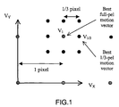
FIG. 1, the vector V1 =(1,1) represents the full-pel motion vector for a given current
macroblock.
Moving objects in a video scene do not move in integer pixel increments
from frame to frame. True motion can take any real value along the X and Y directions.
Consequently, a better match for a current macroblock can often be found by
interpolating the previous frame by a factor NxN and then searching for the best match in
the interpolated frame. The motion vectors can then take values in increments of 1/N
pixel along X and Y and are said to have 1/N pixel (or "1/N-pel") accuracy.
In "Response to Call for Proposals for H.26L," ITU-Telecommunications
Standardization Sector, Q.15/SG16, doc. Q15-F-11, Seoul, Nov. 98, and "Enhancement
of the Telenor proposal for H.26L," ITU-Telecommunications Standardization Sector,
Q.15/SG16, doc. Q15-G-25, Monterey, Feb. 99, Gisle Bjontegaard proposed using 1/3-pel
accurate motion vectors and cubic-like interpolation for the H26L video coding
standard (the "Telenor encoder"). To do this, the Telenor encoder interpolates or "up-samples"
the reference frame by 3x3 using a cubic-like interpolation filter. This
interpolated version requires nine times more memory than the reference frame. At a
given macroblock, the Telenor encoder estimates the best motion vector in two steps: the
encoder first searches for the best integer-pel vector and then the Telenor encoder
searches for the best 1/3-pixel accurate vector V1/3 near V1. Using FIG. 1 as an example,
a total of eight blocks (of 16x16 pixels) in the 3x3 interpolated reference frame are
checked to find the best match which, as shown is the block associated to the motion
vector V1/3 = (VX, VY) = (1+1/3,1). The Telenor encoder has several problems. First, it
uses a sub-optimal fast-search strategy and a complex cubic filter (at all stages) to
compute the 1/3-pel accurate motion vectors. As a result, the computed motion vectors
are not optimal and the memory and computation requirements are very expensive.
Further, the Telenor encoder uses an accuracy of the effective rate-distortion criteria that
is fixed at 1/3-pixel and, therefore, does not adapt to select better motion accuracies.
Similarly, the Telenor encoder variable-length code ("VLC") table has an accuracy fixed
at 1/3-pixel and, therefore, is not adapted and interpreted differently for different
accuracies.
Most known video compression methods estimate and encode motion
vectors with 1/2-pixel accuracy, because early studies suggested that higher or adaptive
motion accuracies would increase computational complexity without providing additional
compression gains. These early studies, however, did not estimate the motion vectors
using optimized rate-distortion criteria, did not exploit the convexity properties of such
criteria to reduce computational complexity, and did not use effective strategies to encode
the motion vectors and their accuracies.
One such early study was Bernd Girod's "Motion-Compensating
Prediction with Fractional-Pel Accuracy," IEEE Transactions on Communications,
Vol. 41, No. 4, pp. 604-612, April 1993 (the "Girod work"). The Girod work is the first
fundamental analysis on the benefits of using sub-pixel motion accuracy for video
coding. Girod used a simple, hierarchical strategy to search for the best motion vector in
sub-pixel space. He also used simple mean absolute difference ("MAD") criteria to select
the best motion vector for a given accuracy. The best accuracy was selected using a
formula that is not useful in practice since it is based on idealized assumptions, is very
complex, and restricts all motion vectors to have the same accuracy within a frame.
Finally, Girod focused only on prediction error energy and did not address how to use
bits to encode the motion vectors.
Another early study was Smita Gupta's and Allen Gersho's "On Fractional
Pixel Motion Estimation," Proc. SPIE VCIP, Vol. 2094, pp. 408-419, Cambridge,
November 1993 (the "Gupta work"). The Gupta work presented a method for computing,
selecting, and encoding motion vectors with sub-pixel accuracy for video compression.
The Gupta work disclosed a formula based on mean squared error ("MSE") and bilinear
interpolation, used this formula to find an ideal motion vector, and then quantized such
vector to the desired motion accuracy. The best motion vector for a given accuracy was
found using the sub-optimal MSE criteria and the best accuracy was selected using the
largest decrease in difference energy per distortion bit, which is a greedy (sub-optimal)
criteria. A given motion vector was coded by first encoding that vector with 1/2-pel
accuracy and then encoding the higher accuracy with refinement bits. Course-to-fine
coding tends to require significant bit overhead.
In "On the Optimal Motion Vector Accuracy for Block-Based Motion-Compensated
Video Coders," Proc. IST/SPIE Digital Video Compression: Algorithms
and Technologies, pp. 302-314, San Jose, February 1996 (the "Ribas work"), Jordi Ribas-Corbera
and David L. Neuhoff, modeled the effect of motion accuracy on bit rate and
proposed several methods to estimate the optimal accuracies that minimize bit rate. The
Ribas work set forth a full-search approach for computing motion vectors for a given
accuracy and considered only bilinear interpolation. The best motion vector was found
by minimizing MSE and the best accuracy was selected using some formulas derived
from a rate-distortion optimization. The motion vectors and accuracies were encoded
with frame-adaptive entropy coders, which are complex to implement in real-time
applications.
In "Proposal for a new core experiment on prediction enhancement at
higher bitrates," ISO/IEC JTC1/SC29/WG11 Coding of Moving Pictures and Audio,
MPEG 97/1827, Sevilla, Feb. 1997 and "Performance Evaluation of a Reduced
Complexity Implementation for Quarter Pel Motion Compensation," ISO/IEC
JTC1/SC29/WG11 Coding of Moving Pictures and Audio, MPEG 97/3146, San Jose,
Jan. 1998, Ulrich Benzler proposed using 1/4-pel accurate motion vectors for the video
sequence and more advanced interpolation filters for the MPEG4 video coding standard.
Benzler, however, used the Girod's fast-search technique to find the 1/4-pel motion
vectors. Benzler did consider different interpolation filters, but proposed a complex filter
at the first stage and a simpler filter at the second stage and interpolated one macroblock
at a time. This approach does not require much cache memory, but it is computationally
expensive because of its complexity arid because all motion vectors are computed with
1/4-pel accuracy for all the possible modes in a macroblock (e.g., 16x16, four-8x8,
sixteen-4x4, etc.) and then the best mode is determined. Benzler used the MAD criteria
to find the best motion vector which was fixed to 1/4-pel accuracy for the whole
sequence, and hence he did not address how to select the best motion accuracy. Finally,
Benzler encoded the motion vectors with a variable-length code ("VLC") table that could
be used for encoding 1/2 and 1/4 pixel accurate vectors.
The references discussed above do not estimate the motion vectors using
optimized rate-distortion criteria and do not exploit the convexity properties of such
criteria to reduce computational complexity. Further, these references do not use
effective strategies to encode motion vectors and their accuracies.
BRIEF SUMMARY OF THE INVENTION
One preferred embodiment of the present invention addresses the
problems of the prior art by computing motion vectors of high pixel accuracy (also
denoted as "fractional" or "sub-pixel" accuracy) with a minor increase in computation.
Experiments have demonstrated that, by using the search strategy of the
present invention, a video encoder can achieve significant compression gains (e.g., up to
thirty percent in bit rate savings over the classical choices of motion accuracy) using
similar levels of computation. Since the motion accuracies are adaptively computed and
selected, the present invention may be described as adaptive motion accuracy ("AMA").
One preferred embodiment of the present invention uses fast-search
strategies in sub-pixel space that smartly searches for the best motion vectors. This
technique estimates motion vectors in motion-compensated video coding by finding a
best motion vector for a macroblock. The first step is searching a first set of motion
vector candidates in a grid of sub-pixel resolution of a predetermined square radius
centered on V1 to find a best motion vector V2. Next, a second set of motion vector
candidates in a grid of sub-pixel resolution of a predetermined square radius centered on
V2 is searched to find a best motion vector V3. Then, a third set of motion vector
candidates in a grid of sub-pixel resolution of a predetermined square radius centered on
V3 is searched to find the best motion vector of the macroblock.
In an alternate preferred embodiment the present invention a technique for
estimating high-accurate motion vectors may use different interpolation filters at different
stages in order to reduce computational complexity.
Another alternate preferred embodiment of the present invention selects
the best vectors and accuracies in a rate-distortion ("RD") sense. This embodiment uses
rate-distortion criteria that adapts according to the different motion accuracies to
determine both the best motion vectors and the best motion accuracies.
Still further, another alternate preferred embodiment of the present
invention encodes the motion vector and accuracies with an effective VLC approach.
This technique uses a VLC table that is interpreted differently at different coding units,
according to the associated motion vector accuracy.
The foregoing and other objectives, features, and advantages of the
invention will be more readily understood upon consideration of the following detailed
description of the invention, taken in conjunction with the accompanying drawings.
BRIEF DESCRIPTION OF THE SEVERAL VIEWS OF THE DRAWING
FIG. 1 is a diagram of an exemplary full-pel and 1/3-pel locations in
velocity space.
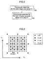
FIG. 2 is a flowchart illustrating a prior art method for estimating the best
motion vector.
FIG. 3 is a diagram of an exemplary location of motion vector candidates
for full-search in sub-pixel velocity space.
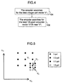
FIG. 4 is a flowchart illustrating a full-search preferred embodiment of the
method for estimating the best motion vector of the present invention.
FIG. 5 is a diagram of an exemplary location of motion vector candidates
for fast-search in sub-pixel velocity space.
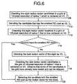
FIG. 6 is a flowchart illustrating a fast-search preferred embodiment of the
method for estimating the best motion vector of the present invention.
FIG. 7 is a detail flowchart illustrating an alternate preferred embodiment
of step 114 of FIG. 6.
FIG. 8 is a graphical representation of experimental performance results of
the Telenor encoder with and without AMA in the "Container" video sequence, with
QCIF resolution, and at the frame rate of 10 frames per second.
FIG. 9 is a graphical representation of experimental performance results of
the Telenor encoder with and without AMA in the "News" video sequence, with QCIF
resolution, and at the frame rate of 10 frames per second.
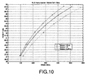
FIG. 10 is a graphical representation of experimental performance results
of the Telenor encoder with and without AMA in the "Mobile" video sequence, with
QCIF resolution, and at the frame rate of 10 frames per second.
FIG. 11 is a graphical representation of experimental performance results
of the Telenor encoder with and without AMA in the "Garden" video sequence, with SIF
resolution, and at the frame rate of 15 frames per second.
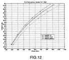
FIG. 12 is a graphical representation of experimental performance results
of the Telenor encoder with and without AMA in the "Garden" video sequence, with
QCIF resolution, and at the frame rate of 15 frames per second.
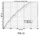
FIG. 13 is a graphical representation of experimental performance results
of the Telenor encoder with and without AMA in the "Tempete" video sequence, with
SIF resolution, and at the frame rate of 15 frames per second.
FIG. 14 is a graphical representation of experimental performance results
of the Telenor encoder with and without AMA in the "Tempete" video sequence, with
QCIF resolution, and at the frame rate of 15 frames per second.
FIG. 15 is a graphical representation of experimental performance results
of the Telenor encoder with and without AMA in the "Paris shaked" video sequence, with
QCIF resolution, and at the frame rate of 10 frames per second.
FIG. 16 is a graphical representation of experimental performance results
of fast-search ("Telenor FSAMA+c") and full-search ("Telenor AMA+c") strategies in
the "Mobile" video sequence, with QCIF resolution, arid at the frame rate of 10 frames
per second.
FIG. 17 is a graphical representation of experimental performance results
of fast-search ("Telenor FSAMA+c") and full-search ("Telenor AMA+c") strategies in
the "Container" video sequence, with QCIF resolution, and at the frame rate of 10 frames
per second.
FIG. 18 is a graphical representation of experimental performance results
of tests using only one reference frame for motion compensation as compared to tests
using multiple reference frames for motion compensation the in the "Mobile" video
sequence, with QCIF resolution, and at the frame rate of 10 frames per second.
DETAILED DESCRIPTION OF THE INVENTION
The methods of the present invention are described herein in terms of the
motion accuracy being modified at each image block. These methods, however, may be
applied when the accuracy is fixed for the whole sequence or modified on a frame-by-frame
basis. The present invention is also described as using Telenor's video encoders (and
particularly the Telenor encoder) as described in the Background of the Invention. Although
described in terms of Telenor's video encoders, the techniques described herein are
applicable to any other motion-compensated video coder.
Most video coders use motion vectors with half pixel (or "1/2-pel") accuracy
and bilinear interpolation. The first version of Telenor's encoder also used 1/2-pel motion
vectors and bilinear interpolation. The latest version of Telenor's encoder, however,
incorporated 1/3-pel vectors and cubic-like interpolation because of the additional
compression gains. Specifically, at a given macroblock, Telenor's estimates the best motion
vector in two steps shown in FIG. 2. First, the Telenor encoder searches for the best integer-pel
vector V1 (FIG. 1)100. Second, the Telenor encoder searches for the best 1/3-pixel
accurate vector V1/3 (FIG. 1) near V1 102. This second step is shown graphically in FIG. 1
where a total of eight blocks (each having an array of 16x16 pixels) in the 3x3 interpolated
reference frame are checked to find the best match. The motion vectors for these eight
blocks are represented by the eight solid dots in the grid centered on V1. In FIG. 1 the best
match is the block associated to the motion vector V1/3 = (VX, VY) = (1+1/3, 1).
The technology of the present invention allows the encoder to choose
between any set of motion accuracies (for example, 1/2, 1/3, and 1/6-pel accurate motion
vectors) using either a full search strategy or a fast search strategy.
Full-Search AMA Search Strategy
As shown in FIGS. 3 and 4, in the full-search adaptive motion accuracy
("AMA") search strategy the encoder searches all the motion vector candidates in a grid
of 1/6-pixel resolution and a "square radius" (defined herein as a square block defined by
a number of pixels up, a number of pixels down, and a number of pixels to both sides) of
five pixels as shown in FIG. 3. FIG. 4 shows that the first step of the full-search AMA is
to search for the best integer-pel vector V1 (FIG. 1)104. In the second step of the full-search
AMA, the encoder searches for the best 1/6-pixel accurate vector V1/6 (FIG. 3) near
V1 106. In other words, the full-search AMA modifies the second step of the Telenor's
process so that the encoder also searches for motion vector candidates in other sub-pixel
locations in the velocity space. The objective is to find the best motion vector in the grid,
i.e., the vector that points to the block (in the interpolated reference frame) that best
matches the current macroblock. Although the full-search strategy is computationally
complex since it searches 120 sub-pixel candidates, it shows the full potential of this
preferred method of the present invention.
A critical issue in the motion vector search is the choice of a measure or
criterion for establishing which block is the best match for the given macroblock. In
practice, most methods use either the mean squared error ("MSE") or mean absolute
difference ("MAD") criteria. The MSE between two blocks consists of subtracting the
pixel values of the two blocks, squaring the pixel differences, and then taking the
average. The MAD difference between two blocks is a similar distortion measure, except
that the absolute value of the pixel differences is computed instead of the squares. If two
image blocks are similar to each other, the MSE and MAD values will be small. If,
however, the image blocks are dissimilar, these values will be large. Hence, typical video
coders find the best match for a macroblock by selecting the motion vector that produces
either the smallest MSE or the smallest MAD. In other words, the block associated to the
best motion vector is the one closest to the given macroblock in an MSE or MAD sense.
Unfortunately, the MSE and MAD distortion measures do not take into
account the cost in bits of actually encoding the vector. For example, a given motion
vector may minimize the MSE, but it may be very costly to encode with bits, so it may
not be the best choice from an coding standpoint.
To deal with this, advanced encoders such as those described by Telenor
use rate-distortion ("RD") criteria of the type "distortion + L*Bits" to select the best
motion vector. The value of "distortion" is typically the MSE or MAD, "L" is a constant
that depends on the compression level (i.e., the quantization step size), and "Bits" is the
number of bits required to code the motion vector. In general, any RD criteria of this
type would work with the present invention. However, in the present invention "Bits"
include the bits needed for encoding the vector and those for encoding the accuracy of the
vector. In fact, some candidates can have several "Bits" values, because they can have
several accuracy modes. For example, the candidate at location (1/2, -1/2) can be thought
of having 1/2 or 1/6 pixel accuracy.
Fast-Search AMA Search Strategy
As shown in FIGS. 5 and 6, in the fast-search adaptive motion accuracy
("AMA") search strategy the encoder checks only a small set of the motion vector
candidates. In the first step of the fast-search AMA, the encoder checks the eight motion
vector candidates in a grid of 1/2-pixel resolution of square radius 1, which is centered on
V1 108. V2 is then set to denote the candidate that has the smallest RD cost (i.e., the best of
the eight previous vectors and V1) 110. Next, the encoder checks the eight motion vector
locations in a grid of 1/6-pixel resolution of square radius 1 that is now centered on V2 112.
If V2 has the smallest RD cost 114, the encoder stops its search and selects V2 as the motion
vector for the block. Otherwise, V3 is set to denote the best motion vector of the eight 116.
The encoder then searches for a new motion vector candidates in the grid of 1/6-pixel
resolution of square radius 1 that is centered on V3 118. It should be noted that some of the
candidates in this grid have already been tested and can be skipped. The candidate with the
smallest RD cost in this last step is selected as the motion vector for the block 120.
Experimental data has shown that, on average, this simple fast search strategy
typically checks the RD cost of about eighteen locations in sub-pixel space (ten more than
Telenor's search strategy), and hence the overall computational complexity is only
moderately increased.
The experimental data discussed below in connection with FIGS. 8-18 show
that there is practically no loss in compression performance from using this fast-search
version of AMA. This is because the fast-search AMA search strategy exploits the convexity
of the "distortion + L*Bits" curve (c.f., "distortion" is known to be convex), by creating a
path that smartly follows the RD cost from higher to lower levels.
Alternate embodiments of the invention replace one or more of the steps 108-120.
These embodiments have also been effective and have further reduced the number of
motion vector candidates to check in the sub-pixel velocity space.
FIG. 7, for example, checks candidates of 1/3-pel accuracy. In this
embodiment step 112 is replaced by one of three possible scenarios. First, if the best motion
vector candidate from step 110 is at the center of V1 (the "integer-pel vector") 130, then the
encoder checks three candidates of 1/3-pel accuracy between the center vector and the 1/2-pel
location with the next lowest RD cost 132. Second, if the best motion vector candidate
from step 110 is a corner vector 134, then, the encoder checks the four vector candidates of
1/3-pel accuracy that are closest to such corner 136. Third, if the best motion vector
candidate from step 110 is between two corners 138, then, the encoder determines which of
these two corners has lower RD cost and checks the four vector candidates of 1/3-pel
accuracy that are closest to the line between such corner and the best candidate from step 110
140. It should be noted that in implementing this process step 138 may be unnecessary
because if V2 is neither at the center or a corner vector, then it would necessarily be between
two corners. If the encoder is set to find motion vectors with 1/3-pixel accuracy, FIG. 7
could be modified to end rather than continuing with step 114.
Computation And Memory Savings
Because step 108 checks only motion vector candidates of 1/2-pixel
accuracy, the computation and memory requirements for the hardware or software
implementation are significantly reduced. To be specific, in a smart implementation
embodiment of this fast-search the reference frame is interpolated by 2x2 in order to obtain
the RD costs for the 1/2-pel vector candidates. A significant amount of fast (or cache)
memory for a hardware or software encoder is saved as compared to Telenor's approach that
needed to interpolate the reference frame by 3x3. In comparison to the Telenor encoder, this
is a cache memory savings of 9/4 or a factor of 2.25. The few additional interpolations can
be done later on a block-by-block basis.
Additionally, since the interpolations in step 108 are used to direct the search
towards the lower values of the RD cost function, a complex filter is not needed for these
interpolations. Accordingly, computation power may be saved by using a simple bilinear
filter for step 108.
Also, other key coding decisions such as selecting the mode of a macroblock
(e.g., 16x16, four-8x8, etc.) can be done using the 1/2-pel vectors because such decisions do
not benefit significantly from using higher accuracies. Then, the encoder can use a more
complex cubic filter to interpolate the required sub-pixel values for the few additional vector
candidates to check in the remaining steps. Since the macroblock mode has already been
chosen, these final interpolations only need to be done for the chosen mode.
Use of multiple-filters obtained computation savings of over twenty
percent in running time on a Sparc Ultra 10 Workstation in comparison to Telenor's
approach, which uses a cubic interpolation all the time. Additionally, the fast-memory
requirements were reduced by nearly half. Also, there was little or no loss in
compression performance. Comparing one preferred embodiment of the fast-search,
Benzler's technique requires about 70 interpolations per pixel in the Telenor encoder and
the present invention requires only about 7 interpolations per pixel.
Coding The Motion Vector And Accuracies With Bits
Once the best motion vector and accuracy are determined, the encoder
encodes both the motion vector and accuracy values with bits. One approach is to encode
the motion vector with a given accuracy (e.g., half-pixel accuracy) and then add some extra
bits for refining the vector to the higher motion accuracy. This is the strategy suggested by
B. Girod, but it is sub-optimal in a rate-distortion sense.
In one preferred embodiment of the present invention, the accuracy of the
motion vector for a macroblock is first encoded using a simple code such as the one given
in Table 1. Any other table with code lengths {1, 2, 2} could be used as well. The bit rate
could be further reduced using a typical DPCM approach.
Next, the value of the vector/s in the respective accuracy space is encoded. These bits can
be obtained from entries of a single VLC table such as the one used in the H26L codec. The
key idea is that these bits are interpreted differently depending on the motion accuracy for
the macroblock. For example, if the motion accuracy is 1/3 and the code bits for the X
component of the difference motion vector are 000011, the X component of the vector is
Vx= 2/3. If the accuracy is 1/2, such code corresponds to Vx= 1.
Compared to the Benzler method for encoding the motion vectors with a
variable length code ("VLC") table that could be used for encoding 1/2 and 1/4 pixel
accurate vectors, the method of the present invention can be used for encoding vectors of
any motion accuracy and the table can be interpreted differently at each frame and
macroblock. Further, the general method of the present invention can be used for any
motion accuracy, not necessarily those that are multiples of each other or those that are of
the type 1/n (with n an integer). The number of increments in the given sub-pixel space is
simply counted and the bits in the associated entry of the table is used as the code.
From the decoder's viewpoint, once the motion accuracy is decoded, the
motion vector can also be easily decoded. After that, the associated block in the previous
frame is reconstructed using a typical 4-tap cubic interpolator. There is a different 4-tap
filter for each motion accuracy.
The AMA does not increase decoding complexity, because the number of
operations needed to reconstruct the predicted block are the same, regardless of the
motion accuracy.
Experimental Results
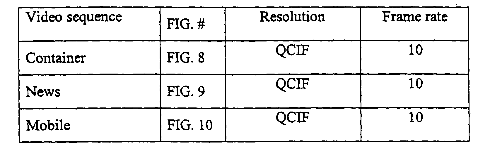
FIGS. 8-18 show test results of the Telenor encoder codec with and without
AMA in a variety of video sequences, resolutions, and frame rates, as described in Table 2.
These figures show rate-distortion ("RD") plots for each case. The "Anchor" curve shows
RD points from optimized H.263+ (FIGS. 8 and 9 only). The "Telenor 1/2+b" curve shows
Telenor with 1/2-pel vectors and bilinear interpolation (the "classical case"). The "Telenor
1/3" curve shows the current Telenor proposal (the "Telenor encoder"). The
"Telenor+AMA+c" curve shows the Telenor encoder with the full-search strategy of the
present invention. The" Telenor +FSAMA+c", as shown in FIGS. 15-17, shows the current
Telenor encoder with the fast-search strategy. (Unless otherwise specified, the full-search
version of AMA was the encoder strategy used in the experiments.) All of the test results
were cross-checked at the encoder and decoder. These results show that with AMA the gains
in peak signal-to-noise ratio ("PSNR") can be as high as 1 dB over H26L, and even higher
over the classical case.

The video sequences are commonly used by the video coding community,
except for "Paris Shaked." The latter is a synthetic sequence obtained by shifting the well-known
sequence "Paris" by a motion vector whose X and Y components take a random value
within [-1,1]. This synthetic sequence simulates small movements caused by a hand-held
camera in a typical video phone scene.
Comparison Of Full-Search And Fast-Search AMA
The experimental results shown in FIGS. 16 and 17 demonstrate that the
encoder performance with fast-search ("Telenor FSAMA+c") and full-search ("Telenor
AMA+c") strategies for AMA is practically the same. This is true because the fast-search
strategies exploit the convexity of the RD cost curve in the sub-pixel velocity space. In other
words, since the shape of the RD cost follows a smooth convex curve, its minimum should
be easy to find with some smart fast-search schemes that descend down the curve.
Combining AMA And Multiple Reference Frames
In the plot shown in FIG. 18, the curves labeled "1r" used only one reference
frame for the motion compensation, so these curves are the same as those presented in FIG.
10. The curves labeled "5r" used five reference frames.
The experiments show that the gains with AMA add to those obtained using
multiple reference frames. The gain from AMA in the one-reference case can be measured
by comparing the green and pink curves, and the gain in the five-reference case can be
measured between the blue and red curves.
It should be noted that the present invention may be implemented at the
frame level so that different frames could use different motion accuracies, but within a frame
all motion vectors would use the same accuracy. Preferably in this embodiment the motion
vector accuracy would then be signaled only once at the frame layer. Experiments have
shown that using the best, fixed motion accuracy for the whole frame should also produce
compression gains as those presented here for the macroblock-adaptive case.
In another frame-based embodiment the encoder could do motion
compensation on the entire frame with the different vector accuracies and then select the best
accuracy according to the RD criteria. This approach is not suitable for pipeline, one-pass
encoders, but it could be appropriate for software-based or more complex encoders. Still
another fame-based embodiment the encoder could use previous statistics and/or formulas
to predict what will be the best accuracy for a given frame (e.g., the formulas in set forth in
the Ribas work or a variation thereof can be used). This approach would be well-suited for
one-pass encoders, although the performance gains would depend on the precision of the
formulas used for the prediction.
The terms and expressions which have been employed in the foregoing
specification are used therein as terms of description and not of limitation, and there is no
intention, in the use of such terms and expressions, of excluding equivalents of the
features shown and described or portions thereof, it being recognized that the scope of the
invention is defined and limited only by the claims that follow.