EP1073179A2 - Slotless stator winding and method for manufacturing such winding - Google Patents
Slotless stator winding and method for manufacturing such winding Download PDFInfo
- Publication number
- EP1073179A2 EP1073179A2 EP00115151A EP00115151A EP1073179A2 EP 1073179 A2 EP1073179 A2 EP 1073179A2 EP 00115151 A EP00115151 A EP 00115151A EP 00115151 A EP00115151 A EP 00115151A EP 1073179 A2 EP1073179 A2 EP 1073179A2
- Authority
- EP
- European Patent Office
- Prior art keywords
- peripheral side
- wire
- diagonal
- sheaf
- shape
- Prior art date
- Legal status (The legal status is an assumption and is not a legal conclusion. Google has not performed a legal analysis and makes no representation as to the accuracy of the status listed.)
- Granted
Links
Images





Classifications
-
- H—ELECTRICITY
- H02—GENERATION; CONVERSION OR DISTRIBUTION OF ELECTRIC POWER
- H02K—DYNAMO-ELECTRIC MACHINES
- H02K15/00—Processes or apparatus specially adapted for manufacturing, assembling, maintaining or repairing of dynamo-electric machines
- H02K15/04—Processes or apparatus specially adapted for manufacturing, assembling, maintaining or repairing of dynamo-electric machines of windings prior to their mounting into the machines
- H02K15/043—Processes or apparatus specially adapted for manufacturing, assembling, maintaining or repairing of dynamo-electric machines of windings prior to their mounting into the machines winding flat conductive wires or sheets
-
- H—ELECTRICITY
- H02—GENERATION; CONVERSION OR DISTRIBUTION OF ELECTRIC POWER
- H02K—DYNAMO-ELECTRIC MACHINES
- H02K3/00—Details of windings
- H02K3/04—Windings characterised by the conductor shape, form or construction, e.g. with bar conductors
-
- H—ELECTRICITY
- H02—GENERATION; CONVERSION OR DISTRIBUTION OF ELECTRIC POWER
- H02K—DYNAMO-ELECTRIC MACHINES
- H02K3/00—Details of windings
- H02K3/46—Fastening of windings on the stator or rotor structure
- H02K3/47—Air-gap windings, i.e. iron-free windings
-
- Y—GENERAL TAGGING OF NEW TECHNOLOGICAL DEVELOPMENTS; GENERAL TAGGING OF CROSS-SECTIONAL TECHNOLOGIES SPANNING OVER SEVERAL SECTIONS OF THE IPC; TECHNICAL SUBJECTS COVERED BY FORMER USPC CROSS-REFERENCE ART COLLECTIONS [XRACs] AND DIGESTS
- Y10—TECHNICAL SUBJECTS COVERED BY FORMER USPC
- Y10T—TECHNICAL SUBJECTS COVERED BY FORMER US CLASSIFICATION
- Y10T29/00—Metal working
- Y10T29/49—Method of mechanical manufacture
- Y10T29/49002—Electrical device making
- Y10T29/49009—Dynamoelectric machine
Definitions
- the present invention relates to a stator winding which is suitable for use in a rotating electrical machine such as an electric motor or generator, and more specifically which is suitable for use in a slotless stator of a high speed rotating electrical machine, and to a manufacturing method therefor.
- FIG. 13 is a perspective view showing an end portion of a slotless stator.
- a plurality of coil segments 103 are secured to an inner peripheral face of a stator core 101.
- These coil segments 103 bear an approximate quadrilateral shape with rounded corners. When these coil segments 103 are used, this gives a construction, as can be seen from FIG. 13, where one side 105 of the quadrilateral shape is exposed from the edge portion of the stator core 101.
- the number of turns of the coil increases accordingly. Moreover, the less the number of poles the longer the span length exposed from the stator end. Furthermore, in order to cope with a high output brings the requirement for arranging conductors compatible with high currents. In such a case, the size of the coil in the axial direction or in the diametral direction is increased, so that the rotating electrical machine itself is enlarged. That is to say, there is the problem that when the conductor amount is increased to realize the high output, the rotating electrical machine is enlarged.
- FIG. 15 shows a band shape coil 111 formed by sequentially aligning rhombic shape turns.
- FIG. 16 shows a cylindrical shape coil 113 formed by rolling the band shape coil 111 of FIG. 15. With such a cylindrical shape coil 113, since apexes of the rhombic shapes are located at opposite ends of the cylindrical body, the amount of windings exposed from the stator can be kept to a minimum.
- the band shape coil comprising rhombic shape turns is formed from single wires, and is not possible to make this a multi-layered cylindrical coil which is a necessity in order to obtain a high output. In this case also even if this is parallel connected, phase matching is difficult, and there is the problem that if these are laminated in several layers, the coil thickness increases.
- the present invention takes into consideration the above problems with the object of providing a slotless stator which addresses the realization of high output and also miniaturization. Moreover, it is an object to provide a method of manufacturing a stator winding which is simple and has good formability.
- the stator winding of the present invention is characterized in being a hollow cylindrical body formed by: forming turns by winding a wire sheaf of a plurality of fine wires composed of conductors bundled together, through one turn in an approximate rhombic shape; forming approximate rhombic shape coil segments comprising a continuous length of the wire sheaves by winding and arranging a plurality of the turns so as to be sequentially shifted continuously in the direction of one diagonal of the rhombic shape, forming a band shape body using a plurality of the coil segments with these coil segments sequentially shifted in the direction of the one diagonal and so as to be adjacent to each other, and rolling the band shape body into a cylindrical shape.
- the coil is formed from a wire sheaf comprising a plurality of fine wires, then compared to a coil formed from a single wire, this can be made to cope with higher speed rotation. Moreover, with the wire sheaf, by pressing this using a press, an increase in the thickness of the coil can be avoided, and by twisting together, circulating current losses are reduced.
- the wire sheaf is characterized in that one end portion of opposite end portions of the respective turns which are located in the direction of an other diagonal orthogonal to the direction of the one diagonal is wound from an inner peripheral side of the hollow cylindrical body to an outer peripheral side, and an other end portion of the opposite end portions of the respective turns, is wound from the outer peripheral side to the inner peripheral side.
- the respective turns are characterized in that opposite end portions which are located in the direction of an other diagonal orthogonal to the direction of the one diagonal, have bent back portions which proceed so as to project to an outside of the turn, and then return back in an approximate U-shape and proceed so as to return to an inside.
- bent back portions By locating the bent back portions on the end portions of the hollow cylindrical body, these bent back portion face in the direction of the other diagonal of the rhombic shape, that is to say in the longitudinal (axis) direction of the hollow cylindrical body.
- the bent back portions can be compactly arranged around the circumferential direction of the hollow cylindrical body, so that a plurality of turns can be closely wound. Consequently, even if the number of turns is increased, the bent back portions are laminated side by side, and these bent back portions are not exposed extending in the radial direction or the axial direction.
- the respective turns are arranged in a condition touching adjacent turns. In this way, a winding wound at a high density can be formed.
- two sides located on one side of the other diagonal are arranged on an inner peripheral side of the hollow cylindrical body, and the other two sides opposite to the two sides located on the one side are arranged on an outer peripheral side of the hollow cylindrical body.
- the two sides of the coil segment which are arranged on the inner peripheral side of the hollow cylindrical body are abutted in the circumferential direction against the two sides which are arranged on the inner peripheral side of the adjacent coil segment, and the respective coil segments are arranged sequentially shifted while being overlapped so as to radially overlap the two sides of the adjacent coil segments, which are arranged on the outer peripheral side.
- the two sides which are arranged on the inner peripheral side of the respective coil segments are uniformly arranged in the circumferential direction. Furthermore, the two sides which are arranged on the outer peripheral side of the respective coil segments overlap the two sides arranged on the inner peripheral side of the adjacent coil segment, in the radial direction of the hollow cylindrical body. In so doing, the respective coil segments are arranged in an alternately overlapped fashion. As a result, the plurality of coil segments are closely overlapped in the circumferential direction and the diametral direction.
- one end side thereof is bent from the inner peripheral side of the hollow cylindrical body towards the outer peripheral side, and/or the other end side is bent from the outer peripheral side towards the inner peripheral side.
- the bent back portions are bent from the inner peripheral side (outer peripheral side) to the outer peripheral side (inner peripheral side), the bent back portions can be arranged closely in the circumferential direction. As a result, the respective turn sets can be arranged sequentially and in close contact in the circumferential direction. That is to say, even if the number of turns of increased, the winding is not enlarged in the axial direction and the diametral direction.
- the wire sheaf is twisted at least one turn in a helical form within a range of one side of the respective approximate rhombic shape turns.
- Twisting in a helical shape gives a construction the same as a Litz wire used for example in high frequency transformers. Hence the electromotive voltage difference which is produced in the respective strands in the wire sheaf forming the turns can be reduced, and the generation of unnecessary losses of for example circulating currents can be suppressed.
- the wire sheaf has an approximately rectangular shape cross-section.
- wire sheaves having rectangular cross-sections When wire sheaves having rectangular cross-sections are arranged adjacent to each other, these wire sheaves can be arranged in a close contact condition, thereby increasing the conductor space factor of the coil segment.
- the fine wires have a distorted circular cross-section with linear portions, and adjacent fine wires are contacted at the linear portions.
- the turn forming step is characterized in incorporating a bent back portion forming step for forming bent back portions at opposite end portions of the respective turns which are located in the direction of the other diagonal orthogonal to the direction of the one diagonal, which proceeds so as to project to an outside of the turn, and then returns back in an approximate U-shape and proceeds so as to return to an inside.
- the turn forming step incorporates a press step for pressing the wire sheaf so that adjacent fine wires are closely contacted.
- the respective fine wires constituting the wire sheaf are deformed to a close contact condition. Furthermore, by keeping the respective fine wires in a close contact condition in this way, the cross-sectional shape of the wire sheaf can be stably maintained.
- the press step incorporates a step for forming the wire sheaf so that the wire sheaf has an approximately rectangular cross-section.
- FIG. 1 is a cross-sectional view showing a rotating electrical machine provided with a stator winding being one embodiment of the present invention.
- FIG. 2 is a sectional view on the section line II-II of FIG. 1.
- FIG. 1 A rotating electrical machine 3 incorporating a slotless stator 1 is shown in FIG. 1. This is suitable for use in a high speed rotating electrical machine which is used for example at several kW to several tens of kW, and at rotational speeds above several ten thousand rpm.
- the outer shape is formed from a casing 5, and a rotor 7 is rotatably arranged via bearings 9 along a central axis of the casing 5.
- a permanent magnet 11 serving as magnetic field generating device is incorporated therein.
- This permanent magnet 11 is constructed so that p (where p is an even number of two or more) magnetic poles for generating a magnetic flux in the radial direction, are formed on the outer surface of the rotor 7.
- a rare earth magnet such as a Sm-Co, Nd-Fe-B sintered magnet is suitable.
- the slotless stator 1, as shown in FIG. 1 is arranged around the rotor 7, forming a small gap 13.
- the slotless stator 1 is one wherein slots for securing windings are not formed.
- the slotless stator 1 comprises a winding (stator winding, or slotless stator winding) 15 positioned on the rotor 7 side, and a stator core 17 positioned on the casing 5 side.
- the stator core 17 is in the form of a hollow cylindrical shape, and is secured so that the outer peripheral face of the stator core 17 is contacted with the inner peripheral face of the casing 5.
- the stator core 17 is constructed by laminating a large number of ring shaped electrical steel plates in the plate thickness direction.
- the stator core 17 has an inner peripheral face which is a cylindrical surface not formed with slots.
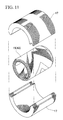
- the stator core 17 may also be a divided configuration. For example, as shown in FIG. 11, this may be in a two piece form. Of course, this may also be three or more pieces.
- the winding 15, as with the stator core 17, is a hollow cylindrical shape, and is secured by means of an insulation layer 19 so that the outer peripheral face of the winding 15 faces the inner face peripheral face of the stator core 17. With the winding 15, the end portions are connected by connection wires via a bus bar 21.
- FIG. 3 shows a condition where the hollow cylindrical shape stator winding-15 has been developed into a plane.
- This band shape winding 15 developed into a plane comprises a plurality of coil segments 23.
- the coil segments 23 are formed from a wire sheaf 27 (refer to FIG. 6) with a plurality of magnet wires (fine wires) 25 composed of conductors bundled together.
- the magnet wires 25 are formed with an insulation layer on the surface, and the strand outer diameter is preferable less than 1mm.
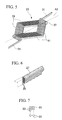
- the coil segments 23 are constructed by arranging a plurality of single turns 29 formed by winding the wire sheaf 27 once around an approximate rhombic shape. That is to say, the respective turns 29 are wound and arranged so as to be continuously and sequentially shifted in the direction of a diagonal A1 (one diagonal) of a rhombic shape extending in the left and right direction in the figure.
- the respective turns 29 are arranged contacting with adjacent turns 29 in a close contact condition.
- a Litz wire may be used in order to reduce the skin effect at high frequencies.
- the turns 29 have the following characteristics for the shape.
- Opposite end portions 35 which are located in the direction of a diagonal (other diagonal) A2 which extends in the vertical direction in the figure, orthogonal to the direction of the one diagonal A1 have bent back portions 37.
- These bent back portions 37 are formed proceeding so as to project on the other diagonal A2 towards the outside of the turns 29, and then return back in an approximate U-shape and proceed so as to return on the other diagonal A2 towards the inside of the turns 29. That is to say, the bent back portions 37 in this embodiment are in an approximately 180° bent hair pin shape.
- bent back portions 37 are bent from the lower (upper) side in the figure to the upper (lower) side. That is to say, as described later, when the coil segments 23 are rolled to give a hollow cylindrical body, these are bent from the inner (outer) peripheral side of the hollow cylindrical body towards the outer (inner) peripheral side.
- the bent back portions 37 are wound from the inner peripheral side of the hollow cylindrical body to the outer peripheral side, and at the other end portion of the opposite end portions of the respective turns 29, are wound from the outer peripheral side to the inner peripheral side.
- two sides 39 of one set are arranged so as to be on a lower side with respect to two sides 41 of the other set. That is to say, when the coil segment 23 is rolled into a hollow cylindrical body, then of the four sides of the approximate rhombic shape coil segments 23, the two sides 39 located on one side of the other diagonal A2 are arranged at the outer peripheral side of the hollow cylindrical body, and the other two sides 41 facing the two sides 39 located on the one side, are arranged on the inner peripheral side of the hollow cylindrical body.
- the coil segment 23 is formed from a continuous wire sheaf 27, by continuously winding a plurality of turns 29 (refer to FIG. 4 and FIG. 6). Consequently, a pair of terminals 31 for electrical connection are provided for each coil segment 23.
- FIG. 4 is shown a coil segment where the turns 29 are wound as 12.5 turns.
- the number of windings is not limited to this and may be appropriately changed in accordance with the intended use.
- the wire sheaf 27 is constructed with a plurality of magnetic wires 25 bundled together, and as will be apparent from FIG. 6, this wire sheaf 27 has a rectangular shape in cross-section. Furthermore, the wire sheaf 27 is twisted in helical form. With this twisting, it is desirable to apply at least one twist, that is at least 360°, within the range of one side of the rhombic shape turn 29.
- each of the magnet wires 25 constituting the wire sheaf 27 is made in a distorted circular cross-section shape. More specifically, these are an approximate square shape having linear portions 33 and bearing rounded corners. Since the magnet wires 25 have this cross-sectional shape, then at the respective linear portions 33, the adjacent magnet wires 25 are contacted in a close contact condition.
- a band shape body as shown in FIG. 3 is formed. This band shape body is then rolled into a cylindrical shape as shown in FIG. 9 to give a hollow cylindrical body 43.
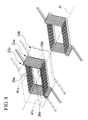
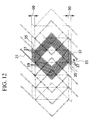
- each coil segment 23 is overlapped as follows. That is to say, each coil segment 23, as shown in FIG. 8 is arranged sequentially shifted while being overlapped in the direction of the one diagonal A1. More precisely, two sides 39a of the coil segment 23a arranged at the bottom side (left side) in the figure are arranged adjacent in the direction of the one diagonal A1 to two sides 39b arranged at the bottom side (left side) in the figure of the adjacent coil segment 23b. Furthermore, these are arranged so as to overlap in the vertical direction, the two sides 41c located at the upper side in the figure, of the adjacent coil segment 23c.
- the two sides 39 of the coil segments 23, which are arranged on the outer peripheral side are abutted in the circumferential direction against the two sides 39 which are arranged on the outer peripheral side of the adjacent coil segments 23, and are arranged so as to radially overlap the two sides 41 of the adjacent coil segments 23, which are arranged on the inner peripheral side.
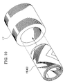
- the winding 15 made as the cylindrical hollow body 43 (refer to FIG. 9) comprising the plurality of coil segments 23 constructed in the above manner, is inserted inside the stator core 17 as shown in FIG. 10 and secured.
- the plurality of magnet wires 25 are bundled together to form the wire sheaf 27 (refer to FIG. 6).
- the wire sheaf 27 is then wound in an approximately rhombic shape to form a plurality of turns (refer to FIG. 4).
- the wire sheaf 27 is wound so as to form the aforementioned bent back portions 37.
- the wire sheaf 27 is pressed with a press so that the adjacent magnet wires 25 are closely packed together. Moreover, as shown in FIG. 7, it is desirable to form the wire sheaf 27 with a press so as to have a rectangular shape in cross-section.
- the wire sheaves 27 are twisted at least once within the range of one side of the approximate rhombic shape turns 29.
- a coil segment 23 comprising a continuous length of the wire sheaf 27 is formed by arranging a plurality of the respective turns 29 so as to be sequentially shifted in the direction of the one diagonal A1 (refer to FIG. 4).
- the hollow cylindrical body 43 (refer to FIG. 9) is formed by forming the band shape body (refer to FIG. 8) using a plurality of the coil segments 23 with these coil segments 23 sequentially shifted and overlapped in the direction of the one diagonal A1, and then rolling the band shape body into a cylindrical shape.
- the bent back portions 37 are provided in the winding 15, and these bent back portions 37 are bent in a U-shape in the longitudinal direction of the hollow cylindrical body 43 to give the hair pin shape, and become the end portions of the hollow cylindrical body 43. Therefore, compared to the conventional winding where the winding which is exposed from the stator core extends in the circumferential direction, the amount of magnet wire 25 which is used can be considerably reduced. Since in this way the overall length of the magnet wires 25 is shortened, the direct current resistance of the winding 15 can be reduced, and hence heating of the winding 15 due to joule heating can be suppressed.
- the respective turns 29 can be more tightly arranged. That is to say, since the bent back portions 37 are bent in the radial direction of the hollow cylindrical body 43, these bent back portions 37 can be arranged in close contact in the circumferential direction. As a result, the respective turns 29 also can be closely arranged in the circumferential direction, and even if the number of turns increases, there is no overlapping of the wire sheaves 27 in the radial or axial directions.
- the one set of two sides 39 can be arranged on the outer peripheral side, and the other set of two sides 41 can be arranged on the inner peripheral side. Consequently, the wire sheaves 27 can be arranged evenly and close together on both the inner peripheral side and the outer peripheral side of the hollow cylindrical body.
- the construction is such that the two sides 39 of the one coil segment coil segment 23, on the outer peripheral side are positioned side by side in the circumferential direction relative to the two sides 39 of the other coil segment 23, on the outer peripheral side, and these are positioned abutting in the radial direction against the two sides 41 on the inner peripheral side of the other coil segment 23. Therefore, the wire sheaves can be arranged evenly and close together in the circumferential and radial directions. Consequently, a sufficiently high current density can be maintained, and a high output thus achieved.
- the cross-sectional shape of the wire sheaf 27 is an approximate rectangular shape due to pressing, when the plurality of wire sheaves 27 are arranged in a line, these can be arranged so as to have no gap, rather than with the case where a wire sheaf with strands of simple circular cross-section are bundled together. That is, the conductor space factor per one side of the coil segment 23 can be increased.
- the conductors can be more densely arranged inside the wire sheaf 27 than with the construction where magnet wires having a circular cross-section is simply bundled together. Hence a higher current density can be obtained.
- wire sheaf 27 is made by twisting in a helical shape, an effect the same as conductor reversal in a Litz wire is obtained. In particular this occurs when the rotor 7 of the rotating electrical machine 3 is rotated at high speed. Hence eddy current losses and circulating current losses can be significantly reduced.
- the bent back portions are provided at opposite ends of the respective turns, the respective turns can be tightly wound. As a result, a high current value can be realized, and a high output from the rotating electrical machine can be achieved.
- bent back portions can be arranged sequentially aligned in the circumferential direction, a size increase in the axial direction and the diametral direction due to an increase in the amount of conductors can be avoided. Hence miniaturization of the rotating electrical machine can be realized.
- the cross-sectional shape of the wire sheaf can be stably maintained. Therefore the degree of freedom at the time of winding manufacture can be considerably increased.
- stator winding which copes with high output and miniaturization
- turns formed by winding a wire sheaf of a plurality of fine wires bundled together, in an approximate rhombic shape are arranged so as to be sequentially shifted in the direction of one diagonal of the rhombic shape, to thereby form an approximate rhombic shape coil segment comprising a continuous length of the wire sheaf
- a plurality of coil segments are then sequentially shifted and overlapped on one diagonal to form a band shape body, and a hollow cylindrical body is then formed by rolling the band shape body into a circular shape.
- the winding is characterized in that with each turn, opposite end portions located in the direction of an other diagonal orthogonal to the direction of the one diagonal have U-shape bent back portions.
Landscapes
- Engineering & Computer Science (AREA)
- Power Engineering (AREA)
- Manufacturing & Machinery (AREA)
- Windings For Motors And Generators (AREA)
- Manufacture Of Motors, Generators (AREA)
Abstract
Description
Claims (15)
- A stator winding for use in a rotating electric machine having a slotless stator, being a hollow cylindrical body formed by:forming turns by winding a wire sheaf of a plurality of fine wires composed of conductors bundled together, through one turn in an approximate rhombic shape;forming approximate rhombic shape coil segments comprising a continuous length of said wire sheaf by winding and arranging a plurality of said turns so as to be sequentially shifted continuously in the direction of one diagonal of said rhombic shape,forming a band shape body using a plurality of said coil segments with these coil segments sequentially shifted in the direction of said one diagonal and so as to be adjacent to each other, and rolling said band shape body into a cylindrical shape.
- A stator winding according to claim 1, wherein with said wire sheaf, one end portion of opposite end portions of said respective turns which are located in the direction of an other diagonal orthogonal to the direction of said one diagonal is wound from an inner peripheral side of said hollow cylindrical body to an outer peripheral side, and an other end portion of said opposite end portions of said respective turns, is wound from the outer peripheral side to the inner peripheral side.
- A stator winding according to either one of claim 1 and claim 2, wherein with said respective turns, opposite end portions which are located in the direction of an other diagonal orthogonal to the direction of said one diagonal, have bent back portions which proceed so as to project towards an outside of said turn, and then return back in an approximate U-shape and proceed so as to return towards an inside.
- A stator winding according to any one of claim 1 through claim 3, wherein said respective turns are arranged in a condition touching adjacent turns.
- A stator winding according to any one of claim 1 through claim 4, wherein of the four sides of said approximate rhombic shape coil segments, two sides located on one side of said other diagonal are arranged on an inner peripheral side of said hollow cylindrical body,and the other two sides opposite to the two sides located on said one side are arranged on an outer peripheral side of said hollow cylindrical body.
- A stator winding according to claim 5, wherein the two sides of the coil segment which are arranged on the inner peripheral side are abutted in the circumferential direction against said two sides which are arranged on the inner peripheral side of the adjacent coil segment,and the respective coil segments are arranged sequentially shifted while being overlapped so as to radially overlap said two sides of the adjacent coil segments, which are arranged on the outer peripheral side.
- A stator winding according to any one of claim 2 through claim 6, wherein said bent back portions are bent from the inner peripheral side of said hollow cylindrical body towards the outer peripheral side, or from the outer peripheral side towards the inner peripheral side.
- A stator winding according to any one of claim 1 through claim 7, wherein said wire sheaf is twisted at least one turn in a helical form within a range of one side of the respective approximate rhombic shape turns.
- A stator winding according to any one of claim 1 through claim 8, wherein said wire sheaf has an approximately rectangular shape cross-section.
- A stator winding according to any one of claim 1 through claim 9, wherein said fine wires have a distorted circular cross-section with linear portions, and adjacent fine wires are contacted at said linear portions.
- A method of manufacturing a stator winding wherein with a method of manufacturing a stator winding used in a rotating electric machine having a slotless stator, which incorporates:a turn forming step for forming turns by winding a wire sheaf of a plurality of fine wires composed of conductors bundled together, through one turn in an approximate rhombic shape;a coil segment forming step for forming coil segments comprising a continuous length of said wire sheaf by winding and arranging a plurality of said turns so as to be sequentially shifted continuously in the direction of one diagonal of said rhombic shape; anda hollow cylindrical body forming step for forming a band shape body using a plurality of said coil segments by overlapping these coil segments so as to be sequentially shifted in the direction of said one diagonal and adjacent to each other, and rolling said band shape body into a hollow cylindrical shape,said turn forming step includes a step where with said wire sheaf, one end portion of opposite end portions of said respective turns which are located in the direction of an other diagonal orthogonal to the direction of said one diagonal is wound from an inner peripheral side of said hollow cylindrical body to an outer peripheral side, and an other end portion of said opposite end portions of said respective turns, is wound from the outer peripheral side to the inner peripheral side.
- A method of manufacturing a stator winding according to claim 11, wherein said turn forming step incorporates a bent back portion forming step for forming bent back portions at opposite end portions of said respective turns which are located in the direction of the other diagonal orthogonal to the direction of said one diagonal, which proceeds so as to project towards an outside of said turn, and then returns back in an approximate U-shape and proceeds so as to return towards an inside.
- A method of manufacturing a stator winding according to either one of claim 11 and claim 12, wherein said turn forming step incorporates a press step for pressing said wire sheaf so that adjacent fine wires are closely contacted.
- A method of manufacturing a stator winding according to claim 13, wherein prior to said press step there is provided a step for twisting said wire sheaf at least one turn in a helical form within a range of one side of said approximate rhombic shape turn.
- A method of manufacturing a stator winding according to either one of claim 13 and claim 14, wherein said press step incorporates a step for forming said wire sheaf so that said wire sheaf has an approximately rectangular cross-section.
Applications Claiming Priority (2)
| Application Number | Priority Date | Filing Date | Title |
|---|---|---|---|
| JP21139599A JP4421018B2 (en) | 1999-07-26 | 1999-07-26 | Slotless stator winding and manufacturing method thereof |
| JP21139599 | 1999-07-26 |
Publications (3)
| Publication Number | Publication Date |
|---|---|
| EP1073179A2 true EP1073179A2 (en) | 2001-01-31 |
| EP1073179A3 EP1073179A3 (en) | 2003-09-10 |
| EP1073179B1 EP1073179B1 (en) | 2010-05-05 |
Family
ID=16605270
Family Applications (1)
| Application Number | Title | Priority Date | Filing Date |
|---|---|---|---|
| EP00115151A Expired - Lifetime EP1073179B1 (en) | 1999-07-26 | 2000-07-12 | Slotless stator winding and method for manufacturing such winding |
Country Status (4)
| Country | Link |
|---|---|
| US (1) | US6791224B1 (en) |
| EP (1) | EP1073179B1 (en) |
| JP (1) | JP4421018B2 (en) |
| DE (1) | DE60044324D1 (en) |
Cited By (11)
| Publication number | Priority date | Publication date | Assignee | Title |
|---|---|---|---|---|
| WO2004045048A1 (en) * | 2002-11-13 | 2004-05-27 | Honda Giken Kogyo Kabushiki Kaisha | Slotless rotary electric machine and manufacturing method of coils for such a machine |
| WO2004098025A1 (en) * | 2003-04-28 | 2004-11-11 | Danfoss A/S | Slotless stator with an expanding member to fix the winding |
| EP2180581A2 (en) | 2008-10-23 | 2010-04-28 | Electromag SA | Brushless DC electric motor |
| US7990013B2 (en) * | 2008-06-23 | 2011-08-02 | Korea Electronics Technology Institute | Slotless motor |
| AT511024A2 (en) * | 2009-10-06 | 2012-08-15 | Seiko Instr Inc | Dynamoelectric machine and handpiece for dental or medical treatment |
| AT511025A2 (en) * | 2009-10-06 | 2012-08-15 | Seiko Instr Inc | Dynamoelectric machine and handpiece for dental or medical treatment |
| EP2642636A1 (en) * | 2012-03-21 | 2013-09-25 | Maxon Motor AG | Hollow cylinder iron-free coil |
| CN105186748A (en) * | 2015-07-31 | 2015-12-23 | 浙江鼎安机械制造有限公司 | Stator winding structure of radial coreless armature permanent magnet motor and motor having the same |
| WO2016110549A1 (en) * | 2015-01-07 | 2016-07-14 | Universite Catholique De Louvain | Winding for an electrical machine |
| EP3171497A1 (en) | 2015-11-19 | 2017-05-24 | Lakeview Innovation Ltd. | Two-pole brush-commuted dc electric motor |
| CN110661387A (en) * | 2018-06-29 | 2020-01-07 | 上海鸣志电器股份有限公司 | A stranded wire method for air-gap windings |
Families Citing this family (21)
| Publication number | Priority date | Publication date | Assignee | Title |
|---|---|---|---|---|
| WO2002049050A1 (en) * | 2000-12-11 | 2002-06-20 | Koninklijke Philips Electronics N.V. | Band coil |
| US7506280B2 (en) * | 2004-11-12 | 2009-03-17 | Tabtronics, Inc. | Magnetic winding and method of making same |
| JP2006340583A (en) * | 2005-06-06 | 2006-12-14 | Masaaki Iwatani | Coil and coil component |
| DE102005051059B4 (en) * | 2005-10-25 | 2016-09-15 | Maxon Motor Ag | Method for producing an electric motor and electric motor with multilayer diamond-shaped individual coils of wire |
| DE102005054863A1 (en) * | 2005-11-21 | 2007-05-24 | Robert Bosch Gmbh | Folded loop winding for a stand |
| JP4933169B2 (en) * | 2006-06-30 | 2012-05-16 | 地方独立行政法人北海道立総合研究機構 | Coil component and manufacturing method thereof |
| JP5284979B2 (en) * | 2006-12-28 | 2013-09-11 | レスメド・モーター・テクノロジーズ・インコーポレーテッド | Coil winding method and structure for slotless stator in motor |
| CN101022229B (en) * | 2007-03-27 | 2013-01-02 | 南京汽轮电机(集团)有限责任公司 | Stator winding end partial unit connecting method |
| JP4917479B2 (en) * | 2007-05-31 | 2012-04-18 | 公明 岩谷 | Coil manufacturing method |
| CN101483361B (en) * | 2008-01-11 | 2011-12-07 | 德昌电机(深圳)有限公司 | Stator winding construction and winding method for slotless motor stator winding, and stator construction with the winding construction |
| JP4502041B2 (en) * | 2008-04-24 | 2010-07-14 | 株式会社デンソー | Stator for rotating electric machine and method for manufacturing the same |
| ES2423801T3 (en) | 2010-12-15 | 2013-09-24 | Infranor Holding S.A. | Synchronous motor with permanent magnets |
| JP5729368B2 (en) * | 2012-10-31 | 2015-06-03 | トヨタ自動車株式会社 | Segment coil manufacturing method |
| US20160013693A1 (en) * | 2014-07-08 | 2016-01-14 | Hamilton Sundstrand Corporation | Strand layout for reduced ac winding loss |
| US20160013692A1 (en) * | 2014-07-08 | 2016-01-14 | Hamilton Sundstrand Corporation | Stator winding assembly |
| KR101972869B1 (en) | 2017-04-25 | 2019-04-26 | 엘씨 텍(주) | Manufacturing method for stator assembly of the slotless motor and devices for the same |
| CN109327093B (en) * | 2017-08-01 | 2024-03-22 | 上海鸣志电器股份有限公司 | Nested winding for gearless motor |
| JP7255383B2 (en) * | 2018-07-25 | 2023-04-11 | 株式会社デンソー | Rotating electric machine |
| JP7181781B2 (en) * | 2018-12-10 | 2022-12-01 | 株式会社Soken | Rotating electric machine, power converter, and manufacturing method of rotating electric machine |
| WO2023163136A1 (en) * | 2022-02-24 | 2023-08-31 | 株式会社デンソー | Coil body, armature, and rotary electric machine |
| JP7782472B2 (en) * | 2022-02-24 | 2025-12-09 | 株式会社デンソー | Coil body, armature and rotating electric machine |
Family Cites Families (15)
| Publication number | Priority date | Publication date | Assignee | Title |
|---|---|---|---|---|
| GB1242421A (en) * | 1967-09-18 | 1971-08-11 | Interelectric Ag | Electrical machine cylindrical coil winding |
| BE793731A (en) * | 1972-01-05 | 1973-05-02 | English Electric Co Ltd | ELECTROGENERATORS |
| US3995364A (en) * | 1973-09-14 | 1976-12-07 | Interelectric Aktiengesellschaft | Method for manufacturing a tubular-shaped multilayer coil for electrical machines |
| DE2511567A1 (en) * | 1975-03-17 | 1976-09-30 | Teldix Gmbh | Brushless high output rotating electrical machine - has non-magnetic and non-conducting stator body |
| JPS5125758A (en) * | 1974-08-27 | 1976-03-02 | Tamagawa Seiki Co Ltd | Denkyosunikukoiruno makisenseizohoho |
| JPS5744753Y2 (en) * | 1975-03-15 | 1982-10-02 | ||
| US4260924A (en) * | 1978-09-27 | 1981-04-07 | Westinghouse Electric Corp. | Conductor bar for dynamoelectric machines |
| US4481438A (en) * | 1982-09-13 | 1984-11-06 | Electric Power Research Institute, Inc. | High voltage electrical generator and windings for use therein |
| EP0150070A3 (en) * | 1984-01-19 | 1986-06-04 | Papst-Motoren GmbH & Co. KG | Commutatorless direct-current motor with a ironless stator winding |
| DE3621095A1 (en) * | 1986-06-24 | 1988-01-07 | Thomson Brandt Gmbh | METHOD FOR PRODUCING A FLAT COIL TAPE |
| IT1228922B (en) * | 1989-03-01 | 1991-07-09 | Sirten | ROPE ELECTRIC CONDUCTOR WITH FLAT CORE. |
| US5200661A (en) * | 1989-12-15 | 1993-04-06 | Shramo Daniel J | Slotless, brushless, large air gap electric motor |
| US5197180A (en) * | 1991-09-13 | 1993-03-30 | Faraday Energy Foundation | Method for making an electric motor winding |
| JP3598581B2 (en) * | 1995-05-19 | 2004-12-08 | 株式会社デンソー | Rotor coil of generator and method of manufacturing the same |
| CN1200591A (en) * | 1997-05-26 | 1998-12-02 | 株式会社电装 | car generator |
-
1999
- 1999-07-26 JP JP21139599A patent/JP4421018B2/en not_active Expired - Fee Related
-
2000
- 2000-07-12 DE DE60044324T patent/DE60044324D1/en not_active Expired - Lifetime
- 2000-07-12 EP EP00115151A patent/EP1073179B1/en not_active Expired - Lifetime
- 2000-07-19 US US09/619,547 patent/US6791224B1/en not_active Expired - Fee Related
Cited By (22)
| Publication number | Priority date | Publication date | Assignee | Title |
|---|---|---|---|---|
| WO2004045048A1 (en) * | 2002-11-13 | 2004-05-27 | Honda Giken Kogyo Kabushiki Kaisha | Slotless rotary electric machine and manufacturing method of coils for such a machine |
| US7269890B2 (en) | 2002-11-13 | 2007-09-18 | Honda Giken Kogyo Kabushiki Kaisha | Slotless rotary electric machine and manufacturing method of coils for such a machine |
| WO2004098025A1 (en) * | 2003-04-28 | 2004-11-11 | Danfoss A/S | Slotless stator with an expanding member to fix the winding |
| US7990013B2 (en) * | 2008-06-23 | 2011-08-02 | Korea Electronics Technology Institute | Slotless motor |
| EP2180581A2 (en) | 2008-10-23 | 2010-04-28 | Electromag SA | Brushless DC electric motor |
| EP2180581A3 (en) * | 2008-10-23 | 2011-11-16 | Electromag SA | Brushless DC electric motor |
| AT511025B1 (en) * | 2009-10-06 | 2017-12-15 | Seiko Instr Inc | Dynamoelectric machine and handpiece for dental or medical treatment |
| AT511025A2 (en) * | 2009-10-06 | 2012-08-15 | Seiko Instr Inc | Dynamoelectric machine and handpiece for dental or medical treatment |
| AT511024B1 (en) * | 2009-10-06 | 2017-12-15 | Seiko Instr Inc | Dynamoelectric machine and handpiece for dental or medical treatment |
| AT511024A2 (en) * | 2009-10-06 | 2012-08-15 | Seiko Instr Inc | Dynamoelectric machine and handpiece for dental or medical treatment |
| EP2642636A1 (en) * | 2012-03-21 | 2013-09-25 | Maxon Motor AG | Hollow cylinder iron-free coil |
| US9509187B2 (en) | 2012-03-21 | 2016-11-29 | Maxon Motor Ag | Hollow-cylindrical coreless winding |
| US11239720B2 (en) | 2015-01-07 | 2022-02-01 | Universite Catholique De Louvain | Winding for an electrical machine |
| WO2016110549A1 (en) * | 2015-01-07 | 2016-07-14 | Universite Catholique De Louvain | Winding for an electrical machine |
| US11258323B2 (en) | 2015-01-07 | 2022-02-22 | Universite Catholique De Louvain | Winding for an electrical machine |
| EP3754813A1 (en) * | 2015-01-07 | 2020-12-23 | Universite Catholique De Louvain | Winding for an electrical machine |
| CN105186748A (en) * | 2015-07-31 | 2015-12-23 | 浙江鼎安机械制造有限公司 | Stator winding structure of radial coreless armature permanent magnet motor and motor having the same |
| CN105186748B (en) * | 2015-07-31 | 2023-09-19 | 浙江鼎安机械制造有限公司 | Stator winding structure of radial coreless permanent magnet motor and motor |
| EP3171498A1 (en) | 2015-11-19 | 2017-05-24 | Lakeview Innovation Ltd. | Two-pole brush-commuted dc electric motor |
| EP3171497A1 (en) | 2015-11-19 | 2017-05-24 | Lakeview Innovation Ltd. | Two-pole brush-commuted dc electric motor |
| CN110661387A (en) * | 2018-06-29 | 2020-01-07 | 上海鸣志电器股份有限公司 | A stranded wire method for air-gap windings |
| CN110661387B (en) * | 2018-06-29 | 2022-04-05 | 上海鸣志电器股份有限公司 | Wire stranding method for air gap winding |
Also Published As
| Publication number | Publication date |
|---|---|
| US6791224B1 (en) | 2004-09-14 |
| DE60044324D1 (en) | 2010-06-17 |
| JP2001037130A (en) | 2001-02-09 |
| EP1073179B1 (en) | 2010-05-05 |
| JP4421018B2 (en) | 2010-02-24 |
| EP1073179A3 (en) | 2003-09-10 |
Similar Documents
| Publication | Publication Date | Title |
|---|---|---|
| EP1073179B1 (en) | Slotless stator winding and method for manufacturing such winding | |
| US6894418B2 (en) | Nested stator coils for permanent magnet machines | |
| JP5122685B2 (en) | Superconducting rotating electrical machine and stator for superconducting rotating electrical machine | |
| US20130278103A1 (en) | Stator used in an electrical motor or generator with low loss magnetic material and method of manufacturing a stator | |
| CN110492630B (en) | Rotary motor | |
| JP2000166152A (en) | Stator for vehicle alternator and method of manufacturing the same | |
| JP7442050B2 (en) | Coil, stator, rotor, motor and coil manufacturing method equipped with the same | |
| EP1766757A4 (en) | STATORIC CORE OF ELECTRODYNAMIC MACHINE, WITH MINI CAPS | |
| CN104620474B (en) | The stator of electric rotating machine | |
| US7646131B2 (en) | Permanent magnet synchronous machine with flat-wire windings | |
| WO2004045048A1 (en) | Slotless rotary electric machine and manufacturing method of coils for such a machine | |
| JPH0739097A (en) | Electric motor | |
| US20200295611A1 (en) | Electric machine with solid and stranded conductors | |
| JPWO2020255614A5 (en) | ||
| US9819238B2 (en) | Rotary electric machine having stator with coil conductors having different cross-sectional width | |
| JP2010041786A (en) | Stator windings and electric rotary machine | |
| JP2011223652A (en) | Rotating electric machine winding and rotating electric machine component member | |
| JP5072502B2 (en) | Rotating motor | |
| JP2006187164A (en) | Rotating electric machine | |
| US8933607B1 (en) | High efficiency air core motor-generator | |
| JP2004208464A (en) | Electric motor winding structure | |
| JP2009268221A (en) | Method of manufacturing stator coil | |
| WO2019225665A1 (en) | Electric motor, stator, and electric motor manufacturing method | |
| JP2001186728A (en) | Method of manufacturing stator for vehicle alternator | |
| JP6968215B2 (en) | Rotating machine |
Legal Events
| Date | Code | Title | Description |
|---|---|---|---|
| PUAI | Public reference made under article 153(3) epc to a published international application that has entered the european phase |
Free format text: ORIGINAL CODE: 0009012 |
|
| AK | Designated contracting states |
Kind code of ref document: A2 Designated state(s): AT BE CH CY DE DK ES FI FR GB GR IE IT LI LU MC NL PT SE |
|
| AX | Request for extension of the european patent |
Free format text: AL;LT;LV;MK;RO;SI |
|
| PUAL | Search report despatched |
Free format text: ORIGINAL CODE: 0009013 |
|
| AK | Designated contracting states |
Kind code of ref document: A3 Designated state(s): AT BE CH CY DE DK ES FI FR GB GR IE IT LI LU MC NL PT SE |
|
| AX | Request for extension of the european patent |
Extension state: AL LT LV MK RO SI |
|
| 17P | Request for examination filed |
Effective date: 20040123 |
|
| 17Q | First examination report despatched |
Effective date: 20040419 |
|
| AKX | Designation fees paid |
Designated state(s): CH DE FR GB LI NL SE |
|
| 17Q | First examination report despatched |
Effective date: 20040419 |
|
| GRAP | Despatch of communication of intention to grant a patent |
Free format text: ORIGINAL CODE: EPIDOSNIGR1 |
|
| GRAS | Grant fee paid |
Free format text: ORIGINAL CODE: EPIDOSNIGR3 |
|
| GRAA | (expected) grant |
Free format text: ORIGINAL CODE: 0009210 |
|
| AK | Designated contracting states |
Kind code of ref document: B1 Designated state(s): CH DE FR GB LI NL SE |
|
| REG | Reference to a national code |
Ref country code: GB Ref legal event code: FG4D |
|
| REG | Reference to a national code |
Ref country code: CH Ref legal event code: EP |
|
| REF | Corresponds to: |
Ref document number: 60044324 Country of ref document: DE Date of ref document: 20100617 Kind code of ref document: P |
|
| REG | Reference to a national code |
Ref country code: NL Ref legal event code: VDEP Effective date: 20100505 |
|
| PG25 | Lapsed in a contracting state [announced via postgrant information from national office to epo] |
Ref country code: NL Free format text: LAPSE BECAUSE OF FAILURE TO SUBMIT A TRANSLATION OF THE DESCRIPTION OR TO PAY THE FEE WITHIN THE PRESCRIBED TIME-LIMIT Effective date: 20100505 Ref country code: SE Free format text: LAPSE BECAUSE OF FAILURE TO SUBMIT A TRANSLATION OF THE DESCRIPTION OR TO PAY THE FEE WITHIN THE PRESCRIBED TIME-LIMIT Effective date: 20100505 |
|
| REG | Reference to a national code |
Ref country code: CH Ref legal event code: PL |
|
| PLBE | No opposition filed within time limit |
Free format text: ORIGINAL CODE: 0009261 |
|
| STAA | Information on the status of an ep patent application or granted ep patent |
Free format text: STATUS: NO OPPOSITION FILED WITHIN TIME LIMIT |
|
| 26N | No opposition filed |
Effective date: 20110208 |
|
| PG25 | Lapsed in a contracting state [announced via postgrant information from national office to epo] |
Ref country code: LI Free format text: LAPSE BECAUSE OF NON-PAYMENT OF DUE FEES Effective date: 20100731 Ref country code: CH Free format text: LAPSE BECAUSE OF NON-PAYMENT OF DUE FEES Effective date: 20100731 |
|
| REG | Reference to a national code |
Ref country code: DE Ref legal event code: R097 Ref document number: 60044324 Country of ref document: DE Effective date: 20110207 |
|
| PGFP | Annual fee paid to national office [announced via postgrant information from national office to epo] |
Ref country code: FR Payment date: 20110727 Year of fee payment: 12 |
|
| PGFP | Annual fee paid to national office [announced via postgrant information from national office to epo] |
Ref country code: GB Payment date: 20110706 Year of fee payment: 12 |
|
| GBPC | Gb: european patent ceased through non-payment of renewal fee |
Effective date: 20120712 |
|
| REG | Reference to a national code |
Ref country code: FR Ref legal event code: ST Effective date: 20130329 |
|
| PG25 | Lapsed in a contracting state [announced via postgrant information from national office to epo] |
Ref country code: FR Free format text: LAPSE BECAUSE OF NON-PAYMENT OF DUE FEES Effective date: 20120731 Ref country code: GB Free format text: LAPSE BECAUSE OF NON-PAYMENT OF DUE FEES Effective date: 20120712 |
|
| PGFP | Annual fee paid to national office [announced via postgrant information from national office to epo] |
Ref country code: DE Payment date: 20130711 Year of fee payment: 14 |
|
| REG | Reference to a national code |
Ref country code: DE Ref legal event code: R119 Ref document number: 60044324 Country of ref document: DE |
|
| PG25 | Lapsed in a contracting state [announced via postgrant information from national office to epo] |
Ref country code: DE Free format text: LAPSE BECAUSE OF NON-PAYMENT OF DUE FEES Effective date: 20150203 |
|
| REG | Reference to a national code |
Ref country code: DE Ref legal event code: R119 Ref document number: 60044324 Country of ref document: DE Effective date: 20150203 |