BACKGROUND OF THE INVENTION
1. Field of the Invention
-
The present invention relates to an ion source to be used
to an ion implantation apparatus for producing, for example,
a semi-conductor device, using an organometallic gas as a raw
gas.
2. Description of the Related Art
-
This kind of a conventional ion source is shown in Fig.
3. The similar ion source as this is described in JP-A-9-35648.
-
This ion source is called as an electron impact ion source,
and more specifically a Bernus type ion source. The ion source
is furnished with a plasma production container 2 also serving
as an anode, a filament 8 (hot cathode) equipped at one side
within the plasma production container 2, a reflecting
electrode 10 equipped at the other side within the same, and
an ion leading slit 4 provided in the wall of the plasma
production container 2. In the vicinity of an outlet of the
ion leading slit 4, a leading electrode 14 is provided for
leading ion beam 16 from the plasma 12 produced within the plasma
production container 2. Outside of the plasma production
container 2, a magnetic field generator 18 is disposed for
generating magnetic field B in the axial direction thereof.
Numerals 24 and 25 designate insulating materials.
-
Into the plasma production container 2, an organometallic
gas 28 is introduced as a raw gas (source gas) for making a plasma
12 and ion beam 16. The organometallic gas 28 is introduced
through a gas-introducing inlet 6 provided in the wall of the
plasma production container 2 and a gas introducing pipe 26
connected thereto.
-
The organometallic gas 28 is, for example, gaseous trimethylindium[In(CH3)3],
triethylindium[In(C2H5)3], trimethylgallium
[Ga(CH3)3], triethylgallium [Ga(CaH5)3] or trimethylantimony
[Sb(CH3)3].
-
In such an ion source, the inside and the outside of the
plasma production container 2 is air-exhausted by vacuum. The
filament 8 is heated by a filament electric source 20. The
organometallic gas 28 is introduced into the plasma production
container 2. An arc discharging voltage from an arc source 22
is applied between the filament 8 and the plasma production
container 2. The arc discharge is generated between the
filament 8 and the plasma production container 2. Thus, the
organometallic gas 28 is ionized to generate the plasma 12.
Then, the ion beam 16 can be led from this plasma 12. For example,
when the organometallic gas 28 is used as the raw gas, the ion
beam 16 containing indium ion or gallium ion can be led.
-
The reflecting electrode 10 repulses electron emitted
from the filament 8 to serve as heightening ionization
efficiency of the gas and generation efficiency of the plasma
12.
-
There are many cases that the organometallic gas 28 has
strong reactivity by itself (trimethylindium is in this case)
and that activated molecule or activated atom generated by
changing the organometallic gas 28 into the plasma have strong
reactivity. In the ion source where the organometallic gas 28
is introduced as it is into the plasma production container 2,
there are problems that (1) parts such as the filament 8,
reflecting electrode 10 and insulating materials 24, 25 in the
plasma production container 2 are affected with quality
alteration, whereby the amount of generating the plasma and the
amount of generating the ion beam are altered so that lives of
these parts are shortened, (2) dirt is easy to occur in the plasma
production container 2, and by the dirt, insulating failures
arise between the filament 8 and the plasma production container
2 and other parts, thereby resulting to disturb the stable
actuation of the ion source, and (3) maintenance (disassembly,
cleaning or the like) should be frequently done for removing
the dirt.
-
To explain more specific examples, if the
organometallic
gas 28 is trimethylindium gas, there are following problems.
- (1) The insulating capacity between the filament 8 and
the plasma production container 2, more specifically of the
insulating material 24 decreases by carbon occurring by
decomposition of trimethylindium. Accordingly, the arc
discharging voltage cannot be normally applied therebetween,
and the amount of generating the plasma 12 and the amount of
generating the ion beam 16 are altered to be unstable. The
electron reflecting actuation at the reflecting electrode 10
is altered to be unstable also by decreasing of the insulating
capacity of the insulating material 25 for the reflecting
electrode 10. The amount of generating the plasma 12 and the
amount of generating the ion beam 16 are made unstable.
- (2) The filament 8 at high temperature is hydrogenated
or carbonized and effected with quality alteration by activated
hydrogen or activated carbon occurring through decomposition
of trimethylindium. The amount of generating thermoelectron
from the filament 8 is changed thereby, and the generating
amount of the plasma 12 is changed and the generating amount
of the ion beam 16 is changed correspondingly. The life of the
filament 8 is also shortened.
- (3) The filament 8 is embrittled by the activated hydrogen
or the activated carbon occurring through brittleness
decomposition of trimethylindium, and the amount of generating
the thermo-electron from the filament 8 is changed. Thereby,
the generating amount of the plasma 12 is changed and the
generating amount of the ion beam 16 is also changed. The life
of the filament 8 is shortened.
- (4) For stabilizing and continuing the plasma 12 with only
the trimethylindium gas being the raw gas, it is necessary to
supply the trimethylindium gas more than required (that is, more
than the amount required for obtaining a desired amount of the
indium ion beam). Therefore, excessive indium or carbon
existing in the plasma production container 2 increases, and
dirt therein becomes larger. The interior of the plasma
production container 2 should be frequently cleansed, otherwise
the stable actuation of the ion source will be difficult.
- (5) Since it is necessary to supply the trimethylindium
gas more than required for stabilizing and continuing the plasma
12, the interior of the gas introducing pipe 26 is contaminated
and easily clogged by indium metal caused by thermal
decomposition of the gas before being supplied into the plasma
production container 2. As a result, the stable supply of
trimethylindium gas is difficult, and the production amount of
the ion beam 16 becomes unstable.
-
-
Also in the case of the above-mentioned organometallic
gases 28 other than the trimethylindium gas, similar problems
arise as (1) to (2).
-
Furthermore, recently, attention has been paid to an
indium ion implantation to substrates of a semi-conductor (for
example, a silicone substrate or gallium arsenic substrate).
-
As an ion source to be used to, for example, such purposes,
there is an ion source of so-called hot cathode type which uses
the thermoelectron generated from the filament (hot cathode)
so as to ionize a raw gas containing indium in the plasma
production container for leading ion beam containing indium
ion.
-
In a case that a gasified material of such as indium
chloride (InCl3) is used as the raw gas to the ion source, there
will arise problems as follows. Namely, since such compounds
have deliquescence (property becoming liquid by absorption of
moisture from the air), the inner wall of the plasma production
container is instantly contaminated by melted substances.
Accordingly, it is difficult to air-exhaust by vacuum the
interior of the plasma production container and to produce the
plasma. In addition, since acid is generated by melting, the
inner wall of the plasma production container is corroded. Many
troubles are taken for cleansing melted materials.
-
In a case that gasified materials of such as metallic
indium (In) are used as the raw gas, since these materials are
low in a steam pressure, there will occur a problem that an oven
of high temperature for gasification (for example, heating
temperature is around 800 to 1000°C).
-
On the other hand, trimethylindium [In(CH3)3] or
triethylindium [In(C2H5)3] are high in the steam pressure to a
certain extent. Therefore, it is not necessary to use the high
temperature oven for gasification. As they have no
deliquescence, the inner wall of the plasma production
container is neither contaminated nor corroded. Because of
such merits, it is very convenient to use these gases as the
raw gas.
-
However, it was found that when the trimethylindium gas
or the triethylindium gas was used as the raw gas in the ion
source of the hot cathode type as above mentioned for leading
the ion beam containing the indium ion, the filament was
deteriorated in a short time (around 1 to several hours) and
the serving live thereof ceased. For the filament, a wolfram
filament ordinarily used in the ion source was used.
-
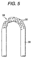
The deterioration process of the filament was examined
as follows. As an example shown in Fig. 5, many voids (air
holes) occur in the interior and surface of the filament 30,
so that the surface is made rugged. When these voids occur and
grow, a distribution in surface temperature of the filament 30
when driving the ion source gradually, becomes non-uniform, and
at the same time, local deterioration of the filament 30
advances thereby, and one portion 34 is made thin. The
non-uniformity in the temperature distribution further
progresses, the portion 34 becomes rapidly thin, and
consequently, the life of the filament 30 is acceleratedly
shortened and goes to breaking of wire.
-
It was seen that when the trimethylindium gas or the
triethylindium gas was used as the raw gas, much merit were
available as mentioned above, but on the other hand, there was
a serious problem that the life of the filament was short.
SUMMARY OF THE INVENTION
-
It is an object of the present invention to enable to
stabilize actuation of the ion source, stabilize the amount of
generating the ion beam, lengthen lives of composing parts and
make maintenance easy.
-
It is another object of the present invention to enable
to lengthen the life of the filament while making the best use
of the merit of employing the trimethylindium gas or the
triethylindium gas as the raw gas.
-
The ion source of the present invention comprising a gas
introducing mechanism for introducing an inert gas and the
organometallic gas into a plasma production container.
-
By the gas introducing mechanism, it is possible to
introduce the inert gas and the organometallic gas being the
raw gas into the plasma production container. As a result, the
flowing amount of the organometallic gas can be lessened while
securing the flowing amount of total gas necessary for
stabilizing and continuing the plasma in the plasma production
container and the amount of the ion beam by the sort of a desired
ion.
-
Consequently, various problems arising in company with
using of the organometallic gas can be reduced, and it is
possible to enable to stabilize the actuation of the ion source,
stabilize the amount of generating the ion beam, lengthen lives
of composing elements and make maintenance easy.
-
Further, in the ion source of the present invention, a
raw gas is trimethylindium gas or the triethylindium gas, and
the filament comprises tantalum.
-
In the above mentioned gases other than the
trimethylindium gas or the triethylindium gas, the rapid
deterioration phenomenon of the wolfram filament was not seen.
Therefore, this is considered as a phenomenon particular to the
combination of the wolfram filament and the trimethylindium gas
or the triethylindium gas.
-
Contemplating the reason therefor, it is assumed that
activated hydrogen or activated carbon are generated by
changing the trimethylindium gas or the triethylindium gas into
plasmas, and they invade between metallic crystals of the
wolfram filament heated at high temperature by their serving
as the hot cathode, whereby many voids appear in the interior
or the surface of the wolfram filament.
-
On the other hand, forming the filament with tantalum (Ta),
it was confirmed that the live was very lengthened in comparison
with wolfram (around 5 to 6 times as later mentioned).
-
Contemplating the reason therefor, it is assumed that the
tantalum filament can occlude the activated hydrogen or the
activated carbon as maintaining the state of metallic crystal.
Therefore, voids are hard to occur in comparison with the
wolfram filament. Tantalum can occlude hydrogen as 740 volume
under e.g., a black-red heat.
BRIEF DESCRIPTION OF THE INVENTION
-
- Fig. 1 is a cross sectional view showing one embodiment
of the ion source according to the present invention;
- Fig. 2 is a cross sectional view partially showing a
circumference of the gas introducing mechanism of the other
example of the ion source according to the invention;
- Fig. 3 is a cross sectional view showing a conventional
ion source;
- Fig. 4 is a cross sectional view showing one embodiment
of the ion source according to the present invention; and
- Fig. 5 is a view schematically showing one example of the
filament, the surface of which is made rugged by occurrence of
voids.
-
PREFERRED EMBODIMENTS OF THE INVNETION
-
Preferred embodiments according to the present invention
will be described as follows referring to the accompanying
drawings.
-
Fig. 1 is a cross sectional view showing one embodiment
of the ion source according to the invention. The same numerals
and signs are given to the same or corresponding parts of the
conventional one shown in Fig. 3, and in the following
description, different regards from the conventional example
will be mainly referred to.
-
This ion source is furnished with two gas introducing
inlets 6 equipped in the wall of the plasma production container
2 as gas introducing mechanisms for introducing an inert gas
32 together with the organometallic gas 28 into the plasma
production container 2, and gas introducing pipes 26 and 30
connected to the respective gas introducing inlets 6 so as to
introduce the organometallic gas 28 and the inert gas 32 via
the respective gas introducing inlets 6 into the plasma
production container 2. This gas introducing mechanisms are,
in brief, for separately introducing the organometallic gas 28
and the inert gas 32.
-
The inert gas 32 is He, Ne, Ar, Kr, Xe or Rn, and they
are also called as rare gases. Mixed gases of two or more kinds
are sufficient. These inert gases 32 are preferable because
even if introducing into the plasma production container 2 at
high temperature, no compound is formed by reacting with
materials composing the filament 8 or the plasma production
container 2 (for example, Ta, W, Mo or Nb).
-
Depending on this ion source, when driving it (that is,
when leading the ion beams 16), it is possible to introduce the
inert gas 32 together with the organometallic gas 28 being the
raw gas into the plasma production container 2 by the gas
introducing mechanism. Namely, the mixed gas of the
organometallic gas 28 and the inert gas 32, in other words, a
gas formed by diluting the inert gas 32 with the organometallic
gas may be used for generating the plasma 12.
-
Consequently, the flowing amount of the organometallic
gas can be lessened while securing the flowing amount of total
gas (that is, total of the organometallic gas 28 and the inert
gas 32) necessary for stabilizing and continuing the plasma 12
in the plasma production container 2 and the amount of the ion
beam by the sort of the desired ion (for example, indium ion).
As a result, the above mentioned various problems arising in
company with using of the organometallic gas can be reduced.
-
This fact will be explained as follows, referring to the
cases that the
organometallic gas 28 is trimethylindium gas and
the
inert gas 32 is an argon gas.
- (1) Since the amount of supplying the trimethylindium gas
can be reduced without spoiling the stable continuation of the
plasma 12, the carbon amount generating by decomposition of
trimethylindium in the plasma production container 2 becomes
reduced. Accordingly, it is possible to reduce lowering of the
insulating capacity of the insulating material 24 between the
filament 8 and the plasma production container 2 or the
insulating material 25 between the reflecting electrode 10 and
the plasma production container 2. Thus, the amount of
generating the plasma 12 and the amount of generating the ion
beam 16 may be stabilized.
- (2) Since the amount of supplying the trimethylindium gas
can be reduced without spoiling the stable continuation of the
plasma 12, the amount of the activated hydrogen or activated
carbon generating by decomposition of trimethylindium in the
plasma production container 2 becomes small. Accordingly, it
is possible to reduce the degree that the filament 8 at high
temperature is hydrogenated or carbonized and effected with
quality alteration. As a result, the amount of generating
thermoelectron from the filament 8 is stable, and the amount
of generating the plasma 12 and the amount of generating the
ion beam 16 may be stabilized. The life of the filament 8 is
also lengthened.
- (3) Since the amounts of the activated hydrogen and
activated carbon generating by decomposition of trimethylindium
becomes small, the degree that the filament 8 is
embrittled is lightened. Thus, the amount of generating
thermoelectron from the filament 8 is stable and the amount of
generating the plasma 12 and the amount of generating the ion
beam 16 may be stabilized. The life of the filament 8 is also
lengthened.
- (4) Since the amount of supplying the trimethylindium gas
can be reduced without spoiling the stable continuation of the
plasma 12, the trimethylindium gas is sufficient with an amount
necessary to obtain a desired amount of the indium ion beam (beam
current). Accordingly, the generation of the excessive indium
or carbon in the plasma production container 2 may be moderated.
As a result, since the contamination is few at the interior of
the plasma production container 2, the actuation of the ion
source can be stabilized. Further, maintenance as cleaning the
interior of the plasma production container 2 can be simplified.
- (5) Since the amount of supplying trimethylindium gas can
be reduced without spoiling the stable continuation of the
plasma 12, the trimethylindium gas more than necessary is not
needed to be supplied. Accordingly, it may be reduced that the
interior of the gas introducing pipe 26 is contaminated and
easily clogged by the indium metal generated by thermal
decomposition of said gas before being supplied into the plasma
production container 2. Therefore, the stable supply of the
trimethylindium gas is possible, and the amount of generating
the ion beam 16 is stabilized.
-
-
Also in the case of the above mentioned organometallic
gases 28 other than the trimethylindium gas, similar effects
may be obtained as (1) to (5).
-
The gas introducing mechanism for introducing the inert
gas 32 together with organometallic gas 28 into the plasma
production container 2 is sufficient with such as an embodiment
shown in Fig. 2. In this embodiment, one gas introducing inlet
6 is provided in the wall of the plasma production container
2, and the two gas introducing pipes 26 and 30 are connected
to the gas introducing inlet 6 via a mixing part 34. This gas
introducing mechanism is, in brief, for previously mixing the
organometallic gas 28 and the inert gas 32 (that is, before the
plasma production container 2) and introducing into the plasma
production container 2.
-
The embodiment of Fig. 2 exhibits similar acting effects
as the example of Fig. 1.
-
If the plasma 12 is generated under the condition that
the inert gas 32 is mixed, although an inert gas ion is contained
in the ion beams 16, there is not any special problem. This
is because the desired ion sort (for example, indium ion) is
ordinarily selected through a mass separator for carrying out
an ion implantation to a target (for example, a substrate).
-
The present invention is not limited to the above
mentioned Bernus type ion source, but may be broadly applied
to other ion sources, for example, electron impact types such
as Kaufmann, Freeman, PIG, or bucket (multi electrode magnetic
field type) types.
-
According to the above embodiments of the present
invention, the ion source is furnished with the gas introducing
mechanism for introducing the inert gas together with the
organometallic gas being the raw gas into the plasma production
container. Accordingly, the flowing amount of the
organometallic gas may be lessened. Further, it is possible
to secure the flowing amount of the total gas necessary for
stabilizing and continuing the plasma in the plasma production
container 2 and the amount of the ion beam by a sort of the desired
ion.
-
Consequently, various problems arising in company with
using the organometallic gas may be moderated. As a result,
it is possible to stabilize actuation of the ion source,
stabilize the amount of generating ion beam, lengthen lives of
composing elements and make maintenance easy.
-
Fig. 4 is a cross sectional view showing one embodiment
according to the invention. The same numerals and signs are
given to the same or corresponding parts of the embodiment shown
in Fig. 1 and the conventional one shown in Fig. 3, and in the
following description, different regards from the conventional
example will be mainly referred to.
-
The filament 108 in this embodiment is composed of
tantalum. As a comparing example, experiments were made on the
filament composed of the conventional wolfram.
-
Into the plasma production container 2, a raw gas 128 is
introduced as the raw gas (source gas) for producing the plasma
12 and the ion beam 16 through a gas introducing inlet 6 and
a gas introducing pipe 26 connected thereto. For the raw gas
128, the trimethylindium gas is employed in this embodiment.
-
In such an ion source, the inside and the outside of the
plasma production container 2 are air-exhausted by vacuum. The
filament 108 is heated by a filament electric source 20 so as
to generate thermoelectron. The raw gas 128 of an appropriate
flowing amount is introduced into the plasma production
container 2. An arc discharging voltage from an arc source 22
is applied between the filament 8 and the plasma production
container 2, so that the arc discharge is generated between the
filament 8 and the plasma production container 2. Then, the
raw gas 128 is ionized to generate the plasma 12. Thus, the
ion beam 16 can be led from this plasma 12.
-
The reflecting electrode 10 repulses electron emitted
from the filament 8 to serve as heightening ionization
efficiency of the gas and generation efficiency of the plasma
12.
-
When comparing lives of the filaments 8 in such an ion
source, the life of the conventionally used wolfram filament
was 1 to several hours, while the life of the tantalum filament
was 30 to 40 hours or longer. Namely, it was confirmed that
if the tantalum filament was employed, the life would be 5 to
6 times of the wolfram filament.
-
The trimethylindium gas used as the raw gas is high in
the steam pressure to a certain extent as mentioned above. Thus,
it is not necessary to use the high temperature oven for
gasification. For example, the gasification can be provided
to a degree of vacuum leading of the container supporting a solid
trimethylindium therein at room temperature. Besides as it has
no deliquescence, the inner wall of the plasma production
container is neither contaminated nor corroded. Accordingly,
a stable operation of the ion source is available, the life of
the ion source is long, and the maintenance such as cleaning
can be simplified.
-
Since the triethylindium gas is an organometallic gas of
the same kind as the trimethylindium gas, similar effects may
be brought about also when the raw gas 28 is the triethylindium
gas.
-
The raw gas 28, that is, the trimethylindium gas or the
triethylindium gas may be introduced as a sole gas into the
plasma production container 2 or together with inert gases (rare
gases) such as Ar, Ne and others. If introducing together with
the inert gas, the flowing amount of the raw gas can be lessened
while securing the flowing amount of total gas (that is, total
of the raw gas 28 and the inert gas 32) necessary for stabilizing
and continuing the plasma 12 in the plasma production container
2 and the amount of the ion beam by the desired indium ion.
Further, it is possible to decrease influences to the filament
8 by the raw gas 28, thereby enabling to lengthen the life of
the filament 8.
-
The present invention is not limited to the above
mentioned Bernus type ion source, but may be broadly applied
to other ion sources having filaments, for example, electron
impact types such as Kaufmann, Freeman, bucket (multi electrode
magnetic field type) types or hot cathode PIG type.
-
According to the invention, it is possible to lengthen
the life of the filament while making the best use of the merit
of employing the trimethylindium gas or the triethylindium gas
as the raw gas, that is, not requiring to use the high temperature
oven, and the merit of neither contaminating nor corroding the
inner wall of the plasma production container with the melted
matters.