EP1073049A2 - Disk drive apparatus - Google Patents
Disk drive apparatus Download PDFInfo
- Publication number
- EP1073049A2 EP1073049A2 EP00306526A EP00306526A EP1073049A2 EP 1073049 A2 EP1073049 A2 EP 1073049A2 EP 00306526 A EP00306526 A EP 00306526A EP 00306526 A EP00306526 A EP 00306526A EP 1073049 A2 EP1073049 A2 EP 1073049A2
- Authority
- EP
- European Patent Office
- Prior art keywords
- disk
- roller
- diameter
- drive apparatus
- disk drive
- Prior art date
- Legal status (The legal status is an assumption and is not a legal conclusion. Google has not performed a legal analysis and makes no representation as to the accuracy of the status listed.)
- Granted
Links
- 238000001514 detection method Methods 0.000 claims description 22
- 238000003780 insertion Methods 0.000 claims description 8
- 230000037431 insertion Effects 0.000 claims description 8
- 230000007246 mechanism Effects 0.000 description 26
- 238000010586 diagram Methods 0.000 description 2
- 230000032258 transport Effects 0.000 description 2
- 238000013459 approach Methods 0.000 description 1
- 238000010276 construction Methods 0.000 description 1
- 230000000994 depressogenic effect Effects 0.000 description 1
- 238000005516 engineering process Methods 0.000 description 1
- 239000002184 metal Substances 0.000 description 1
- 238000012986 modification Methods 0.000 description 1
- 230000004048 modification Effects 0.000 description 1
- 230000002093 peripheral effect Effects 0.000 description 1
- 230000005236 sound signal Effects 0.000 description 1
- 238000011144 upstream manufacturing Methods 0.000 description 1
Images


























Classifications
-
- G—PHYSICS
- G11—INFORMATION STORAGE
- G11B—INFORMATION STORAGE BASED ON RELATIVE MOVEMENT BETWEEN RECORD CARRIER AND TRANSDUCER
- G11B17/00—Guiding record carriers not specifically of filamentary or web form, or of supports therefor
- G11B17/02—Details
- G11B17/04—Feeding or guiding single record carrier to or from transducer unit
- G11B17/05—Feeding or guiding single record carrier to or from transducer unit specially adapted for discs not contained within cartridges
- G11B17/051—Direct insertion, i.e. without external loading means
- G11B17/0515—Direct insertion, i.e. without external loading means adapted for discs of different sizes
-
- G—PHYSICS
- G11—INFORMATION STORAGE
- G11B—INFORMATION STORAGE BASED ON RELATIVE MOVEMENT BETWEEN RECORD CARRIER AND TRANSDUCER
- G11B17/00—Guiding record carriers not specifically of filamentary or web form, or of supports therefor
- G11B17/02—Details
- G11B17/022—Positioning or locking of single discs
- G11B17/028—Positioning or locking of single discs of discs rotating during transducing operation
- G11B17/0282—Positioning or locking of single discs of discs rotating during transducing operation by means provided on the turntable
- G11B17/0283—Two or more turntables
-
- G—PHYSICS
- G11—INFORMATION STORAGE
- G11B—INFORMATION STORAGE BASED ON RELATIVE MOVEMENT BETWEEN RECORD CARRIER AND TRANSDUCER
- G11B17/00—Guiding record carriers not specifically of filamentary or web form, or of supports therefor
- G11B17/02—Details
- G11B17/04—Feeding or guiding single record carrier to or from transducer unit
- G11B17/0401—Details
- G11B17/0402—Servo control
- G11B17/0404—Servo control with parallel drive rollers
-
- G—PHYSICS
- G11—INFORMATION STORAGE
- G11B—INFORMATION STORAGE BASED ON RELATIVE MOVEMENT BETWEEN RECORD CARRIER AND TRANSDUCER
- G11B17/00—Guiding record carriers not specifically of filamentary or web form, or of supports therefor
- G11B17/02—Details
- G11B17/04—Feeding or guiding single record carrier to or from transducer unit
- G11B17/057—Feeding or guiding single record carrier to or from transducer unit specially adapted for handling both discs contained within cartridges and discs not contained within cartridges
Definitions
- the present invention generally relates to a disk drive apparatus, and more particularly to a 1DIN size reproducing apparatus capable of reproducing information from an 8-cm CD (Compact Disk) a 12-cm CD, and an MD (Mini Disk) using a single common head.
- a 1DIN size reproducing apparatus capable of reproducing information from an 8-cm CD (Compact Disk) a 12-cm CD, and an MD (Mini Disk) using a single common head.
- an MD reproducing device and a CD reproducing device each have a roller for loading and a head for reproducing recorded information.
- One way of miniaturizing the apparatus is a head disclosed by Japanese Patent Preliminary Publication No. 10-40512, the head serving to reproduce information either from the MD and CD.
- a CD turntable and an MD turntable are not interchangeable. Therefore, a reproducing apparatus requires turntables specifically designed for reproducing CDs and MDs, respectively.
- the MD turntable and CD turntable require to be spaced apart by a predetermined minimum distance (about 73 mm) over which the common head can move between the MD and CD for reproducing information. This implies that a total width of an area occupied by the CD and MD is at least about 167 mm.
- a 1DIN (German specification) audio size on-vehicle disk drive apparatus has a maximum outer width of less than 178 mm.
- the disk drive apparatus incorporates a roller for loading the MD and CD and associated mechanical components assembled near the roller.
- the roller cannot be longer than 167mm and the CD turntable is required to move to a position directly below the loaded CD such that the CD turntable is accurately centered with respect to the CD.
- the need for moving the turntable has placed a strong demand on the development of a technology in which the same motor can be used both when moving the turntable and when clamping the MD and CD.
- the present invention was made in view of the aforementioned problems.
- An object of the invention is to provide a disk drive apparatus in which a turntable is moved to a location where the turntable is accurately concentric with the disk and then the disk is loaded on the turntable.
- a CD and an MD are selectively loaded into a disk drive apparatus.
- the roller (11) engages the MD and rotates to pull in the MD into the disk drive apparatus when the MD is inserted into one of the upper space and the lower space and engages the CD and rotates to pull in the CD into the disk drive apparatus when the CD is inserted into the other of the upper space and the lower space.
- a first detector (18+20, 19+21) detects the MD and generates a first detection signal when the MD is inserted into the apparatus.
- a second detector (22, 23) detects the CD and generates a second detection signal when the CD is inserted into the apparatus.
- a drive section (171, 172, 173) drives the roller (11) in rotation in directions according to the first detection signal and the second detection signal.
- the roller (11) engages a disk inserted into the disk drive apparatus and is rotated to load the disk in position.
- the roller (11) has a first longitudinal end and a second longitudinal end. The first longitudinal end is supported such that the second longitudinal end is pivotal about the first longitudinal end.
- the roller (11) pivots such that the roller (11) is brought into pressure engagement with the MD or CD.
- a transporting means selectively transports a large-diameter disk (12-cm CD) and a small-diameter disk in a direction of a radius thereof.
- a member (32L, 32R) is pushed by the large-diameter (12-cm CD) disk to rotate when the large-diameter disk (12-cm CD) is transported in the direction of the radius into the apparatus, but is not pushed by the small-diameter disk (8-cm CD) when the small-diameter disk (8-cm CD) is transported in the direction of the radius into the apparatus.
- a stopper (31L, 31R) is operatively connected to the member (32L, 32R).
- the stopper (31L, 31R) causes the large-diameter disk (12-cm CD) to stop such that the large-diameter (12-cm CD) disk is centered at a position when said member (32L, 32R) is rotated by the large-diameter disk (12-cm CD).
- the stopper (31L, 31R) causes the smaller-diameter (8-cm CD) disk to stop such that the smaller-diameter disk (8-cm CD) is centered at the position.
- a switch section generates a detection signal, the detection signal indicating the large-diameter disk when the member (32L, 32R) is pushed by the large-diameter disk and the small-diameter disk when the member (32L, 32R) is not pushed by the small-diameter disk.
- a transporting means selectively transports a 12-cm disk having a 12-cm diameter and a 8-cm disk having an 8-cm diameter in a direction of a radius thereof.
- An 8-cm stopper (32L, 32R) abuts the 8-cm disk to stop the 8-cm disk at a position when the 8-cm disk is inserted into the apparatus, and allows the 12-cm disk to be further transported into the apparatus when the 12-cm disk is inserted into the apparatus.
- a 12-cm stopper (31L, 31R) positions the 12-cm disk after the 8-cm stopper has allowed the 12-cm disk to be further transported such that the 12-cm disk is centered at the position.
- An 8-cm detection switch (36) detects the 8-cm disk when 8-cm disk is inserted into the apparatus.
- a member (34) causes the 8-cm detection switch (36) to become ON when the 8-cm disk has been placed at the position, while preventing the 8-cm detection switch (36) from becoming ON when the 12-cm disk is transported in the direction of the radius into the apparatus.
- FIG. 4 Further another disk drive apparatus has a drum (44) and a turntable (72) that is operatively coupled to the drum.
- the drum (44) rotates through a first predetermined angle to move the turntable to (72) a first position where the turntable (72) is centered with the disk inserted into the apparatus.
- the drum (44) further rotates through a second predetermined angle so that the disk is loaded on the turntable (72).
- the disk drive apparatus includes a first groove (441a) and a second groove (441b) formed in the drum (44).
- the first groove (441a) extends substantially in a circumferential direction and the second groove (441b) extends substantially in a radial direction and communicates with the first groove (441a).
- a plate (45) is pivotally supported and has a shaft (451) that is slidably fitted into the first groove (441a) and the second groove (441b), the plate (45) being driven by the drum to pivot when the shaft (451) is in the second groove (441b) and the drum (44) is rotated.
- a turntable holder (i.e. reproducing section) (70) is pivotally supported and carries the turntable (72) thereon, the turntable holder (70) being pivoted through a third predetermined angle when the shaft (451) is in the second groove (441b) and the drum (44) is rotated.
- a spring (46) engages the turntable holder (70) and the plate (45) and transmits movement of the plate (45) to the turntable holder (70) through an urging force of the spring when the plate (45) pivots.
- the spring (46) urges the plate (45) so that shaft (451) moves out of the second groove (441b) into the first groove (441a).
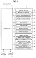
- Fig. 1 is a diagram illustrating a disk drive apparatus.
- a disk drive apparatus includes the following mechanisms: a control circuit 2, a loading mechanism 10 that receives and discharges an MD and a CD, a clamping mechanism 40 that clamps the MD and CD on turntables 71 and 72 (Fig. 3), respectively, and a reproducing section 70 that reads information such as audio signals from the clamped MD and CD.
- the loading mechanism 10 will be described.
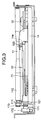
- Fig. 2 is a right side view of the disk drive apparatus illustrating the insertion of a CD and an MD.
- an MD is inserted into a space defined by an MD tray 12 located under a roller 11 while a CD is inserted into a space defined by the roller 11 and a CD guide 13 over the roller 11.
- the roller 11 operates both when the MD is loaded and when the CD is loaded, rotating clockwise or counterclockwise depending on whether a CD is inserted or an MD is inserted.
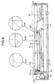
- Fig. 3 is a front view of the disk drive apparatus illustrating a roller and surroundings.
- the roller 11 includes a metal shaft 111 and a rubber roll 112 formed around the shaft 111.
- the rubber roll 112 has a smaller diameter at its mid portion than at its longitudinal end portions. This changing diameter effectively exerts a transporting force on the peripheral portion of the CD to reliably pull in the CD, thereby facilitating insertion of a disk-shaped CD.
- the MD tray 12 is aligned with the left end of the roller 11.
- the MD tray 12 has a left shaft 121 received in a left hole, not shown, of the roller holder 14 and a right shaft 122 received in a right hole 14e.
- the MD tray 12 is pivotal about the hole 14e of the roller holder 14.
- Fig. 4 is a front view of the disk drive apparatus illustrating a roller and surroundings.
- Fig. 5 is a left side view illustrating the insertion of a CD and an MD.
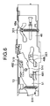
- Fig. 6 is a right side view of the disk apparatus.
- Fig. 7 is a partial left side view of the disk drive apparatus showing the mounting of the roller.
- the roller 11 is rotatably received at its longitudinal end portions in left and right holes formed in a roller holder 14, which in turn is pivotally received in holes 14a.
- the roller 11 also pivots about the holes 14a.
- Springs 15I (Fig. 5) and 15R (Fig. 2) engage left and right ends of the roller holder 14, respectively, to urge the roller holder 14 counterclockwise in Fig. 2 so that the roller 11 is upwardly urged.
- a first link 50 is pivotally supported at holes 50b and has a cut away 50a that receives one end portion of the shaft 111 of the roller 11 therein.
- the first link 50 is urged clockwise by the springs 15L (Fig. 5) and 15R.
- the first link 50 also has a shaft 501 that abuts a second abutting edge 48b of a slide plate 48.
- the second abutting edge 48b prevents the clockwise pivotal movement of the first link 50, thereby maintaining the vertical position of the roller 11 that is urged upwards.
- the second abutting edge 48b of the slide plate 48 defines an elongated hole having a width slightly larger than the diameter of the shaft 501. Therefore, the roller 11 is slightly movable within the elongated hole against the urging forces of the springs 15L and 15R.
- the gap between the CD guide 13 and the mid portion of the roller 11 is 0.5 mm while the gap between the CD guide 13 and the longitudinal end portions of the roller 11 is 0 mm.
- the roller 11 is yieldably depressed downwards by the CD, thereby allowing the CD to enter between the roller 11 and the CD guide 13.
- the roller holder 14 has the left and right holes formed therein that receive the shaft 111 of the roller 11 therein.
- the right hole is substantially circular while the left hole 14b (Fig. 7 and Fig. 15) is an elongated hole describing an arc about the hole 14a.
- the left end portion of the roller 11 is urged downwards by a spring 16, so that the roller 11 is pivotal about the right end of the roller 11, substantially vertically against the urging force of the spring 16.
- the gap between the roller 11 and the MD tray 12 is about 3.5 mm before the MD is inserted.
- the roller 11 is inclined with respect to the MD such that the roller 11 is brought into contact engagement with the MD substantially across the entire width of the MD.
- the roller 11 can apply a transporting force on the left and right ends of the MD, ensuring that the MD is pulled into the apparatus.
- Fig. 9 is a left side view of the disk drive apparatus illustrating a drive mechanism for pulling in the CD and MD.
- a drive mechanism of the roller 11 includes a motor 171, a gear 172 that transmits the rotation of the motor 171 and a belt 173 that transmits the rotation of the gear 172 to the roller 11.
- the drive mechanism drives the roller 11 to rotate clockwise or counterclockwise, depending on whether a CD is loaded or an MD is loaded.
- the roller 11 rotates counterclockwise as seen from the left side of the apparatus when the CD is pulled in, and clockwise when the MD is pulled in.
- the gear 172 is concentric to the hole 14a formed in the roller holder 14 about which the roller 11 pivots. This is advantageous in that when the roller 11 pivots, the tension of the belt 173 remains unchanged. Therefore, the rotation of the gear 172 can reliably be transmitted to the roller.
- Fig. 10 is a top view of the disk drive apparatus just before the CD or MD is inserted into the apparatus.
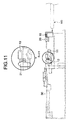
- Fig. 11 is a side view of the disk drive apparatus just before the MD is inserted into the apparatus, showing front and rear switches.
- Fig. 12 is a top view of the disc drive apparatus when the user has inserted the MD to a position where the leading end of the MD is detected.
- a front switch 18 is located at a left side of an entrance of the MD tray 12.
- the MD pushes a lever 20 to shift the front switch 18 from the OFF position to the ON position so that the front switch 18 provides a detection signal to the control circuit 2 (Fig. 12).
- the front switch 18 becomes ON before the MD reaches the roller 11 and remains ON until the MD reaches its loading position (Fig. 19), i.e., when the center of the MD is aligned with the center of the MD turntable 71.
- Fig. 13 is a top view of the disc drive apparatus when the user has inserted the MD to a position just below the roller 11.
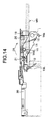
- Fig. 14 is a side view of Fig. 13.
- Fig. 15 is a partial expanded view of Fig. 14.
- the leading end portion of the MD pushes up the roller 11 so that the roller 11 can be in pressure contact with the MD.
- the shaft 111 of the roller 11 is slightly movable within the elongated hole 14b against the urging forces of the spring 16.
- the roller 11 presses the MD downwards and rotates in a direction shown by arrow D3 pulling the MD further into the disk drive apparatus.
- Fig. 16 is a top view of the disc drive apparatus when the MD has been advanced beyond a rear switch 19 from the position of Fig. 15.
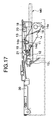
- Fig. 17 is a side view of Fig. 16.
- Fig. 18 illustrates a pertinent portion of Fig. 17.
- Fig. 19 is a top view of the disc drive apparatus when the MD has reached a loading position of MD.
- Fig. 21 is a side view of Fig. 19.
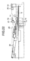
- Fig. 22 is a side view of the disk drive apparatus when the MD is clamped.
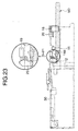
- Fig. 23 is a top view of the disc drive apparatus when the MD has been pulled from the loading position of MD.
- the rear switch 19 is located near the rearward end of the MD tray 12 (Figs. 10 and 11).
- the leading end of the MD pushes the lever 21 (Figs. 16-18) to shift the rear switch 19 from the OFF position to the ON position.
- the MD is further advanced to the loading position shown in Fig. 21 where the clamping member 49 clamps the MD and the rear switch 19 becomes OFF as shown in Fig. 22.
- the rear switch 19 When the clamping member 49 is raised upon the EJECTION command, the rear switch 19 again becomes ON and remains ON until the MD is moved from the loading position to a position (Fig. 23) where the user can pull the MD out of the apparatus.
- a front photosensor 22 is located upstream of the roller 11 with respect to an insertion direction of CD while a rear photosensor 23 is located downstream of the roller 11.
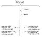
- the front and rear photosensors 22 and 23 each include a light-emitting element and a light-receiving element (Fig. 20B), disposed such that the light-emitting element is over the CD and the light-receiving element is under the CD.
- the front and rear photosensors 22 and 23 provide respective detection signals to the control circuit 2.
- the photosensors 22 and 23 are said to be ON when the inserted CD enters the light path so that the light-receiving element fails to receive the light emitted from the light-emitting element.
- the photosensors 22 and 23 are said to be OFF when the inserted CD exits the light path so that the light-receiving element normally receives the light emitted from the light-emitting element.
- the rear photosensor 23 turns from the ON position to the OFF position when the CD is ejected to a position where the user can pull the CD out of the apparatus.
- Fig. 24 is a top view of the disk drive apparatus, illustrating the CD before it reaches the roller 11.
- Fig. 25 is a side view of the disk drive apparatus, illustrating the CD pulled in by the roller 11 that rotates in a direction shown by arrow D4.
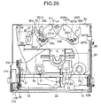
- Fig. 26 is a top view of the disk drive apparatus, illustrating the CD that has just reached the CD detecting lever 34.
- Fig. 27 illustrates a pertinent portion of Fig. 26.
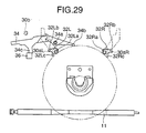
- Fig. 28 illustrates the 8-cm CD when it has been fully inserted into the disk drive apparatus.
- Fig. 29 illustrates the pertinent portion of Fig. 28.
- a pair of 12-cm CD sensing levers 31L and 31R rotatable about holes 31La and 31Ra, respectively.
- the right 12-cm CD sensing lever 31R has a projection 31Rb that pivotally extends into an elongated hole 31Lb of the left 12-cm CD sensing lever 31L, so that the sensing levers 31L and 31R are pivotal with respect to each other.
- the 12-cm CD sensing levers 31L and 31R have locking levers 32L and 32R, respectively, rotatably mounted thereon.
- the locking levers 32L and 32R have holes 32La and 32Ra formed therein, respectively, and are rotatable about the holes 32La and 32Ra.
- the locking lever 32L is biased counterclockwise by a spring 331 and the locking lever 32R is biased clockwise by a spring 33R.
- the subchassis 30 has side portions 30aL and 30aR (Fig. 27) that partially define holes 50c and 50d, respectively, formed in the subchassis 30.
- the urging forces of the springs 31 and 33R cause locking projections 32Lb and 32Rb to be firmly pressed against the side portions 30aL and 30aR (Fig. 27), respectively, so that the 12-cm CD sensing levers 31L and 31R are at their locked positions.
- the 12-cm CD sensing levers 31L and 31R are locked, they are not rotatable.
- the locking projections 32Lb and 32Rb are rotated against the urging forces of the springs 331 and 33R, the 12-cm CD sensing levers 31L and 31R are unlocked.
- the locking lever 32L has a projection 32Lc at the left hand side of the hole 32La and the locking lever 32R has a projection 32Rc at the right hand side of the hole 32Ra.
- the projections 32Lc and 32Rc project towards the roller 11.
- the length of the projections 32Lc and 32Rc are such that they do not abut an 8-cm CD when the 8-cm CD is inserted into the disk drive apparatus but abut a 12-cm CD when the 12-cm CD is inserted.
- the 12-cm CD pushes the projections 32Lc and 32Rc, causing the locking projections 32Lb and 32Rb to move out of pressure engagement with the edge portions 30aL and 30aR (Fig. 27) of the holes 30c and 30d, respectively.
- the 12-cm CD sensing levers 31L and 31R are unlocked so that the 12-cm CD sensing levers 31L and 31R rotate about the holes 31La and 31Ra, allowing the 12-cm CD to advance further into the disk drive apparatus.
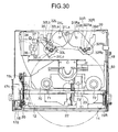
- Fig. 30 is a top view of the disk drive apparatus, illustrating a 12-cm CD that has just reached the projections 32Lc and 32Rc of the locking levers 32L and 32R.
- Fig. 31 illustrates the pertinent portion of Fig. 30.
- a spring 35 has one end fastened to the 12-cm CD sensing lever 31L and the other end fastened to a CD detecting lever 34, thereby biasing the CD detecting lever 34 clockwise.
- the CD detecting lever 34 is rotatable about a hole 34a. The clockwise rotation of the CD detecting lever 34 about the hole 34a is limited by a projection 30b formed on the sub-chassis 30.
- the spring 35 urges the left 12-cm CD sensing lever 31L counterclockwise.
- the CD detecting lever 34 has an upward abutting tip 34b at one end thereof and a pressing portion 34c near an 8-cm CD sensor switch 36.
- the 8-cm CD pushes the abutting tip 34b of the CD detecting lever 34 so that the CD detecting lever 34 rotates counterclockwise about the hole 34a.
- the counterclockwise rotation of the CD detecting lever 34 causes the pressing portion 34c to depress the 8-cm CD sensor switch 36 as shown in Figs. 28 and 29, thereby shifting the 8-cm CD sensor switch 36 from the OFF position to the ON position.
- Fig. 32 illustrates the 12-cm CD sensing levers when they are just unlocked by the 12-cm CD.
- Fig. 33 illustrates the pertinent portion of Fig. 32.
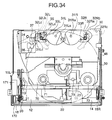
- Fig. 34 is a top view when the 12-cm CD has been fully inserted.
- Fig. 35 illustrates the pertinent portion of Fig. 34.
- Fig. 36 illustrates the 8-cm CD and 12-cm CD when they are being discharged from the disk drive apparatus.
- the 12-cm CD When the 12-cm CD is inserted into the apparatus as shown in Figs. 30 and 31, the 12-cm CD pushes the projections 32Lc and 32Rc, so that the 12-cm CD sensing levers 31L and 31R are unlocked.
- the 12-cm CD then pushes the abutting tip 34b of the CD detecting lever 34 as shown in Figs. 32 and 33, so that the CD detecting lever 34 rotates counterclockwise about the hole 34a but does not push the 8-cm CD sensor switch 36 at all.
- the 12-cm CD sensing lever 31L rotates until a portion 31Lc (Fig. 34) of the 12-cm CD sensing lever 31L pushes the 12-cm CD sensor switch 37, thereby shifting the 12-cm CD sensor switch 37 from the OFF position to the ON position (Figs. 34 and 35)
- the photosensor 23 changes from the ON position to the OFF position when the CD has moved from the loading position to a position where the user can pull the CD out of the apparatus as shown in Fig. 36.
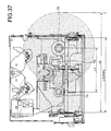
- Fig. 37 illustrates the reason why a CD turntable 72 is required to be angularly moved.
- the MD-turntable 71 and the CD turntable 72 should be spaced apart by a minimum distance L1 (about 73 mm) over which the head 73 is required to move during the reproduction of MD and CD.
- L1 about 73 mm
- L2 about 167 mm
- a disk drive apparatus is a 1DIN audio size reproducing apparatus (German specification) in which a common head is used to read information from both an MD and a CD.
- the 1DIN (178 mm width, 50 mm height) audio size reproducing apparatus should have an entrance of a maximum width of L3 (about 127 mm), through which the MD and CD are inserted into the apparatus.
- L2 is greater than L3. Therefore, in a CD mode, the reproducing section 70 (shown by phantom lines in Fig. 38), which includes the turntables 71 and 72 and head 73, requires to be angularly displaced clockwise about the shaft 74 from the position of Fig. 38 to the position of Fig. 42, and then the CD is clamped to the turntable 72.
- the reproducing section 70 In an MD mode, the reproducing section 70 is not rotated from the position of Fig. 38 and the MD is simply clamped to the reproducing section 70.
- Fig. 38 is a top view illustrating the MD position when the drum 44 has rotated fully counterclockwise.
- Fig. 39 is a right side view of Fig. 38.
- a clamping mechanism 40 includes a motor 42, a gear 43, a drum 44, a rotatable plate 45, and a torsion coil spring 46.
- the control circuit 2 (Fig. 1) controls the motor 42 to drive the gear 43 in rotation, which in turn drives the drum 44 in rotation.
- the drum 44 has a cam groove 441 formed in its upper surface and a cam groove 442 formed in its lower surface.
- the rotatable plate 45 is rotatable about a hole 45a and has a short cam shaft 451 which engages the cam groove 441.
- the rotatable plate 45 also has a first abutting portion 452 and a second abutting portion 453.
- the torsion coil spring 46 has first and second arms 461 and 462 and rotatably fits over the shaft 74.
- the cam groove 441 includes a circumferential groove 441a and a straight groove 441b that communicates with the circumferential groove 441a and extends radially towards the center of the drum 441.
- the rotatable plate 45 When the cam shaft 451 is in the circumferential groove 441a, the rotatable plate 45 will not rotate even if the drum 44 rotates.
- the cam shaft 451 When the cam shaft 451 is in the straight groove 441b, the rotatable plate 45 will be driven to rotate about the shaft 74.
- the wall of the straight groove 441b is substantially perpendicular to a direction in which the cam shaft 451 moves, so that the rotatable plate 45 can be rotated most efficiently by a minimum force.
- the first abutting portion 452 pushes the first arm 461 of the torsion coil spring 46 so that the torsion coil spring 46 rotates clockwise.
- the first arm 461 pushes the reproducing section 70 at a cutout 702 (Fig. 39), thereby causing the reproducing section 70 to rotate clockwise.
- the second abutting portion 453 pushes the second arm 462 of the torsion coil spring 46 so that the torsion coil spring 46 rotates counterclockwise.
- the second arm 462 pushes the reproducing section 70 at a cutout 701, thereby causing the reproducing section 70 to rotate counterclockwise.
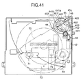
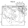
- the reproducing section 70 is rotatable through an angle between an MD mode position (Fig. 41) and a CD mode position (Fig. 42). Due to the resiliency of the torsion coil spring 46, the first and second arms 461 and 462 make three different angles with each other, depending on the rotational positions of the rotatable plate 45. The first and second arms 461 and 462 make larger angles when the rotatable plate 45 rotates beyond the angle range between the MD mode position and CD mode position than when the rotatable plate 45 rotates between the MD mode position and CD mode position. Specifically, as shown in Fig. 43, the first and second arms 461 and 462 make an angle ⁇ when the rotatable plate 45 rotates clockwise beyond the angle range between the MD mode position and CD mode position.
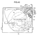
- Fig. 40 illustrates the drum 44 and surroundings when the drum 44 has rotated clockwise through a certain angle from the position of Fig. 38.
- the first and second arms 461 and 462 make an angle ⁇ when the rotatable plate 45 rotates counterclockwise beyond the angle range between the MD mode position and CD mode position. As shown in Figs. 41 and 42, the first and second arms 461 and 462 make an angle ⁇ when the rotatable plate 45 rotates between the MD mode position and the CD mode.
- the angles ⁇ and ⁇ are larger than the angle ⁇ .
- the CD has just been loaded and the shaft 451 of the rotatable plate 45 is in the circumferential groove 441a of the drum 44.
- the reproducing section 70 is at the MD mode position.
- the rotatable plate 45 has been rotated counterclockwise beyond the angle range between the MD mode position and the CD mode position, and the first and second arms 461 and 462 make the angle y.
- the second arm 462 of the torsion coil spring 46 exerts an urging force on the rotatable plate 45 in a direction shown by an arrow D1.
- the rotatable plate 45 remains at the position shown in Fig. 38 since the shaft 451 is pressed by the urging force of the torsion spring 46 against the inner groove wall of the circumferential groove 441a with respect to the center of the drum 44.
- the angular movement of the reproducing section 70 starts from the position shown in Fig. 38.
- the control circuit 2 causes the motor 42 to rotate, thereby driving the drum 44 to rotate clockwise from the position of Fig. 38.
- the shaft 451 moves along the circumferential groove 441a while being urged by the torsion coil spring 46 against the inner groove wall of the circumferential groove 441a with respect to the center of the drum 44.
- the shaft 451 reaches the straight groove 441b, the shaft 451 drops into the straight groove 441b due to the urging force of the torsion coil spring 46.
- the shaft 451 is caught in the straight groove 441b and rotates together with the drum 44, thereby driving the rotatable plate 45 to rotate about the shaft 74 as the drum 44 rotates.
- Fig. 41 is a top view illustrating the reproducing section 70 just before the reproducing section 70 begins to angularly move.
- Fig. 42 is a top view illustrating the reproducing section 70 when it is at the CD mode position.
- Fig. 43 is a top view illustrating the rotatable plate 45 when it has rotated further from the position of Fig. 42.
- the drum 44 rotates clockwise so that the rotatable plate 45 rotates clockwise.
- the first arm 461 and second arm 462 of the torsion coil spring 46 make the angle ⁇ with each other and the reproducing section 70 begins to rotate clockwise about the shaft 74.
- the reproducing section 70 rotates to the CD mode position shown in Fig. 42. After the reproducing section 70 has reached the CD mode position, the reproducing section 70 will not rotate any further.
- the control circuit 2 controls the drum 44 to further rotate, so that the first arm 461 further moves.
- the angle between the first and second arms 461 and 462 changes from ⁇ to ⁇ and the shaft 451 overrides the corner at which the circumferential groove 441a intersects the straight groove 441b, moving out of the straight groove 441b and then entering the circumferential groove 441a (Fig. 43).
- the rotatable plate 45 finally reaches a predetermined position (Fig. 43).
- the first and second arms 461 and 462 of the torsion coil spring 46 make the angle ⁇ so that the first arm 461 exerts a counterclockwise urging force on the rotatable plate 45. Since the urging force of the torsion coil spring 46 presses the shaft 451 of the rotatable plate 45 in a direction shown by arrow D2 against the inner wall of the circumferential groove 441a with respect to the center of the drum 44, the rotatable plate 45 stays where it is.
- the control circuit 2 controls the drum 44 to rotate counterclockwise from the position of Fig. 43.
- a command e.g., EJECTION command
- the control circuit 2 controls the drum 44 to rotate counterclockwise from the position of Fig. 43.
- the shaft 451 moves along the circumferential groove 441a as the drum 44 rotates counterclockwise, while being urged against the inner groove wall of the of the circumferential groove 441a with respect to the center of the drum 44.
- the shaft 451 reaches the straight groove 441b, the shaft 451 drops into the straight groove 441b due to the urging force of the torsion coil spring 46 so that the drum 44 causes the rotatable plate 45 to rotate counterclockwise.
- the control circuit 2 controls the drum 44 to further rotate counterclockwise, thereby angularly displacing the reproducing section 70 from the position of Fig. 42 through the position of Fig. 41 to the position of Fig. 38 (MD mode position).
- the first arm 461 and the second arm 462 make the angle ⁇ so that the torsion coil spring 46 exerts a clockwise urging force on the rotatable plate 45.
- the reproducing section 70 is moved to either the MD mode position or the CD mode position when the shaft 451 is in the straight groove 441b that extends towards the center of the drum 44.
- the above-described construction is efficient since the straight groove 441b extends in a radial direction, substantially perpendicular to a direction in which the drum 44 is rotated.
- the rotatable plate 45 rotates past the MD mode position or the CD mode position of the reproducing section 70, causing the torsion coil spring 46 to apply an urging force to the rotatable plate 45 in a direction opposite to the rotation of the rotatable plate 45.
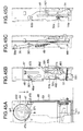
- Figs. 44A-44D illustrate the pertinent mechanism just before the clamping operation, i.e., immediately after the CD has been loaded.
- the clamping mechanism 40 (Fig. 1) further includes a second link 47, a slide plate 48, a subchassis 30, the first link 50, and a shutter 51.
- the second link 47 has a hole 47a at one longitudinal end thereof and is rotatable about the hole 47a.
- the second link 47 has a first shaft 471 provided at an intermediate portion thereof and a second shaft 472 provided at another longitudinal end thereof opposite to the hole 47a.
- the first shaft 471 is loosely fitted into a spiral groove 442 formed in an underside of the drum 44, and the second shaft 472 is pivotally coupled to the slide plate 48.
- the second shaft 472 causes the slide plate 48 to slide in a direction shown by arrow Q or in the direction opposite to the arrow Q, depending on the direction of rotation of the drum 44.
- the slide plate 48 slides towards and away from the entrance in which a CD is inserted into the apparatus.
- the slide plate 48 has a first abutting edge 48a and a second abutting edge 48b (Fig. 44B).
- the subchassis 30 has a hole 30a (Fig. 44C) formed in one end thereof via which the subchassis 30 is rotatably supported, a disk clamping member 49 at the other end, and a shaft 301 between the two opposite ends.
- the shaft 301 abuts the first abutting edge 48a of the slide 48.
- the subchassis 30 is rotatable about the hole 30a so that the disk clamping member 49 substantially moves upwards and downwards.
- the first link 50 has a shaft 501 (Fig.
- the first link 50 is pivotally received in a hole 50b at one end to pivot substantially upwards and downwards about the hole 50b as the slide plate 48 slides back and forth.
- the shutter 51 has a first abutting edge 51a that abuts a first shaft 481 of the slide plate 48 (Fig. 45B) and a second abutting edge 51b that abuts a second shaft 482 of the slide plate 48.
- Fig. 44A illustrates the spiral groove 442 that spirals outwards clockwise as seen from the top.
- the innermost position of the spiral groove 442 is position D where the reproducing section 70 is at the CD mode position.
- the outermost position is position B where the reproducing section 70 is at the MD mode position.
- the shaft 471 moves counterclockwise from the position A through an angle of about 185 degrees, the shaft 471 is at position C immediately before the CD is clamped. From the position B to the position C (about 315 degrees), the spiral groove 442 describes a substantially circular path with the radius varying slightly.
- the cut away defined by the abutting edge 50a of the first link 50 receives the shaft 111 of the roller 11, thereby limiting the vertical position of the roller 11 that is substantially upwardly and downwardly rotatable about the hole 14a of the roller holder 14.
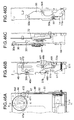
- Figs. 45A-45D illustrate the clamping mechanism when the shaft 471 has moved along the groove 442 from position A of Fig. 44A to position B.
- Figs. 46A-46D illustrate the clamping mechanism when the shaft 471 has moved along the groove 442 from position B of Fig. 45A to position C.
- the second link 47 is at the position A in the spiral groove 442 formed in the drum 44 (Fig. 44A).
- the shaft 301 of the subchassis 30 abuts the highest position of the first abutting edge 48a of the slide plate 48 (Fig. 44B).
- the clamping member 49 has not clamped the MD yet (Fig. 44C).
- the shaft 501 of the first link 50 abuts the highest position of the second abutting edge 48b of the slide plate 48. This is the position where the roller 11 can be in a pressure contact with the MD or CD.
- the second shaft 482 of the slide plate 48 abuts the lower position of the second abutting edge 51b of the shutter 51. This is the position where the gate 511 is at a lower position thereof to allow the user to insert an MD or a CD into the disk drive apparatus.
- the control circuit 2 detects that the MD has been loaded. Then, the control circuit 2 controls the drum 44 to rotate counterclockwise from the position of Fig. 44A, so that the first shaft 471 of the second link 47 moves along the groove 442 from the position A to the position B and the slide plate 48 slides in the direction shown by arrow Q. As a result, as shown in Fig. 45B, the shaft 301 of the subchassis 30 moves to a lower portion of the first abutting edge 48a of the slide plate 48, so that the clamping member 49 of the subchassis 30 clamps the MD (Fig.
- control circuit 2 When the control circuit 2 receives a command (e.g., EJECTION command) which instructs to unclamp the MD, the control circuit 2 controls the drum 44 to rotate clockwise, so that the clamping mechanism 40 returns from the position of Figs. 45A-45D to the position of Figs. 44A-44D.
- a command e.g., EJECTION command
- the control circuit 2 controls the drum 44 to rotate clockwise from the position of Fig. 44A-44D. Then, the first shaft 471 of the second link 47 moves along the spiral groove 442 from the position A through the position C to the position D (Fig. 47A).
- the slide plate 48 remains substantially stationary.
- Figs. 47A-47D illustrate the clamping mechanism when the shaft 471 has moved along the groove 442 from position C of Fig. 46A to position D.
- the first shaft 471 of the second link 47 reaches the position D where the slide plate 48 has slid fully rearwards, i.e., in a direction shown by arrow P.
- the shaft 301 of the subchassis 30 moves to the lower position 48e of the first abutting edge 48a (Fig. 47B).
- the clamping member 49 clamps the CD (Fig. 47C)
- the shaft 501 of the first link 50 moves to the lower position 48c of the second abutting edge 48b where the roller 11 is lowered to move out of engagement with the CD.
- the second shaft 482 of the slide plate 48 moves to the higher position of the second abutting edge 51b of the cover 51, thereby raising the gate 511 to the higher position to prevent the user from inserting an MD or another CD.
- the control circuit 2 Upon receiving a command (e.g., EJECTION command) for instructing to unclamp the CD, the control circuit 2 controls the drum 44 to rotate counterclockwise, so that the clamp mechanism returns from the position of Figs. 47A-47D through the position of Figs. 46A-46D to the position of Figs. 44A-44D.
- a command e.g., EJECTION command
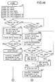
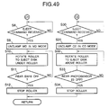
- Figs. 48 and 49 are flowcharts illustrating the major operation of the control circuit 2.
- the front and rear switches 18 and 19 for detecting an MD Prior to the insertion of an MD or a CD, the front and rear switches 18 and 19 for detecting an MD, switches 36 and 37 for detecting a CD (8cm/12cm), and photosensors 22 and 23 for detecting the CD are all in the OFF position at step S1.
- the control circuit 2 monitors the outputs of the front switch 18 and the photosensor 22 to determine at step S2 whether the front switch 18 has turned ON and to determine at step S21 whether the photosensor 22 has become ON.
- the MD pushes the lever 20 to shift the front switch 18 to the ON position at step S2 (YES) and the front switch 18 becomes ON.
- the control circuit 2 determines at step S3 that the apparatus should enter the MD mode, and controls the motor 171 to rotate in a direction (counterclockwise in Fig. 14) in which the MD positioned under the roller 11 is pulled in.
- the gap between the roller 11 and the bottom of the MD tray 12 is slightly narrower than the thickness of the MD.
- the roller 11 is pivotally supported at the right longitudinal end thereof and substantially vertically displaceable at the left longitudinal end thereof against the urging force of a spring 16 (Fig. 7).
- a spring 16 urges the rotating roller 11 to press down the MD with a sufficient force, thereby transporting the MD further into the apparatus.
- the rear switch 19 becomes ON at step S4, the front switch 18 becomes OFF, and the rear switch 19 remains ON at step S5 (YES). If the answer at step S5 is YES, the control circuit 2 determines that the MD has been loaded completely, and then controls the roller 11 to stop at step S6. Then, the control circuit 2 controls the clamping mechanism 40 in the MD mode. In other words, the drum 44 is rotated counterclockwise so that the first shaft 471 of the second link 47 moves from the position A to the position B, thereby clamping the MD (Figs. 22 and 45). As shown in Fig. 22, the rear switch 19 becomes OFF when the MD is clamped.
- control circuit 2 When the control circuit 2 receives (Figs. 22 and 45) an EJECT command at step S8, the control circuit 2 controls the clamping mechanism 40 in the MD mode to unclamp the MD at step S9. The clamping mechanism 40 returns to the condition shown in Fig. 21 and the rear switch 19 becomes ON again.
- the control circuit 2 controls the roller 11 to rotate (Fig. 23) in a direction opposite to that at step S3 until the rear switch 19 becomes OFF.
- the control circuit 2 determines that the apparatus should enter the CD mode and controls the motor 171 to rotate in a direction (clockwise in Fig. 14) in which the CD located on the roller 11 is pulled in (S22)
- the gap between the roller 11 and the CD guide 13 is slightly narrower than the thickness of the CD.
- the roller 11 is supported so that the roller 11 may be pivoted against the urging forces of the springs 15L and 15R. Therefore, when the user inserts the CD into the apparatus with the roller 11 rotating, the roller 11 is lowered against the urging forces of the springs 15I and 15R (Fig. 25).
- the springs 15L and 15R urge the rotating roller 11 to press the CD with a sufficient pressure, thereby pulling the CD further into the apparatus.
- the photosensor 23 becomes ON (S23).
- the 8-cm CD further moves into the apparatus from the position of Figs. 26 and 27 to the position of Figs. 28 and 29, the 8-cm CD pushes the CD detecting lever 34 against the urging force of the spring 35 so that the CD detecting lever 34 rotates counterclockwise.
- the 8-cm CD sensor switch 36 becomes ON at step S24 (YES) so that the control circuit 2 determines that an 8-cm CD has been inserted.
- the control circuit 2 sets the gain of the motor 76 that drives a CD turntable to a value for 8-cm CD at step S25.
- the control circuit 2 also determines that the CD has been loaded, and causes the roller 11 to stop at step S26, and then proceeds to step S27.
- the locking levers 32L and 32R do not rotate when a 8-cm CD is inserted and therefore the 12-cm CD sensing levers 31L and 31R are not unlocked, so that the 8-cm CD is prevented from further moving into the apparatus.
- the photosensor 23 becomes ON (S23).
- the 12-cm CD When the 12-cm CD is advanced from the position of Figs. 26 and 27 to the position of Figs. 28 and 29, the 12-cm CD pushes the locking levers 32L and 32R at the projections 32Lc and 32Rc as shown in Figs. 30 and 31.
- the locking levers 32L and 32R rotate, so that the 12-cm CD sensing levers 31L and 31R are unlocked and rotate as shown in Figs. 32 and 33 and Figs. 34 and 35.
- the CD detecting lever 34 When the 12-cm CD sensing levers 31L and 31R rotate, the CD detecting lever 34 also rotates together with the 12-cm CD sensing lever 31L. Therefore, the CD detecting lever 34 will not push the 8-cm CD sensor switch 36 to the ON position.
- the 12-cm CD sensing levers 31L and 31R When the 12-cm CD sensing levers 31L and 31R have rotated to the positions of Figs. 34 and 35, the 12-cm CD sensing lever 31L pushes the 12-cm CD sensor switch 37 to turn ON at step S28 (YES).
- the control circuit 2 determines that the inserted CD is a 12-cm CD, and sets the motor 76 for the CD turntable to a gain for 12-cm CD at step S29.
- the control circuit 2 also determines that the loading of the CD has been completed, and then stops the roller 11.
- the control circuit 2 controls the clamping mechanism 40 in the CD mode as mentioned previously. That is, as shown in Fig. 43, the control circuit causes the reproducing section 70 to rotate counterclockwise and the turntable for CD 72 to move to the center of the CD inserted. Then, the control circuit 2 causes the CD to be clamped as shown in Fig. 47.
- control circuit 2 Upon receiving an EJECTION command (S30), the control circuit 2 controls the clamping mechanism 40 in the CD mode in order to unclamp the CD (s31). Then, as shown in Fig 36, the control circuit 2 causes the roller 11 to rotate in a direction opposite to that at step S22 until the rear photosensor 23 becomes OFF (S32-S34)
Landscapes
- Feeding And Guiding Record Carriers (AREA)
Abstract
Description
Claims (9)
wherein when the disk is inserted into the disk drive apparatus, said roller (11) pivots such that said roller (11) is brought into pressure engagement with the disk.
Applications Claiming Priority (8)
| Application Number | Priority Date | Filing Date | Title |
|---|---|---|---|
| JP21678499 | 1999-07-30 | ||
| JP11216784A JP2001043596A (en) | 1999-07-30 | 1999-07-30 | Disk drive device |
| JP21678399 | 1999-07-30 | ||
| JP11216783A JP2001043608A (en) | 1999-07-30 | 1999-07-30 | Disk drive device |
| JP24335899A JP3619718B2 (en) | 1999-08-30 | 1999-08-30 | Disk drive device |
| JP24335899 | 1999-08-30 | ||
| JP33450399A JP3796082B2 (en) | 1999-11-25 | 1999-11-25 | Disk drive device |
| JP33450399 | 1999-11-25 |
Publications (3)
| Publication Number | Publication Date |
|---|---|
| EP1073049A2 true EP1073049A2 (en) | 2001-01-31 |
| EP1073049A3 EP1073049A3 (en) | 2002-02-20 |
| EP1073049B1 EP1073049B1 (en) | 2004-10-06 |
Family
ID=27476789
Family Applications (1)
| Application Number | Title | Priority Date | Filing Date |
|---|---|---|---|
| EP20000306526 Expired - Lifetime EP1073049B1 (en) | 1999-07-30 | 2000-07-31 | Disk drive apparatus |
Country Status (2)
| Country | Link |
|---|---|
| EP (1) | EP1073049B1 (en) |
| DE (1) | DE60014533T2 (en) |
Family Cites Families (9)
| Publication number | Priority date | Publication date | Assignee | Title |
|---|---|---|---|---|
| US5481512A (en) * | 1992-06-30 | 1996-01-02 | Victor Company Of Japan, Ltd. | Separable magazine for accommodating discs and a disc player |
| JP3127186B2 (en) * | 1993-10-12 | 2001-01-22 | クラリオン株式会社 | Cartridge loading mechanism |
| JP2882989B2 (en) * | 1993-12-29 | 1999-04-19 | 株式会社ケンウッド | Optical disk recording and playback device |
| JP3895793B2 (en) * | 1996-01-31 | 2007-03-22 | 富士通テン株式会社 | Disk centering mechanism |
| JPH103724A (en) * | 1996-06-12 | 1998-01-06 | Sony Corp | Disc-shaped recording medium holding apparatus and disc-shaped recording medium holding method in disc-shaped recording medium reproducing and / or recording apparatus |
| KR100193619B1 (en) * | 1996-08-26 | 1999-06-15 | 이형도 | Loading aids for automotive compact disc player decks |
| JPH10162466A (en) * | 1996-11-26 | 1998-06-19 | Tanashin Denki Co | Disk reproducing device |
| JP3424227B2 (en) * | 1997-06-04 | 2003-07-07 | 日本ビクター株式会社 | Disc player for both mini and compact discs |
| JP3565248B2 (en) * | 1998-04-17 | 2004-09-15 | パイオニア株式会社 | Disc playback device |
-
2000
- 2000-07-31 EP EP20000306526 patent/EP1073049B1/en not_active Expired - Lifetime
- 2000-07-31 DE DE2000614533 patent/DE60014533T2/en not_active Expired - Fee Related
Also Published As
| Publication number | Publication date |
|---|---|
| EP1073049A3 (en) | 2002-02-20 |
| EP1073049B1 (en) | 2004-10-06 |
| DE60014533T2 (en) | 2005-11-17 |
| DE60014533D1 (en) | 2004-11-11 |
Similar Documents
| Publication | Publication Date | Title |
|---|---|---|
| EP1315161B1 (en) | Disk loading device of recording and reproducing device | |
| US6983471B2 (en) | Disk recording and/or reproducing apparatus | |
| EP0391424A2 (en) | Disk reproducing apparatus | |
| JP3685047B2 (en) | Recording medium mounting device | |
| US20030227856A1 (en) | Disk loading device for disk player and a method for using the same | |
| US8302114B2 (en) | Disk apparatus with carrying unit having arms | |
| US7992157B2 (en) | Disk transportation mechanism and a disk apparatus comprising the same | |
| US5852597A (en) | Recording medium reproducing apparatus accommodating a plurality of recording media and having a reduced height | |
| JP4621372B2 (en) | Disc player | |
| EP1073049B1 (en) | Disk drive apparatus | |
| JPH10162466A (en) | Disk reproducing device | |
| JP3728284B2 (en) | Disk drive device | |
| EP1884945B1 (en) | Loading mechanism and disk playback device using the loading mechanism | |
| JPH07272373A (en) | Disk device | |
| JP3754301B2 (en) | Disk drive device | |
| US20070162919A1 (en) | Disc drive and base unit | |
| JP3877521B2 (en) | Disk drive device | |
| JP3619718B2 (en) | Disk drive device | |
| KR200339946Y1 (en) | Device for distinguishing disk size of disk player | |
| JP3796082B2 (en) | Disk drive device | |
| WO2007108231A1 (en) | Disc player, and method and program for controlling such disc player | |
| JP4207936B2 (en) | Disc loading device | |
| KR100211862B1 (en) | Apparatus for loading a disc of a compact disc player | |
| US20060271943A1 (en) | Recording and reproducing unit and information recording and reproducing device incorporating recording and reproducing unit | |
| JP2003228903A (en) | Disc detection mechanism of disc player |
Legal Events
| Date | Code | Title | Description |
|---|---|---|---|
| PUAI | Public reference made under article 153(3) epc to a published international application that has entered the european phase |
Free format text: ORIGINAL CODE: 0009012 |
|
| AK | Designated contracting states |
Kind code of ref document: A2 Designated state(s): DE FR GB Kind code of ref document: A2 Designated state(s): AT BE CH CY DE DK ES FI FR GB GR IE IT LI LU MC NL PT SE |
|
| AX | Request for extension of the european patent |
Free format text: AL;LT;LV;MK;RO;SI |
|
| PUAL | Search report despatched |
Free format text: ORIGINAL CODE: 0009013 |
|
| AK | Designated contracting states |
Kind code of ref document: A3 Designated state(s): AT BE CH CY DE DK ES FI FR GB GR IE IT LI LU MC NL PT SE |
|
| AX | Request for extension of the european patent |
Free format text: AL;LT;LV;MK;RO;SI |
|
| 17P | Request for examination filed |
Effective date: 20020701 |
|
| AKX | Designation fees paid |
Free format text: DE FR GB |
|
| 17Q | First examination report despatched |
Effective date: 20030325 |
|
| GRAP | Despatch of communication of intention to grant a patent |
Free format text: ORIGINAL CODE: EPIDOSNIGR1 |
|
| GRAS | Grant fee paid |
Free format text: ORIGINAL CODE: EPIDOSNIGR3 |
|
| GRAA | (expected) grant |
Free format text: ORIGINAL CODE: 0009210 |
|
| RAP1 | Party data changed (applicant data changed or rights of an application transferred) |
Owner name: SANYO ELECTRIC CO., LTD. Owner name: TOTTORI SANYO ELECTRIC CO., LTD. |
|
| AK | Designated contracting states |
Kind code of ref document: B1 Designated state(s): DE FR GB |
|
| REG | Reference to a national code |
Ref country code: GB Ref legal event code: FG4D |
|
| REG | Reference to a national code |
Ref country code: IE Ref legal event code: FG4D |
|
| REF | Corresponds to: |
Ref document number: 60014533 Country of ref document: DE Date of ref document: 20041111 Kind code of ref document: P |
|
| ET | Fr: translation filed | ||
| PLBE | No opposition filed within time limit |
Free format text: ORIGINAL CODE: 0009261 |
|
| STAA | Information on the status of an ep patent application or granted ep patent |
Free format text: STATUS: NO OPPOSITION FILED WITHIN TIME LIMIT |
|
| 26N | No opposition filed |
Effective date: 20050707 |
|
| PGFP | Annual fee paid to national office [announced via postgrant information from national office to epo] |
Ref country code: DE Payment date: 20070726 Year of fee payment: 8 |
|
| PGFP | Annual fee paid to national office [announced via postgrant information from national office to epo] |
Ref country code: GB Payment date: 20070725 Year of fee payment: 8 |
|
| PGFP | Annual fee paid to national office [announced via postgrant information from national office to epo] |
Ref country code: FR Payment date: 20070710 Year of fee payment: 8 |
|
| GBPC | Gb: european patent ceased through non-payment of renewal fee |
Effective date: 20080731 |
|
| PG25 | Lapsed in a contracting state [announced via postgrant information from national office to epo] |
Ref country code: DE Free format text: LAPSE BECAUSE OF NON-PAYMENT OF DUE FEES Effective date: 20090203 |
|
| REG | Reference to a national code |
Ref country code: FR Ref legal event code: ST Effective date: 20090331 |
|
| PG25 | Lapsed in a contracting state [announced via postgrant information from national office to epo] |
Ref country code: GB Free format text: LAPSE BECAUSE OF NON-PAYMENT OF DUE FEES Effective date: 20080731 |
|
| PG25 | Lapsed in a contracting state [announced via postgrant information from national office to epo] |
Ref country code: FR Free format text: LAPSE BECAUSE OF NON-PAYMENT OF DUE FEES Effective date: 20080731 |