EP1073024A1 - Commodities delivery device having a pair of gate members and a pair of lock members for enabling a delivery of commodities of various types - Google Patents
Commodities delivery device having a pair of gate members and a pair of lock members for enabling a delivery of commodities of various types Download PDFInfo
- Publication number
- EP1073024A1 EP1073024A1 EP00301113A EP00301113A EP1073024A1 EP 1073024 A1 EP1073024 A1 EP 1073024A1 EP 00301113 A EP00301113 A EP 00301113A EP 00301113 A EP00301113 A EP 00301113A EP 1073024 A1 EP1073024 A1 EP 1073024A1
- Authority
- EP
- European Patent Office
- Prior art keywords
- commodities
- lowermost
- delivery device
- guide path
- members
- Prior art date
- Legal status (The legal status is an assumption and is not a legal conclusion. Google has not performed a legal analysis and makes no representation as to the accuracy of the status listed.)
- Withdrawn
Links
- 125000006850 spacer group Chemical group 0.000 description 5
- WYTGDNHDOZPMIW-RCBQFDQVSA-N alstonine Natural products C1=CC2=C3C=CC=CC3=NC2=C2N1C[C@H]1[C@H](C)OC=C(C(=O)OC)[C@H]1C2 WYTGDNHDOZPMIW-RCBQFDQVSA-N 0.000 description 4
- 230000007246 mechanism Effects 0.000 description 3
- 235000013361 beverage Nutrition 0.000 description 1
- 238000000034 method Methods 0.000 description 1
Images



Classifications
-
- G—PHYSICS
- G07—CHECKING-DEVICES
- G07F—COIN-FREED OR LIKE APPARATUS
- G07F11/00—Coin-freed apparatus for dispensing, or the like, discrete articles
- G07F11/007—Coin-freed apparatus for dispensing, or the like, discrete articles wherein the storage and dispensing mechanism are configurable in relation to the physical or geometrical properties of the articles to be stored or dispensed
-
- G—PHYSICS
- G07—CHECKING-DEVICES
- G07F—COIN-FREED OR LIKE APPARATUS
- G07F11/00—Coin-freed apparatus for dispensing, or the like, discrete articles
- G07F11/02—Coin-freed apparatus for dispensing, or the like, discrete articles from non-movable magazines
- G07F11/04—Coin-freed apparatus for dispensing, or the like, discrete articles from non-movable magazines in which magazines the articles are stored one vertically above the other
- G07F11/16—Delivery means
-
- G—PHYSICS
- G07—CHECKING-DEVICES
- G07F—COIN-FREED OR LIKE APPARATUS
- G07F11/00—Coin-freed apparatus for dispensing, or the like, discrete articles
- G07F11/02—Coin-freed apparatus for dispensing, or the like, discrete articles from non-movable magazines
- G07F11/04—Coin-freed apparatus for dispensing, or the like, discrete articles from non-movable magazines in which magazines the articles are stored one vertically above the other
Definitions
- the present invention relates to a commodities delivery device for delivering commodities stored in a storing section and particularly to a delivery device suitable for use in an automatic vending machine which is for selling canned, bottled, or PET-bottled beverages.
- Each of the commodities delivery devices comprises device frame defining a guide path for guiding commodities downwardly from a storing section, a single gate member cooperated with the device frame for holding a lowermost commodity in the guide path, and a single lock member cooperated with the device frame for holding a second lowermost commodity in the guide path.
- the gate member When the gate member is moved to widen the guide path, the lowermost commodity is delivered through the guide path. During this event, the lock member holds the second lowermost commodity in the guide path. After the gate member is moved to narrow the guide path, the lock member is moved to release the second lowermost commodity. As a result, the second lowermost commodity moves downwardly and is held as the lowermost commodity by the gate member.
- the commodities are delivered from the storing section through the delivery device one by one.
- a previous technique is provided with a width adjusting plate movably placed in the guide pass or a spacer as an additional part detachably mounted.
- a change is required as regards the commodities from one of the types to another of the types, it is necessary to move the width adjusting plate in the guide pass or to change the spacer. This operation takes plenty of time for a setting work for the passageway width.
- the width adjusting needs a complicated mechanism in the delivery device. In a case where the spacer is used, a storing place is necessary for storing the other spacers and further there is a possibility that the spacers may be lost.
- a commodities delivery device for controlling a discharge of commodities stored in a storing section.
- the commodities delivery device comprises a guide path connected to the storing section and extending in upper and lower directions for guiding the commodities downwardly from the storing section, a pair of gate members coupled to the discharge path and cooperated with each other for holding a lowermost one of the commodities in the discharge path, the gate members being opposite to each other in a width direction perpendicular to the upper and lower directions and being movable in the width direction to enable a release of the lowermost one, and a pair of lock members coupled to the discharge path and cooperating to each other for holding a second lowermost one of the commodities in the discharge path at a time when the gate members release the lowermost one, the lock members being opposite to each other in the width direction and movable in the width direction to enable a release of the second lowermost one.
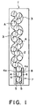
- the serpentine column is designated by a reference numeral 1 and can be used in an automatic vending machine applicable to a plurality of commodity types which are different from one another in a size.
- the serpentine column 1 has a vertically extending commodities passageway 2 configured in a serpentine shape by opposing a number of arc plates 3 to each other.
- the commodities passageway 2 serves as a storing section for storing commodities A or B or C.
- the commodities delivery device is designated by a reference numeral 7 and is placed lower the commodities passageway 2.
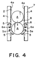
- the commodities delivery device 7 comprises a pair of output device bodies or device frames 4 opposed to each other at the lower end of the commodities passageway 2, a pair of gate levers 5 as first fastening members rotatably arranged in a lower side of respective device frames 4, and a pair of lock levers 6 as second fastening members rotatably arranged in an upper side of respective device frames 4.
- the gate levers 5 and the lock levers 6 are adapted to be rotated by known driving mechanisms made of solenoids which are not shown, respectively.
- the device frames 4 have surfaces 4a which are opposite to each other in a width direction or a horizontal direction to define a guide path 8 having a predetermined width W.
- the guide path 8 is connected to a lower end of the commodities passageway 2 and extends in upper and lower directions or a vertical direction.
- the gate levers 5 are rotatably or pivotally attached to the device frames 4 at their upper ends through shafts 5a so as to operate to protrude their lower ends from the surfaces 4a of the device frames 4 toward the guide path 8 in a delivery standby condition and to retract their lower portions to the inside of the device frames 4 in a commodities delivery condition.
- the lock levers 6 are rotatably or pivotally attached to the device frames 4 at their lower ends through shafts 6a so as to operate to retract their upper portions to the inside of the device frames 4 in the delivery standby condition and to protrude their upper ends from the surfaces 4a of the device frames 4 toward the guide path 8 in the commodities delivery condition.
- each of the commodities A is a largest circular-can of a diameter A1
- each of the commodities B is a smallest circular-can of a diameter B1
- each of the commodities C is a rectangular PET-bottle of a diagonal dimension C1.
- the predetermined width W is determined greater than diameter A1 of the commodity A. Distance L1 between tips of the gate levers 5 and distance L2 between tips of the lock levers 6 in the protruding condition (when the commodity is fastened) are smaller than the diameter B1 of the commodity B. It is to be noted that the width W is greater than the diagonal dimension C1 of commodity C.
- the lowermost commodity A in the guide path 8 is held or fastened by the gate levers 5 in the delivery standby condition and subsequent commodity A is put on the lowermost one.
- the lock levers 6 rotate to the inside of the guide path 8 to hold or fasten the second commodity A from the lowermost one.
- the gate levers 5 rotate to the outside of the guide path 8 to release the lowermost commodity A from the gate levers 5 so as to be dropped downward for being discharged or delivered.
- the gate levers 5 rotate to the inside of the guide path 8.
- the lock levers 6 rotate to the outside of the guide path 8, by which the subsequent commodity A is held or fastened by the lock levers 6 to enter the delivery standby condition.
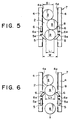
- the lowermost commodity B in the guide path 8 is held or fastened by the gate levers 5 in the delivery standby condition.
- the distance L1 achieved when the gate levers 5 are protruding is shorter than the diameter B1 of the commodity B.
- the distance L2 achieved when the lock levers 6 are protruding is shorter than the diameter B1 of the commodity B, by which the second lowermost commodity B is held or fastened by the lock levers 6 in the commodities delivery condition. Therefore, only the lowermost commodity B is dropped by a rotation of the gate levers 5 so as to be discharged.
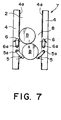
- the gate levers 5 rotate to the inside of the guide path 8 and the lock levers 6 rotate to the outside of the guide path 8. So that, the subsequent commodity B is held or fastened by the lock levers 6 to enter the delivery standby condition.
- the delivered commodity is changed to the commodity C made of the rectangular PET-bottle.
- the guide path 8 is not clogged with the commodity C even if the commodity C is directed with its diagonal direction coincident with the width direction of the guide path 8 since the width W of the guide path 8 between the device frames 4 is longer than the diagonal dimension C1 of the commodity C.
- the width W of the guide path 8 is longer than the diagonal dimension C1 of the commodity C made of a rectangular PET-bottle. Therefore, the guide path 8 is not clogged with the commodity C, so that the commodity C can be reliably prevented from being unsuccessfully output.
Landscapes
- Physics & Mathematics (AREA)
- General Physics & Mathematics (AREA)
- Vending Machines For Individual Products (AREA)
Abstract
In a commodities delivery device having a guide path (8) extends
downwardly from a storing section for storing commodities (A), a pair of gate
members (5) and a pair of lock members (6) are provided to couple with the
guide path. The gate members are opposite to each other in a width direction
of the guide path and cooperated with each other for holding a lowermost
commodity. Each of the gate members is movable in the width direction to
enable a release of the lowermost commodity. The lock members are opposite
to each other in the width direction of the guide path and cooperated with each
other for holding a second lowermost commodity at a time when the gate
members release the lowermost commodity. Each of the lock members is
movable in the width direction to enable a release of the second lowermost
commodity.
Description
- The present invention relates to a commodities delivery device for delivering commodities stored in a storing section and particularly to a delivery device suitable for use in an automatic vending machine which is for selling canned, bottled, or PET-bottled beverages.
- Such commodities delivery devices are disclosed in Japanese Unexamined Patent Publications Nos. 11-45372 and 6-282745. Each of the commodities delivery devices comprises device frame defining a guide path for guiding commodities downwardly from a storing section, a single gate member cooperated with the device frame for holding a lowermost commodity in the guide path, and a single lock member cooperated with the device frame for holding a second lowermost commodity in the guide path. When the gate member is moved to widen the guide path, the lowermost commodity is delivered through the guide path. During this event, the lock member holds the second lowermost commodity in the guide path. After the gate member is moved to narrow the guide path, the lock member is moved to release the second lowermost commodity. As a result, the second lowermost commodity moves downwardly and is held as the lowermost commodity by the gate member. Thus, the commodities are delivered from the storing section through the delivery device one by one.
- In order to enable a delivery of a plurality of types of commodities having different diameters, a previous technique is provided with a width adjusting plate movably placed in the guide pass or a spacer as an additional part detachably mounted. However, when a change is required as regards the commodities from one of the types to another of the types, it is necessary to move the width adjusting plate in the guide pass or to change the spacer. This operation takes plenty of time for a setting work for the passageway width. In addition, the width adjusting needs a complicated mechanism in the delivery device. In a case where the spacer is used, a storing place is necessary for storing the other spacers and further there is a possibility that the spacers may be lost.
- It is an object of the present invention to provide a commodities delivery device in which it is possible to reduce a human labor and to lower a cost in changing the type of commodity from between ones having different external dimensions.
- Other objects of the present invention will become clear as the description proceeds.
- According to the present invention, there is provided a commodities delivery device for controlling a discharge of commodities stored in a storing section. The commodities delivery device comprises a guide path connected to the storing section and extending in upper and lower directions for guiding the commodities downwardly from the storing section, a pair of gate members coupled to the discharge path and cooperated with each other for holding a lowermost one of the commodities in the discharge path, the gate members being opposite to each other in a width direction perpendicular to the upper and lower directions and being movable in the width direction to enable a release of the lowermost one, and a pair of lock members coupled to the discharge path and cooperating to each other for holding a second lowermost one of the commodities in the discharge path at a time when the gate members release the lowermost one, the lock members being opposite to each other in the width direction and movable in the width direction to enable a release of the second lowermost one.
- In The Drawings;
- Fig. 1 is a schematic side view of a serpentine column having a commodities delivery device according to an embodiment of the present invention;
- Fig. 2 is a sectional side view of the commodities delivery device;
- Figs. 3 and 4 are sectional side views for describing an operation of the commodities delivery device of Fig. 2, where relatively large circular-cans are delivered as commodities one by one; and
- Figs. 5-7 are sectional side views for describing an operation of the commodities delivery device of Fig. 2, where relatively small circular-cans are delivered as the commodities one by one; and
- Figs. 8-10 are sectional side views for describing an operation of the commodities delivery device of Fig. 2, where rectangular commodities are delivered one by one.
-
- Referring to Figs. 1-10, description will be made as regards a serpentine column having a commodities delivery device according to an embodiment of the present invention.
- The serpentine column is designated by a reference numeral 1 and can be used in an automatic vending machine applicable to a plurality of commodity types which are different from one another in a size. The serpentine column 1 has a vertically extending
commodities passageway 2 configured in a serpentine shape by opposing a number ofarc plates 3 to each other. Thecommodities passageway 2 serves as a storing section for storing commodities A or B or C. - The commodities delivery device is designated by a
reference numeral 7 and is placed lower thecommodities passageway 2. Thecommodities delivery device 7 comprises a pair of output device bodies ordevice frames 4 opposed to each other at the lower end of thecommodities passageway 2, a pair of gate levers 5 as first fastening members rotatably arranged in a lower side ofrespective device frames 4, and a pair of lock levers 6 as second fastening members rotatably arranged in an upper side ofrespective device frames 4. Thegate levers 5 and thelock levers 6 are adapted to be rotated by known driving mechanisms made of solenoids which are not shown, respectively. - The
device frames 4 havesurfaces 4a which are opposite to each other in a width direction or a horizontal direction to define aguide path 8 having a predetermined width W. Theguide path 8 is connected to a lower end of thecommodities passageway 2 and extends in upper and lower directions or a vertical direction. - The
gate levers 5 are rotatably or pivotally attached to thedevice frames 4 at their upper ends throughshafts 5a so as to operate to protrude their lower ends from thesurfaces 4a of thedevice frames 4 toward theguide path 8 in a delivery standby condition and to retract their lower portions to the inside of thedevice frames 4 in a commodities delivery condition. Thelock levers 6 are rotatably or pivotally attached to thedevice frames 4 at their lower ends throughshafts 6a so as to operate to retract their upper portions to the inside of thedevice frames 4 in the delivery standby condition and to protrude their upper ends from thesurfaces 4a of thedevice frames 4 toward theguide path 8 in the commodities delivery condition. - It is to be noted that each of the commodities A is a largest circular-can of a diameter A1, that each of the commodities B is a smallest circular-can of a diameter B1, and that each of the commodities C is a rectangular PET-bottle of a diagonal dimension C1.
- The predetermined width W is determined greater than diameter A1 of the commodity A. Distance L1 between tips of the
gate levers 5 and distance L2 between tips of the lock levers 6 in the protruding condition (when the commodity is fastened) are smaller than the diameter B1 of the commodity B. It is to be noted that the width W is greater than the diagonal dimension C1 of commodity C. - In the commodities delivery device, as shown in Fig. 2, the lowermost commodity A in the
guide path 8 is held or fastened by the gate levers 5 in the delivery standby condition and subsequent commodity A is put on the lowermost one. In the commodities delivery condition, as shown in Fig. 3, the lock levers 6 rotate to the inside of theguide path 8 to hold or fasten the second commodity A from the lowermost one. After that, the gate levers 5 rotate to the outside of theguide path 8 to release the lowermost commodity A from the gate levers 5 so as to be dropped downward for being discharged or delivered. After that, as shown in Fig. 4, the gate levers 5 rotate to the inside of theguide path 8. After that, the lock levers 6 rotate to the outside of theguide path 8, by which the subsequent commodity A is held or fastened by the lock levers 6 to enter the delivery standby condition. - As shown in Fig. 5, even if the commodity type is changed from the commodity A to the commodity B, the lowermost commodity B in the
guide path 8 is held or fastened by the gate levers 5 in the delivery standby condition. This is because the distance L1 achieved when thegate levers 5 are protruding is shorter than the diameter B1 of the commodity B. In addition, as shown in Fig. 6, the distance L2 achieved when thelock levers 6 are protruding is shorter than the diameter B1 of the commodity B, by which the second lowermost commodity B is held or fastened by the lock levers 6 in the commodities delivery condition. Therefore, only the lowermost commodity B is dropped by a rotation of thegate levers 5 so as to be discharged. After that, as shown in Fig. 7, the gate levers 5 rotate to the inside of theguide path 8 and the lock levers 6 rotate to the outside of theguide path 8. So that, the subsequent commodity B is held or fastened by the lock levers 6 to enter the delivery standby condition. - Furthermore, it will be assumed that, as shown in Fig. 8, the delivered commodity is changed to the commodity C made of the rectangular PET-bottle. In this case, the
guide path 8 is not clogged with the commodity C even if the commodity C is directed with its diagonal direction coincident with the width direction of theguide path 8 since the width W of theguide path 8 between thedevice frames 4 is longer than the diagonal dimension C1 of the commodity C. - Since the distances L1 and L2 achieved when the gate levers 5 and the
lock levers 6 are protruding are shorter than the diameter B1 of the commodity B having the smallest diameter among the commodity types, it becomes possible to secure a permissible range for diameters of the commodities A, B, and C by the protruding lengths of thelevers - Furthermore, the width W of the
guide path 8 is longer than the diagonal dimension C1 of the commodity C made of a rectangular PET-bottle. Therefore, theguide path 8 is not clogged with the commodity C, so that the commodity C can be reliably prevented from being unsuccessfully output. - While the present invention has thus far been described in connection with a few embodiments thereof, it will readily be possible for those skilled in the art to put this invention into practice in various other manners. For example, it is possible to deliver the other commodities each having a size different from that of the above-mentioned commodities with an external dimension of a commodity being greater than the distance between the gate levers and the distance between the lock levers and smaller than the width of the guide path.
Claims (8)
- A commodities delivery device for controlling a discharge of commodities stored in a storing section, said commodities delivery device comprising:a guide path connected to said storing section and extending in upper and lower directions for guiding said commodities downwardly from said storing section;a pair of gate members coupled to said discharge path and cooperated with each other for holding a lowermost one of said commodities in said discharge path, said gate members being opposite to each other in a width direction perpendicular to said upper and lower directions and being movable in said width direction to enable a release of said lowermost one; anda pair of lock members coupled to said discharge path and cooperating to each other for holding a second lowermost one of said commodities in said discharge path at a time when said gate members release said lowermost one, said lock members being opposite to each other in said width direction and movable in said width direction to enable a release of said second lowermost one.
- A commodities delivery device as claimed in claim 1, being applicable to a plurality of commodity types which are different from one another in a size corresponding to said width direction, wherein said gate members have a distance therebetween which is smaller than a smallest one of said commodity types in said size while said gate members hold said lowermost one of the commodities, said lock members having a distance therebetween which is smaller than said smallest one in said size while said lock members hold said lowermost one of the commodities.
- A commodities delivery device as claimed in claim 1, further comprising a device frame having surfaces which are opposite to each other to define said guide path therebetween.
- A commodities delivery device as claimed in claim 3, wherein each of said gate members is a lever having a first and a second end, said first end being pivotally connected to said device frame, said second end being free.
- A commodities delivery device as claimed in claim 4, wherein said second end is placed in said guide path and lower than said first end while said gate members hold said lowermost one of the commodities.
- A commodities delivery device as claimed in claim 3, wherein each of said lock members is a lever having a first and a second end , said first end being pivotally connected to said device frame, said second end being free.
- A commodities delivery device as claimed in claim 6, wherein said second end is placed in said guide path and higher than said first end while said gate members hold said second lowermost one of the commodities.
- A commodities delivery device as claimed in claim 1, wherein each of said commodities is angular in its cross-section and has a diagonal dimension, said guide path having a dimension greater in said width direction than said diagonal dimension.
Applications Claiming Priority (2)
| Application Number | Priority Date | Filing Date | Title |
|---|---|---|---|
| JP21025799 | 1999-07-26 | ||
| JP11210257A JP2001034831A (en) | 1999-07-26 | 1999-07-26 | Vending machine product unloading device |
Publications (1)
| Publication Number | Publication Date |
|---|---|
| EP1073024A1 true EP1073024A1 (en) | 2001-01-31 |
Family
ID=16586399
Family Applications (1)
| Application Number | Title | Priority Date | Filing Date |
|---|---|---|---|
| EP00301113A Withdrawn EP1073024A1 (en) | 1999-07-26 | 2000-02-14 | Commodities delivery device having a pair of gate members and a pair of lock members for enabling a delivery of commodities of various types |
Country Status (2)
| Country | Link |
|---|---|
| EP (1) | EP1073024A1 (en) |
| JP (1) | JP2001034831A (en) |
Families Citing this family (1)
| Publication number | Priority date | Publication date | Assignee | Title |
|---|---|---|---|---|
| JP6447025B2 (en) * | 2014-11-07 | 2019-01-09 | 富士電機株式会社 | Vending machine product unloading device |
Citations (6)
| Publication number | Priority date | Publication date | Assignee | Title |
|---|---|---|---|---|
| FR1524751A (en) * | 1967-05-29 | 1968-05-10 | Scheidt & Bachmann G M B H | Coin collecting device for vending machines |
| US3837528A (en) * | 1970-07-06 | 1974-09-24 | Kinematics & Controls Corp | Article delivery systems for vending machines having sequentially actuated dispensers |
| EP0067242A1 (en) * | 1981-06-17 | 1982-12-22 | Fuji Electric Co., Ltd. | Goods storage and discharge system of an automatic vending machine |
| EP0343505A2 (en) * | 1988-05-26 | 1989-11-29 | Horst Honebein | Article magazine |
| JPH06282745A (en) | 1993-03-26 | 1994-10-07 | Sanden Corp | Article delivery device for automatic vending machine |
| JPH1145372A (en) | 1997-07-28 | 1999-02-16 | Sanyo Electric Co Ltd | vending machine |
-
1999
- 1999-07-26 JP JP11210257A patent/JP2001034831A/en active Pending
-
2000
- 2000-02-14 EP EP00301113A patent/EP1073024A1/en not_active Withdrawn
Patent Citations (6)
| Publication number | Priority date | Publication date | Assignee | Title |
|---|---|---|---|---|
| FR1524751A (en) * | 1967-05-29 | 1968-05-10 | Scheidt & Bachmann G M B H | Coin collecting device for vending machines |
| US3837528A (en) * | 1970-07-06 | 1974-09-24 | Kinematics & Controls Corp | Article delivery systems for vending machines having sequentially actuated dispensers |
| EP0067242A1 (en) * | 1981-06-17 | 1982-12-22 | Fuji Electric Co., Ltd. | Goods storage and discharge system of an automatic vending machine |
| EP0343505A2 (en) * | 1988-05-26 | 1989-11-29 | Horst Honebein | Article magazine |
| JPH06282745A (en) | 1993-03-26 | 1994-10-07 | Sanden Corp | Article delivery device for automatic vending machine |
| JPH1145372A (en) | 1997-07-28 | 1999-02-16 | Sanyo Electric Co Ltd | vending machine |
Also Published As
| Publication number | Publication date |
|---|---|
| JP2001034831A (en) | 2001-02-09 |
Similar Documents
| Publication | Publication Date | Title |
|---|---|---|
| CN103426229B (en) | Paper sheet conveying device and paper processing apparatus | |
| EP2512964B1 (en) | Device for handling banknotes | |
| ITMI991601A1 (en) | AUTOMATIC BOTTLE DISPENSER | |
| KR102265157B1 (en) | Commodity delivering apparatus of vending machine | |
| CH672690A5 (en) | ||
| US6059651A (en) | Apparatus for lifting circular plate bodies | |
| KR20110055336A (en) | Coin hopper with push-up passage | |
| EP0645742B1 (en) | Cash desk, the safe of which is selectively operable by two cashiers | |
| KR102138791B1 (en) | Coin issuing device | |
| DE69815487T2 (en) | Improvements to a cash dispenser | |
| JP5134941B2 (en) | Sheet stacking structure of dispensing device | |
| JPH01197260A (en) | Feed mechanism for printer | |
| DE69119950T2 (en) | Single-channel device for checking, storing and collecting coins | |
| GB2224498A (en) | Mechanism for dispensing article from stack | |
| DE3431779A1 (en) | BANKNOTE DISPENSER | |
| EP0401945A1 (en) | Storage and delivery device for coins | |
| JP4101093B2 (en) | Vending machine product storage device | |
| EP0229264A2 (en) | Dispensing assembly for a vending machine | |
| JPS647426Y2 (en) | ||
| WO2000023352A1 (en) | Tablet dispenser | |
| GB2524468A (en) | Vend mechanism | |
| JP4312161B2 (en) | vending machine | |
| JP2001034831A (en) | Vending machine product unloading device | |
| US3358700A (en) | Coin handling apparatus | |
| JPH10320592A (en) | Aligned ticketing device |
Legal Events
| Date | Code | Title | Description |
|---|---|---|---|
| PUAI | Public reference made under article 153(3) epc to a published international application that has entered the european phase |
Free format text: ORIGINAL CODE: 0009012 |
|
| AK | Designated contracting states |
Kind code of ref document: A1 Designated state(s): DE ES FR GB IT |
|
| AX | Request for extension of the european patent |
Free format text: AL;LT;LV;MK;RO;SI |
|
| 17P | Request for examination filed |
Effective date: 20010723 |
|
| AKX | Designation fees paid |
Free format text: DE ES FR GB IT |
|
| STAA | Information on the status of an ep patent application or granted ep patent |
Free format text: STATUS: THE APPLICATION HAS BEEN WITHDRAWN |
|
| 18W | Application withdrawn |
Withdrawal date: 20021108 |