EP1072545A2 - Sheet feeding apparatus, image reading apparatus and image forming apparatus - Google Patents
Sheet feeding apparatus, image reading apparatus and image forming apparatus Download PDFInfo
- Publication number
- EP1072545A2 EP1072545A2 EP00116336A EP00116336A EP1072545A2 EP 1072545 A2 EP1072545 A2 EP 1072545A2 EP 00116336 A EP00116336 A EP 00116336A EP 00116336 A EP00116336 A EP 00116336A EP 1072545 A2 EP1072545 A2 EP 1072545A2
- Authority
- EP
- European Patent Office
- Prior art keywords
- pressure
- sheet feeding
- pressure contact
- sheets
- pressure releasing
- Prior art date
- Legal status (The legal status is an assumption and is not a legal conclusion. Google has not performed a legal analysis and makes no representation as to the accuracy of the status listed.)
- Granted
Links
- 238000000926 separation method Methods 0.000 claims description 65
- 230000001105 regulatory effect Effects 0.000 claims description 17
- 230000000694 effects Effects 0.000 claims description 3
- 238000011144 upstream manufacturing Methods 0.000 claims description 2
- 230000000452 restraining effect Effects 0.000 claims 3
- 238000010276 construction Methods 0.000 description 21
- 238000000034 method Methods 0.000 description 2
- 230000015572 biosynthetic process Effects 0.000 description 1
- 238000004140 cleaning Methods 0.000 description 1
- 230000006835 compression Effects 0.000 description 1
- 238000007906 compression Methods 0.000 description 1
- 230000002093 peripheral effect Effects 0.000 description 1
Images






Classifications
-
- B—PERFORMING OPERATIONS; TRANSPORTING
- B65—CONVEYING; PACKING; STORING; HANDLING THIN OR FILAMENTARY MATERIAL
- B65H—HANDLING THIN OR FILAMENTARY MATERIAL, e.g. SHEETS, WEBS, CABLES
- B65H3/00—Separating articles from piles
- B65H3/46—Supplementary devices or measures to assist separation or prevent double feed
- B65H3/52—Friction retainers acting on under or rear side of article being separated
- B65H3/5246—Driven retainers, i.e. the motion thereof being provided by a dedicated drive
-
- B—PERFORMING OPERATIONS; TRANSPORTING
- B65—CONVEYING; PACKING; STORING; HANDLING THIN OR FILAMENTARY MATERIAL
- B65H—HANDLING THIN OR FILAMENTARY MATERIAL, e.g. SHEETS, WEBS, CABLES
- B65H3/00—Separating articles from piles
- B65H3/02—Separating articles from piles using friction forces between articles and separator
- B65H3/06—Rollers or like rotary separators
- B65H3/0669—Driving devices therefor
Definitions
- This invention relates to a sheet feeding apparatus for feeding sheets one by one, and more particularly to a sheet feeding apparatus for use in an image forming apparatus such as a copier, a facsimile apparatus, a printer or a scanner.
- a separation feed portion for sequentially feeding originals one by one to an image reading portion for reading images is of a construction in which the release of the pressure contact of a separation pad brought into pressure contact with a separation roller for feeding originals on a stocking plate and separating the originals is possible, and is designed such that the pressure contact of the separation pad is not released in the case of plural-sheets feeding in which a plurality of originals are set and fed one by one, and the pressure contact of the separation pad can be released in the case of one-sheet feeding in which an original is set and fed.
- the pressure contact of this separation pad and the release of the pressure contact are designed to be manually effected.
- the present invention has been made in view of the above-noted situation, and the typical construction of the present invention for achieving the above object is a sheet feeding apparatus having a stocking plate on which a plurality of sheets are stackable, separating means for separating the sheets stacked on the stocking plate one by one by a pair of pressure contact members, feeding means for feeding the sheets, and pressure releasing means for releasing the pressure contact of the pair of pressure contact members, and having returning means for acting on the pressure releasing means to thereby return the pair of pressure contact members to their pressure contact state after the feeding of a sheet has been terminated when the sheets are fed with the pair of pressure contact members released from their pressure by the pressure releasing means.
- a sheet feeding apparatus and an image forming apparatus according to a first embodiment will hereinafter be described in detail with reference to the drawings.
- a facsimile apparatus is exemplified as the image forming apparatus
- an original conveying portion in the image reading portion of the facsimile apparatus is exemplified as the sheet feeding apparatus to which the present invention is applied.
- Fig. 12 is a typical cross-sectional view schematically showing the construction of the facsimile apparatus according to the present embodiment.
- the reference numeral 1 designates the main body of the apparatus which is comprised of an image reading portion 2 for reading the images of originals S as sheets to be read, and an image recording portion 10 for recording the images on recording sheets P as sheets such as recording paper.
- the image reading portion 2 has an upper surface cover 8 having an original stocking plate 8a on which a plurality of originals S are stackable, a close contact type image sensor 4 as reading means for reading the images of the originals S, original urging means 5 for urging the originals S against the close contact type image sensor 4, an original conveying portion for sequentially feeding the originals S stacked on the original stocking plate 8a one by one and conveying the originals S through the close contact type image sensor 4, and an upper original guide 6 and a lower original guide 7 forming the conveyance path of the originals S.
- the upper surface cover 8 having the original stocking plate 8a is openably-closably mounted to the main body 1 of the apparatus so that the interchange of a cartridge and the clearance of jamming which will be described later can be done easily. Also, a slider 8b slidable in a widthwise direction orthogonal to the conveyance direction of the originals S is provided on the original stocking plate 8a, and the opposite ends of the originals S stacked on the original stocking plate 8a can be jogged by this slider 8b.
- the close contact type image sensor 4 as the reading means applies light from an LED array as a light source to the image information surface of the original S, and images the reflected light (image light) reflected by the image information surface on a sensor element by a SELFOC lens (registered trademark), thereby reading the image information.
- SELFOC lens registered trademark
- the original conveying portion 3 as the sheet feeding apparatus to which the present invention is applied will be described later in detail.
- the image recording portion 10 has a recording sheet stacking portion 23 stacking thereon recording sheets P as sheets for recording, a recording sheet feeding portion 12 for sequentially feeding the recording sheets P one by one from the recording sheet stacking portion 23, an image forming portion 11 for recording and forming the images on the fed recording sheets P, a laser scanner 13 for applying a laser beam (image light) as image information to the image forming portion 11, a common use discharge tray 19 for stacking and holding thereon the originals S discharged after the completion of reading and the recording sheets P discharged after the completion of recording, a recording sheet discharge plate 18 for stacking and holding thereon the recording sheets P U-turn-discharged after the recording, and a conveying guide 17 for guiding and supporting the conveyed recording sheets P.
- a laser scanner 13 for applying a laser beam (image light) as image information to the image forming portion 11
- a common use discharge tray 19 for stacking and holding thereon the originals S discharged after the completion of reading and the recording sheets P discharged after the completion of recording
- the recording sheet feeding portion 12 is such that when feeding is started, the recording sheets P brought into pressure contact with the separation roller 12b are separated one by one by this separation roller 12b and a separation pad 12a in pressure contact therewith, whereafter the recording sheet P is conveyed between the photosensitive drum 11a and transferring means 11f of the image forming portion 11 by a conveying roller 12c and a conveying runner 12d urged against it and rotated by it, in timed relationship so that the leading end of an image (toner image) formed by the image forming portion 11 and the leading end of the recording sheet P may be registered with each other.
- a slider 21 slidable in the widthwise direction orthogonal to the conveyance direction of the recording sheets P is provided on the recording sheet stacking portion 23, and the opposite ends of the recording sheets P stacked on the recording sheet stacking portion 23 can be jogged by this slider 21.
- the recording sheet stacking portion 23 can stack a plurality of recording sheets P thereon, and in the present embodiment, the number of recording sheets which can be set thereon is about 100 sheets. Further, the sizes of the recording sheets which can be stacked and set on the recording sheet stacking portion 23 are three sizes, i.e., A4 size, letter size and legal size.
- the number of recording sheets which can be set and the sizes of the recording sheets which can be stacked and set are not limited to those mentioned above, but a suitable construction can be adopted as required.
- a laser beam which is an image signal is first emitted from the laser beam emitter 13a of the laser scanner 13 on the basis of the image signal.
- This laser beam is applied to the photosensitive drum 11a of the image forming portion 11 by a polygon mirror 13b and a turn-back mirror 13c, and an image is formed on the surface of the photosensitive drum 11a.
- the photosensitive drum 11a is incorporated in a frame with charging means 11b, developing means 11c and cleaning means 11d as process means acting thereon to thereby constitute a process cartridge 11e, which is detachably mountable to the main body 1 of the apparatus. Accordingly, during the aforedescribed image formation, the laser beam may be applied from the laser scanner 13 to the surface of the photosensitive drum 11a uniformly charged by the charging means 11b, whereby a latent image is formed thereon, and this latent image may be made into a visible image (toner image) by a toner supplied from the developing means 11c.
- the transferring means 11f for transferring the toner image formed on the surface of the drum to the recording sheet P is disposed on the peripheral portion of the photosensitive drum 11a, and fixing means 14 for fixing the transferred toner image on the recording sheet P is disposed in the recording sheet conveyance path downstream of the photosensitive drum 11a.
- the reference numerals 15 and 16 designate pairs of discharge rollers.
- the recording sheet P fed from the recording sheet stacking portion 23 in timed relationship with the image forming portion 11 may be conveyed to the fixing means 14 along a conveying guide 17 after the toner image formed on the surface of the photosensitive drum 11a has been transferred thereto by the transferring means 11f, and may have the toner image thereon fixed by the fixing means 14, and may be discharged to the common use discharge tray 19 by the pair of discharge rollers 15 or to a recording sheet discharge plate 18 by the pair of discharge rollers 16 through a U-turn path.
- the upper surface cover 8 having the original stocking plate 8a can be opened to thereby easily clear of the recording sheet P stagnating in the interior of the apparatus.
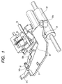
- FIGS. 1, 2A and 2B are perspective views of the essential portions of the original conveying portion in the image reading portion
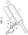
- Fig. 3 is a perspective view showing the construction of a stopper portion in the original conveying portion
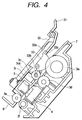
- Figs. 4 to 6 show the constructions of the essential portions of the original conveying portion in the image reading portion
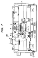
- Figs. 7 and 8 are top plan views of an upper original guide unit.
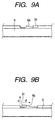
- Figs. 9A and 9B show the constructions of the essential portions of the changeover portion of a pressure releasing lever in the original conveying portion
- Fig. 10 is a cross-sectional view showing the pressure contact state of a separating portion
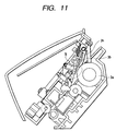
- Fig. 11 is a cross-sectional view showing the pressure contact released state of the separating portion.
- the reference numeral 31 designates a pressure releasing lever which is pressure releasing means for a separation pad 3b, and it is for releasing the pressure contact of the separation pad 3b which is in pressure contact with a separation roller 3a.
- the separation roller 3a and the separation pad 3b together constitute a pair of pressure contact member, and the separating operation is performed by the action of these members.
- a pressure releasing lever 31 is pivotally movable about the center of rotation 31b.
- an initializing lever 32 as a lever member pivotally movable in operative association with the changeover of regulating means which will be described later is mounted on the pressure releasing lever 31 for rotation about the center of rotation 32b.
- the reference numeral 33 denotes a stopper as regulating means, and it is for regulating the leading ends of the originals S placed on the stocking plate 8a.
- the reference character 3c designates a feed runner, and the reference character 3d denotes a feed roller, and these rollers together constitute feeding means.
- the reference numeral 3h designates a preliminary pressure contact arm disposed so as to abut against the separation roller 3a on the widthwisely opposite sides of the separation pad 3b and on the upstream side with respect to the sheet conveyance direction.
- the reference character 3j denotes a separation pad holder for holding the separation pad 3b, and it is movable with the separation pad 3b.
- the position shown in Fig. 7 is the initial position of the pressure releasing lever 31, i.e., the position when the separation pad 3b is in pressure contact.
- a user holds an operating portion 31c and moves the pressure releasing lever 31 in the direction indicated by the arrow a in Fig. 7, there is brought about a state as shown in Fig. 8, i.e., a state in which the pressure contact of the separation pad 3b which is in pressure contact with the separation roller 3a has been released.
- the pressure releasing lever 31 receives a force with which it is returned in the direction indicated by the arrow d in Fig. 8 by a spring 34.
- a tension spring is used as the spring 34, this is not restrictive, but of course, for example, a compression spring, a leaf spring or the like may also be used.
- Figs. 9A and 9B which are views looking in the directions of arrows IXA and IXB in Figs. 7 and 8, the state shown in Fig. 9A is the initial position of the pressure releasing lever 31 which is a state in which the separation pad 3b is in pressure contact, and the state shown in Fig. 9B is a state in which the pressure contact of the separation pad 3b has been released.
- the pressure releasing lever 31 moved to a pressure-releasing position, as shown in Fig. 9B is restrained by a projected portion 6a provided on the upper original guide 6, and is locked in the pressure-releasing position against the force of restitution of the spring 34.
- the pressure releasing lever 31 receives a force in the direction indicated by the arrow e in Fig. 9B by the initializing lever 32, the pressure releasing lever 31 may become disengaged from the projected portion 6a of the upper original guide 6 and be returned in the direction indicated by the arrow d in Fig. 9B by the force of restitution of the spring 34.
- Fig. 3 briefly describe the movement of the stopper 33 which is regulating means for regulating the leading end of the original to a regulating position and a regulation releasing position and the operation of returning it to an initial state (initializing operation).
- the initializing operation of the stopper 33 is the operation of lowering the stopper 33 by utilizing the reversely rotating operation of a driving motor for the feed roller 3d after the completion of the conveyance of the original, and making the stopper 33 wait in its lowered state.
- the construction is such that when the driving motor is rotated in a direction opposite to the direction indicated by the arrows (conveyance direction) as shown in Fig. 3, the projection (liberating source) 3ca of the feed runner 3c abuts against and is regulated by the lower portion of the projection 33b of the stopper 33, and the feed roller 3d and the feed runner 3c slide to thereby return the stopper 33 to its initial state (regulating position) which is the lowered state.
- the movement of the stopper 33 to the regulation releasing position is such that the feed roller 3d rotates in the original conveying direction and the feed runner 3c with the liberating source 3ca is rotated therewith, and the projection 3ca of this feed runner 3c abuts against the upper portion of the projection 33b of the stopper 33 and in accordance therewith, the stopper 33 rotates about a shaft 33a in the direction indicated by the arrow (Fig. 3) and upwardly retracts (releases the regulation).
- the automatic initializing operation from the pressure-released state of the separation pad 3b is performed by the use of the changeover operation of this stopper 33.
- Fig. 4 shows the state of the stopper 33 during the pressure release of the separation pad 3b shown in Figs. 8 and 11.
- the feed roller 3d begins to be rotated in the direction indicated by the arrow and therewith, the feed runner 3c with the liberating source is rotated in the direction indicated by the arrow, and the stopper 33 rotates in the direction indicated by the arrow f.
- the distal end of the stopper 33 rotates and rises in the direction indicated by the arrow g to thereby raise the arm portion 32a of the initializing lever 32, and as shown in Fig. 6, the up-down relation between the arm portion 33c of the stopper 33 and the arm portion 32a of the initializing lever 32 is reversed.
- the pressure releasing lever 31 When this push-up of the pressure releasing lever 31 exceeds the projected portion 6a shown in Fig. 9B, the pressure releasing lever 31 may be returned in the direction indicated by the arrow d in Fig. 9B by the force of restitution of the spring 34.
- the initialization (return to the initial position) of the pressure releasing lever 31 for the separation pad 3b can be accomplished by a very simple and low-cost construction. Thereby, forgetting to return the separation pad 3b to its pressure contact position after one-sheet feeding of the original S effected with the pressure contact of the separation pad 3b released by the pressure releasing lever 31 has been terminated can be prevented, and an inconvenience such as the bad conveyance of the originals S caused by this forgetting to return can be prevented, and the usability and quality of the apparatus are markedly improved.
- the pressure releasing lever 31 is restrained and fixed by the projected portion 6a when it has moved the separation pad 3b to the pressure-released position, and is automatically returned to its original position (initial position) by the force of restitution of the spring 34 when this restraint is released and therefore, the automatic return of the pressure releasing lever 31 can be accomplished simply and at a low cost. Also, the pressure releasing lever 31 scarcely receives the force of the spring 34 in the waiting position (the pressure contact position of the separation pad 3b) which is the original position and therefore, there is no possibility of creep deformation or the like.
- the restraint of the pressure releasing lever 31 is released through the initializing lever 32 pivotally moved in operative association with the changeover of the stopper 33, whereby the separation pad 3b is automatically returned to its pressure contact position, that is, the pressure releasing lever 31 is automatically returned to its original position (initial position) by the use of the principle of the lever, and therefore, a great force can be generated by small power and be used as motive power for automatic return.
- the operating portion 31c of the pressure releasing lever 31 is moved to the right and left as shown in Figs. 7 and 8, whereby plural-sheets feeding or one-sheet feeding is selected.
- the originals S are set on the original stocking plate 8a.
- the originals S are nipped between the separation roller 3a and the preliminary pressure contact arm 3h which is in pressure contact with the separation roller 3a.
- the leading ends of the originals S strike against the stop surface of the stopper 33 which is in its initial state (regulating position) and cannot go in any further.
- the stopper 33 is liberated by the feed runner 3c with the liberating source, and the originals S are fed to the separation pad 3b portion by the separation roller 3a with which the preliminary pressure contact arm 3h is in pressure contact.
- the originals S are then separated and fed one by one by the separation roller 3a and the separation pad 3b which is in pressure contact with the separation roller 3a.
- the pressure contact between the separation roller 3a and the separation pad 3b is released in advance, and the stopper 33 is liberated by the feed runner 3c with the liberating source, and the original S is fed by the separation roller 3a with which the preliminary pressure contact arm 3h is in pressure contact, and arrives at the feed roller 3d portion.
- the originals S are further conveyed to the close contact type image sensor 4 by the feed roller 3d which is in pressure contact with the feed runner 3c urged by the urging spring 31, and the image information of the originals S is read while the originals S are sequentially line-fed while being urged into close contact with the close contact type image sensor 4 by the original urging means 5. Thereafter, the originals S may be discharged to the common use discharge tray 19 by a discharge roller 3f which is in pressure contact with a discharge runner 3e urged by the urging spring 3i. In the meantime, the originals S are guided by the upper original guide 6 and the lower original guide 7.
- the reversely rotating operation is performed and the stopper 33 is initialized, and in the case of one-sheet feeding, the initialization of the pressure releasing lever 31 for the separation pad 3b is also effected together.
- design is made such that the changeover of the stopper 33 to the regulating position and the regulation releasing position is effected by the forward and reverse rotations of the feed runner 3c with the liberating source, and design is also made such that the separation pad 3b is moved to the pressure-released position by the pressure releasing lever 31, and after the feeding of an original has been terminated, the pressure releasing lever 31 is automatically returned to its initial position (the pressure contact position of the separation pad 3b) which is the original position in operative association with the changeover of the stopper 33 in order to return the separation pad 3b to its pressure contact position and therefore, forgetting to return the separation pad 3b to its pressure contact position after one-sheet feeding of the original S effected in the pressure-released state of the separation pad 3b by the pressure releasing lever 31 has been terminated can be prevented, and an inconvenience such as the bad conveyance of the originals caused by the forgetting to return can be prevented, and the usability and quality of the apparatus are markedly improved.
- the present invention is not restricted thereto, but the image forming apparatus may be other image forming apparatus such as a copier, a printer or a scanner, and a similar effect can be obtained by applying the present invention to a sheet feeding apparatus in such image forming apparatus.
- the present invention is not restricted thereto, but the present invention can also be applied to a sheet feeding apparatus for sequentially feeding sheets such as recording paper to be recorded one by one to recording means (image forming means) to thereby obtain a similar effect.
- the electrophotographic system has been exemplified as the recording system
- the present invention is not restricted thereto, but other recording system such as the ink jet system may also be adopted.
- a sheet feeding apparatus having a stocking plate on which a plurality of sheets are stackable, a separating device for separating the sheets stacked on the stocking plate one by one by a pair of pressure contact members, a feeding device for feeding the sheets, and a pressure releasing device for releasing the pressure contact of the pair of pressure contact members has a returning device for acting on the pressure releasing device to thereby return the pair of pressure contact members to their pressure contact state after a single-sheet feeding is terminated when the sheets are fed with the pair of pressure contact members pressure-released by the pressure releasing device.
Landscapes
- Engineering & Computer Science (AREA)
- Mechanical Engineering (AREA)
- Sheets, Magazines, And Separation Thereof (AREA)
Abstract
Description
Claims (15)
- A sheet feeding apparatus having a stocking plate on which a plurality of sheets are stackable, separating means for separating the sheets stacked on said stocking plate one by one by a pair of pressure contact members, feeding means for feeding said sheets, and pressure releasing means for releasing a pressure contact of said pair of pressure contact members, said sheet feeding apparatus having returning means for acting on said pressure releasing means to thereby return said pair of pressure contact members to their pressure contact state after a single-sheet feeding is terminated when the sheets are to be fed with said pair of pressure contact members pressure-released by said pressure releasing means.
- A sheet feeding apparatus according to Claim 1, wherein said pressure releasing means is movable between a pressure releasing position and a pressure contact position, and said pressure releasing means is restrained when said pressure releasing means is moved to said pressure releasing position, and is returned to said pressure contact position when a restraint of said pressure releasing means is released by said returning means.
- A sheet feeding apparatus according to Claim 2, further having a spring member for returning said pressure releasing means to said pressure contact position.
- A sheet feeding apparatus according to Claim 2, wherein when said pressure releasing means is in said pressure releasing position, a portion of said pressure releasing means is engaged with one of said pair of pressure contact members to thereby move it in a pressure releasing direction.
- A sheet feeding apparatus according to Claim 1, wherein said separating means comprises a separation roller and a separation pad which is brought into pressure contact therewith.
- A sheet feeding apparatus according to Claim 5, wherein a preliminary pressure contact member abutting against an upstream side of said separation roller in a sheet feeding direction is provided.
- A sheet feeding apparatus according to Claim 1, wherein a rotary member constituting said feeding means is reversely rotatable after sheet feeding, and said returning means acts on said pressure releasing means in operative association with a reversely rotating operation of said rotary member.
- A sheet feeding apparatus according to Claim 7, further having regulating means designed to move between a position for regulating leading ends of the sheets stacked on said stocking plate and a position for releasing said regulation in operative association with a rotating operation of said feeding means, a lever member pivotally movable in operative association with a movement of said regulating means, said regulating means and said lever member being used as said returning means.
- A sheet feeding apparatus according to Claim 8, wherein said lever member is pivotally mounted on said pressure releasing means.
- A sheet feeding apparatus having a stocking plate on which a plurality of sheets are stackable, separating means for separating the sheets stacked on said stocking plate one by one by a pair of pressure contact members, feeding means for feeding said sheets, and pressure releasing means for releasing a pressure contact of said pair of pressure contact members, said pressure releasing means being movable between a pressure releasing position and a pressure contact position, and being designed to effect a pressure release of said pressure contact members in said pressure releasing position, and bring said pressure contact members into pressure contact with each other in said pressure contact position, said sheet feeding apparatus having moving means for moving said pressure releasing means to said pressure contact position in operative association with a reversely rotating operation of a rotary member constituting said feeding means when said pressure releasing means is in said pressure releasing position.
- A sheet feeding apparatus according to Claim 10, wherein said rotary member is reversely rotated after a single-sheet feeding has been terminated.
- A sheet feeding apparatus according to Claim 10, further having a restraining member for restraining said pressure releasing means in said pressure releasing position, and wherein said moving means comprises restraint releasing means for releasing a restraint of said pressure releasing means in operative association with a reverse rotation of said rotary member, and a spring member for returning said pressure releasing means to said pressure contact position.
- A sheet feeding apparatus according to Claim 12, wherein said restraint releasing means comprises regulating means designed to move between a position for regulating leading ends of the sheets stacked on said stocking plate and a position for releasing said regulation, and a lever member pivotally moved in operative association with a movement of said regulating means to thereby push up said pressure releasing means and release said pressure releasing means from said restraining member.
- An image reading apparatus comprising:a sheet feeding apparatus as recited in any one of Claims 1 to 13 for feeding sheets as originals; andreading means for reading the images of said sheets being fed.
- An image forming apparatus comprising:a sheet feeding apparatus as recided in any one of Claims 1 to 13 for feeding sheets as recording subjects; andimage forming means for forming images on said sheets being fed.
Applications Claiming Priority (4)
| Application Number | Priority Date | Filing Date | Title |
|---|---|---|---|
| JP21457799 | 1999-07-29 | ||
| JP21457799 | 1999-07-29 | ||
| JP2000201870 | 2000-07-04 | ||
| JP2000201870A JP3572000B2 (en) | 1999-07-29 | 2000-07-04 | Sheet material feeding device, image reading device, and image forming device |
Publications (3)
| Publication Number | Publication Date |
|---|---|
| EP1072545A2 true EP1072545A2 (en) | 2001-01-31 |
| EP1072545A3 EP1072545A3 (en) | 2002-05-15 |
| EP1072545B1 EP1072545B1 (en) | 2004-12-29 |
Family
ID=26520397
Family Applications (1)
| Application Number | Title | Priority Date | Filing Date |
|---|---|---|---|
| EP00116336A Expired - Lifetime EP1072545B1 (en) | 1999-07-29 | 2000-07-27 | Sheet feeding apparatus, image reading apparatus and image forming apparatus |
Country Status (5)
| Country | Link |
|---|---|
| US (1) | US6361037B1 (en) |
| EP (1) | EP1072545B1 (en) |
| JP (1) | JP3572000B2 (en) |
| CN (1) | CN1227571C (en) |
| DE (1) | DE60017024T2 (en) |
Families Citing this family (5)
| Publication number | Priority date | Publication date | Assignee | Title |
|---|---|---|---|---|
| JP4649271B2 (en) * | 2005-06-08 | 2011-03-09 | キヤノン株式会社 | Control device |
| JP5020103B2 (en) * | 2008-01-04 | 2012-09-05 | 株式会社リコー | Sheet conveying apparatus and image forming apparatus |
| JP5413079B2 (en) * | 2009-09-15 | 2014-02-12 | 株式会社リコー | Automatic document feeder, image forming apparatus, and image reading apparatus |
| JP6205862B2 (en) * | 2013-06-03 | 2017-10-04 | ブラザー工業株式会社 | Sheet separation device |
| JP2016008119A (en) * | 2014-06-25 | 2016-01-18 | ブラザー工業株式会社 | Sheet separating device |
Family Cites Families (8)
| Publication number | Priority date | Publication date | Assignee | Title |
|---|---|---|---|---|
| JPS61229735A (en) * | 1985-04-05 | 1986-10-14 | Canon Inc | Sheet material feeding device |
| JPH03272923A (en) * | 1990-03-22 | 1991-12-04 | Ricoh Co Ltd | Paper feeding device |
| JP2966054B2 (en) * | 1990-07-13 | 1999-10-25 | キヤノン株式会社 | Sheet feeding device |
| JP2943415B2 (en) * | 1991-03-19 | 1999-08-30 | キヤノン株式会社 | Paper feeder and image forming apparatus using the same |
| DE69330440T2 (en) * | 1992-03-19 | 2001-11-08 | Fujitsu Ltd., Kawasaki | Image reader |
| JPH0930675A (en) * | 1995-07-21 | 1997-02-04 | Toshiba Corp | Automatic document feeder |
| JP3190247B2 (en) | 1996-03-13 | 2001-07-23 | キヤノン株式会社 | Sheet material feeding device and image forming device |
| US6152442A (en) * | 1997-09-12 | 2000-11-28 | Canon Kabushiki Kaisha | Sheet separating and conveying apparatus having friction releasing device to separate convey and friction means |
-
2000
- 2000-07-04 JP JP2000201870A patent/JP3572000B2/en not_active Expired - Fee Related
- 2000-07-26 US US09/625,852 patent/US6361037B1/en not_active Expired - Fee Related
- 2000-07-27 EP EP00116336A patent/EP1072545B1/en not_active Expired - Lifetime
- 2000-07-27 DE DE60017024T patent/DE60017024T2/en not_active Expired - Lifetime
- 2000-07-28 CN CNB001286544A patent/CN1227571C/en not_active Expired - Fee Related
Also Published As
| Publication number | Publication date |
|---|---|
| JP2001097584A (en) | 2001-04-10 |
| DE60017024D1 (en) | 2005-02-03 |
| EP1072545A3 (en) | 2002-05-15 |
| EP1072545B1 (en) | 2004-12-29 |
| CN1227571C (en) | 2005-11-16 |
| JP3572000B2 (en) | 2004-09-29 |
| US6361037B1 (en) | 2002-03-26 |
| CN1284661A (en) | 2001-02-21 |
| DE60017024T2 (en) | 2006-03-30 |
Similar Documents
| Publication | Publication Date | Title |
|---|---|---|
| US4745439A (en) | Copying apparatus | |
| JP2015024886A (en) | Sheet feed device and image forming apparatus including the same | |
| US6361037B1 (en) | Sheet feeding apparatus, image reading apparatus and image forming apparatus | |
| JP3313554B2 (en) | Image forming device | |
| JPH07252004A (en) | Image forming device | |
| JP2000335769A (en) | Manual paper feed mechanism for image forming equipment | |
| JPH09183522A (en) | Sheet cassette and image forming apparatus | |
| US4922291A (en) | Sheet feed device | |
| JPH05201557A (en) | Paper feeder | |
| JP2522391B2 (en) | Sheet material feeder | |
| JP2522058B2 (en) | Sheet material feeder | |
| JP2000356910A (en) | Image forming device | |
| JPH0968910A (en) | Image information processor | |
| JPH07206192A (en) | Sheet feeding apparatus and image forming apparatus | |
| JP3193145B2 (en) | Paper feeder | |
| JP2556539B2 (en) | Image forming device | |
| JP3316398B2 (en) | Sheet feeding device | |
| JPH08245006A (en) | Sheet feeding apparatus and image forming apparatus provided with the sheet feeding apparatus | |
| JP3684004B2 (en) | Sheet storage device and image forming apparatus | |
| JP2002370860A (en) | Sheet material feeding device and image forming device | |
| JPH08119517A (en) | Sheet ejection guide for image forming apparatus | |
| JP3480809B2 (en) | Conveyor for image forming equipment | |
| JP2002019972A (en) | Paper feeding cassette and image forming device | |
| JPH10142950A (en) | Image forming device | |
| JPH09221240A (en) | Paper feeding device and image forming apparatus using the same |
Legal Events
| Date | Code | Title | Description |
|---|---|---|---|
| PUAI | Public reference made under article 153(3) epc to a published international application that has entered the european phase |
Free format text: ORIGINAL CODE: 0009012 |
|
| AK | Designated contracting states |
Kind code of ref document: A2 Designated state(s): AT BE CH CY DE DK ES FI FR GB GR IE IT LI LU MC NL PT SE |
|
| AX | Request for extension of the european patent |
Free format text: AL;LT;LV;MK;RO;SI |
|
| PUAL | Search report despatched |
Free format text: ORIGINAL CODE: 0009013 |
|
| AK | Designated contracting states |
Kind code of ref document: A3 Designated state(s): AT BE CH CY DE DK ES FI FR GB GR IE IT LI LU MC NL PT SE |
|
| AX | Request for extension of the european patent |
Free format text: AL;LT;LV;MK;RO;SI |
|
| 17P | Request for examination filed |
Effective date: 20020927 |
|
| 17Q | First examination report despatched |
Effective date: 20021209 |
|
| AKX | Designation fees paid |
Designated state(s): DE ES FR GB IT |
|
| GRAP | Despatch of communication of intention to grant a patent |
Free format text: ORIGINAL CODE: EPIDOSNIGR1 |
|
| GRAS | Grant fee paid |
Free format text: ORIGINAL CODE: EPIDOSNIGR3 |
|
| GRAA | (expected) grant |
Free format text: ORIGINAL CODE: 0009210 |
|
| AK | Designated contracting states |
Kind code of ref document: B1 Designated state(s): DE ES FR GB IT |
|
| PG25 | Lapsed in a contracting state [announced via postgrant information from national office to epo] |
Ref country code: IT Free format text: LAPSE BECAUSE OF FAILURE TO SUBMIT A TRANSLATION OF THE DESCRIPTION OR TO PAY THE FEE WITHIN THE PRESCRIBED TIME-LIMIT;WARNING: LAPSES OF ITALIAN PATENTS WITH EFFECTIVE DATE BEFORE 2007 MAY HAVE OCCURRED AT ANY TIME BEFORE 2007. THE CORRECT EFFECTIVE DATE MAY BE DIFFERENT FROM THE ONE RECORDED. Effective date: 20041229 |
|
| REG | Reference to a national code |
Ref country code: GB Ref legal event code: FG4D |
|
| REG | Reference to a national code |
Ref country code: IE Ref legal event code: FG4D |
|
| REF | Corresponds to: |
Ref document number: 60017024 Country of ref document: DE Date of ref document: 20050203 Kind code of ref document: P |
|
| PG25 | Lapsed in a contracting state [announced via postgrant information from national office to epo] |
Ref country code: ES Free format text: LAPSE BECAUSE OF FAILURE TO SUBMIT A TRANSLATION OF THE DESCRIPTION OR TO PAY THE FEE WITHIN THE PRESCRIBED TIME-LIMIT Effective date: 20050409 |
|
| PLBE | No opposition filed within time limit |
Free format text: ORIGINAL CODE: 0009261 |
|
| STAA | Information on the status of an ep patent application or granted ep patent |
Free format text: STATUS: NO OPPOSITION FILED WITHIN TIME LIMIT |
|
| ET | Fr: translation filed | ||
| 26N | No opposition filed |
Effective date: 20050930 |
|
| PGFP | Annual fee paid to national office [announced via postgrant information from national office to epo] |
Ref country code: FR Payment date: 20110804 Year of fee payment: 12 |
|
| PGFP | Annual fee paid to national office [announced via postgrant information from national office to epo] |
Ref country code: DE Payment date: 20110731 Year of fee payment: 12 Ref country code: GB Payment date: 20110726 Year of fee payment: 12 |
|
| GBPC | Gb: european patent ceased through non-payment of renewal fee |
Effective date: 20120727 |
|
| REG | Reference to a national code |
Ref country code: FR Ref legal event code: ST Effective date: 20130329 |
|
| PG25 | Lapsed in a contracting state [announced via postgrant information from national office to epo] |
Ref country code: FR Free format text: LAPSE BECAUSE OF NON-PAYMENT OF DUE FEES Effective date: 20120731 Ref country code: GB Free format text: LAPSE BECAUSE OF NON-PAYMENT OF DUE FEES Effective date: 20120727 Ref country code: DE Free format text: LAPSE BECAUSE OF NON-PAYMENT OF DUE FEES Effective date: 20130201 |
|
| REG | Reference to a national code |
Ref country code: DE Ref legal event code: R119 Ref document number: 60017024 Country of ref document: DE Effective date: 20130201 |