EP1072386A2 - Ejector controller for injection molding machine - Google Patents
Ejector controller for injection molding machine Download PDFInfo
- Publication number
- EP1072386A2 EP1072386A2 EP00306442A EP00306442A EP1072386A2 EP 1072386 A2 EP1072386 A2 EP 1072386A2 EP 00306442 A EP00306442 A EP 00306442A EP 00306442 A EP00306442 A EP 00306442A EP 1072386 A2 EP1072386 A2 EP 1072386A2
- Authority
- EP
- European Patent Office
- Prior art keywords
- ejector
- load
- servomotor
- limit value
- upper limit
- Prior art date
- Legal status (The legal status is an assumption and is not a legal conclusion. Google has not performed a legal analysis and makes no representation as to the accuracy of the status listed.)
- Granted
Links
Images


Classifications
-
- B—PERFORMING OPERATIONS; TRANSPORTING
- B29—WORKING OF PLASTICS; WORKING OF SUBSTANCES IN A PLASTIC STATE IN GENERAL
- B29C—SHAPING OR JOINING OF PLASTICS; SHAPING OF MATERIAL IN A PLASTIC STATE, NOT OTHERWISE PROVIDED FOR; AFTER-TREATMENT OF THE SHAPED PRODUCTS, e.g. REPAIRING
- B29C45/00—Injection moulding, i.e. forcing the required volume of moulding material through a nozzle into a closed mould; Apparatus therefor
- B29C45/17—Component parts, details or accessories; Auxiliary operations
- B29C45/76—Measuring, controlling or regulating
- B29C45/7626—Measuring, controlling or regulating the ejection or removal of moulded articles
- B29C2045/764—Measuring, controlling or regulating the ejection or removal of moulded articles detecting or preventing overload of an ejector
-
- B—PERFORMING OPERATIONS; TRANSPORTING
- B29—WORKING OF PLASTICS; WORKING OF SUBSTANCES IN A PLASTIC STATE IN GENERAL
- B29C—SHAPING OR JOINING OF PLASTICS; SHAPING OF MATERIAL IN A PLASTIC STATE, NOT OTHERWISE PROVIDED FOR; AFTER-TREATMENT OF THE SHAPED PRODUCTS, e.g. REPAIRING
- B29C2945/00—Indexing scheme relating to injection moulding, i.e. forcing the required volume of moulding material through a nozzle into a closed mould
- B29C2945/76—Measuring, controlling or regulating
- B29C2945/76003—Measured parameter
- B29C2945/76013—Force
-
- B—PERFORMING OPERATIONS; TRANSPORTING
- B29—WORKING OF PLASTICS; WORKING OF SUBSTANCES IN A PLASTIC STATE IN GENERAL
- B29C—SHAPING OR JOINING OF PLASTICS; SHAPING OF MATERIAL IN A PLASTIC STATE, NOT OTHERWISE PROVIDED FOR; AFTER-TREATMENT OF THE SHAPED PRODUCTS, e.g. REPAIRING
- B29C2945/00—Indexing scheme relating to injection moulding, i.e. forcing the required volume of moulding material through a nozzle into a closed mould
- B29C2945/76—Measuring, controlling or regulating
- B29C2945/76177—Location of measurement
- B29C2945/7624—Ejection unit
- B29C2945/76244—Ejection unit ejectors
- B29C2945/76247—Ejection unit ejectors drive means thereof
-
- B—PERFORMING OPERATIONS; TRANSPORTING
- B29—WORKING OF PLASTICS; WORKING OF SUBSTANCES IN A PLASTIC STATE IN GENERAL
- B29C—SHAPING OR JOINING OF PLASTICS; SHAPING OF MATERIAL IN A PLASTIC STATE, NOT OTHERWISE PROVIDED FOR; AFTER-TREATMENT OF THE SHAPED PRODUCTS, e.g. REPAIRING
- B29C2945/00—Indexing scheme relating to injection moulding, i.e. forcing the required volume of moulding material through a nozzle into a closed mould
- B29C2945/76—Measuring, controlling or regulating
- B29C2945/76344—Phase or stage of measurement
- B29C2945/76418—Ejection
-
- B—PERFORMING OPERATIONS; TRANSPORTING
- B29—WORKING OF PLASTICS; WORKING OF SUBSTANCES IN A PLASTIC STATE IN GENERAL
- B29C—SHAPING OR JOINING OF PLASTICS; SHAPING OF MATERIAL IN A PLASTIC STATE, NOT OTHERWISE PROVIDED FOR; AFTER-TREATMENT OF THE SHAPED PRODUCTS, e.g. REPAIRING
- B29C2945/00—Indexing scheme relating to injection moulding, i.e. forcing the required volume of moulding material through a nozzle into a closed mould
- B29C2945/76—Measuring, controlling or regulating
- B29C2945/76655—Location of control
- B29C2945/76719—Ejection unit
- B29C2945/76722—Ejection unit ejectors
- B29C2945/76725—Ejection unit ejectors drive means thereof
-
- B—PERFORMING OPERATIONS; TRANSPORTING
- B29—WORKING OF PLASTICS; WORKING OF SUBSTANCES IN A PLASTIC STATE IN GENERAL
- B29C—SHAPING OR JOINING OF PLASTICS; SHAPING OF MATERIAL IN A PLASTIC STATE, NOT OTHERWISE PROVIDED FOR; AFTER-TREATMENT OF THE SHAPED PRODUCTS, e.g. REPAIRING
- B29C2945/00—Indexing scheme relating to injection moulding, i.e. forcing the required volume of moulding material through a nozzle into a closed mould
- B29C2945/76—Measuring, controlling or regulating
- B29C2945/76929—Controlling method
- B29C2945/76939—Using stored or historical data sets
- B29C2945/76943—Using stored or historical data sets compare with thresholds
Definitions
- the present invention relates to an ejector controller for an injection molding machine, and more particularly relates to an ejector controller in which breakdown of a core of a die or the like is prevented by the ejector operation.
- a disturbance estimating observer is assembled in a servo circuit of a servomotor for driving and controlling an ejector axis, and a disturbance load torque is estimated by the above described disturbance estimating observer, and this estimated disturbance load torque is compared with a set permissible value for each specific period, and a timer is started at the time when the estimated disturbance load torque exceeds the permissible set value, and in the case where disturbance load torque exceeding the set permissible value is continuously detected over the set permissible time, it is detected that a collision occurs between an ejector rod and another object, and an abnormal signal is issued to stop the ejector axis driving servomotor.
- load detecting means for detecting a load applied to a servomotor which drives the ejector axis is assembled in the controller, and the load applied to the servomotor at the time of the ejector operation for each molding cycle is detected by means of the load detecting means. Then, the loads for the latest one or a plurality of ejector operations before the present molding cycle are stored in storing means with respect to the time or the ejector positions.
- Means for obtaining a reference load from the stored load, and means for determining a permissible upper limit value from the reference load are provided, and further, discriminating means for outputting an abnormal signal when the load at the time of the present ejector operation exceeds the above described permissible upper limit value is provided.
- the ejector controller for an injection molding machine can employ the following embodiments:
- any permissible upper limit value is set on the screen. Furthermore, the load applied to the servomotor at the time of the present ejector operation, the reference load and the permissible upper limit value, or a deviation between the reference load and the load at the time of the present ejector operation are graphically displayed on the screen with respect to the time or the ejector position.
- a permissible lower limit value is also determined by the above described means for determining the permissible upper limit value from the reference load, and the above described discriminating means also outputs an abnormal signal when the load applied to the servomotor at the time of the present ejector operation exceeds the above described permissible lower limit value.
- the load applied to the servomotor is excluded from the data for determining the reference load. Furthermore, this predetermined number of cycles after starting of a full automatic molding for which the load applied to the servomotor is excluded from the data for determining the reference load is set on the screen of display means.
- the above reference load is determined by the average value of the loads applied to the servomotor at the time of the ejector operation in a plurality of molding cycles before the present molding cycle.
- the above described detecting means for detecting a load applied to the servomotor is a disturbance estimating observer.
- the disturbance estimating observer estimates a load as a load torque.
- the reference disturbance load torque is automatically determined from the estimated disturbance load torques obtained at the time of a plurality of times of normal ejector operations just before the present molding cycle, and on the basis of this reference disturbance load torque, the discrimination of an abnormal load is performed, and therefore, it is unnecessary for the operator to set the reference value for the discrimination of an abnormal load.
- the reference disturbance load torque is determined on the basis of the data obtained in the normal ejector operation, and an abnormal load is discriminated by using the permissible range determined by this reference disturbance load torque, and therefore, the discrimination of an abnormal load is more accurately and optimally performed.
- the permissible range determined by the reference disturbance load torque is not a uniform value, but a waveform during an eject stroke, and therefore, it becomes an optimum permissible range corresponding to the position of the ejector pin, so that an abnormal load can be discriminated more accurately.
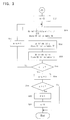
- FIG. 1 is a block diagram of one embodiment of a controller 1 for an injection molding machine which also configures an ejector controller of the present invention.
- the controller 1 has a CNC-CPU 25 which is a microprocessor for numerical control, a PC-CPU 21 which is a microprocessor for a programmable controller, a servo CPU 22 which is a microprocessor for servo control, and a pressure monitor CPU 20 which performs the sampling processing of the signals from sensors provided on the injection molding machine main body side to detect various pressures such as the injection pressure through an A/D converter 12 and which stores the signals into a RAM 14, and it can perform the information transmission between the respective microprocessors by selecting the mutual input and output through a bus 30.
- CNC-CPU 25 which is a microprocessor for numerical control
- PC-CPU 21 which is a microprocessor for a programmable controller
- a servo CPU 22 which is a microprocessor for servo control
- a pressure monitor CPU 20 which performs the sampling processing of the signals from sensors provided on the injection molding machine main body side to detect various pressures such as the injection pressure through an A/D converter 12 and which stores the signals
- a ROM 15 which stores a sequence program or the like for controlling the sequential operation of the injection molding machine, and a RAM 16 which is used for the temporary storage of the arithmetic data or the like are connected, and to the CNC-CPU 25, a ROM 27 which stores the automatic operation program for controlling throughout the injection molding machine or the like, and a RAM 28 which is used for the temporary storage of the arithmetic data or the like are connected.
- ROM 17 which stores the control program exclusively used for the servo control for performing the processing of a position loop, a speed loop, and a current loop
- RAM 18 which is used for the temporary storage of the data
- a ROM 13 which stores the control program of the control performed by the above described pressure monitor CPU 20, and the above described RAM 14 which stores the pressure detected by various sensors or the like are connected.
- a servo amplifier 19 is connected, which drives the servo motor 10 of individual axes for the die clamping, injection, screw rotation, ejector, or the like on the basis of the command from the above described CPU 22, and the output from a position and speed detector 11 attached to the servomotor 10 of individual axes is returned to the servo CPU 22.
- the present position of individual axes is calculated by the servo CPU 22 on the basis of the feedback signal of the position from the position and speed detector 11, and it is renewed and stored in the present position storing register for individual axes.
- FIG. 1 shows only the servomotor 10 which drives an ejector axis (ejector mechanism), and the position and speed detector 11 which is attached to the above described servomotor 10 to detect the position of an ejector pin or the like on the basis of the rotational position of the above described servomotor, and every configuration of individual axes for the clamping, injection, or the like is similar to this.
- An interface 23 is an input and output interface which receives a signal from a limit switch or a control panel arranged at each part of the injection molding machine main body and which transmits various commands to peripheral installations of the injection molding machine or the like.
- a manual data input device 29 with a display is connected to the bus 30 through a CRT display circuit 26, and it can perform selection of the graphic display screen or functional menu, and input operation of various data or the like, and it has numerical keys for the numerical data input and various function keys or the like.
- the display device may be a device using a liquid crystal.
- a data storing RAM 24 configured by a nonvolatile memory is a memory for the molding data storage which stores the molding condition relating to the injection molding works and various set values, parameters, macro variables or the like. Furthermore, relating to the present invention, a table for storing the data of the estimated disturbance load torque values to be described later is provided in this data storing RAM 24.
- the PC-CPU 21 controls the sequential operation of the total of the injection molding machine
- the CNC-CPU 25 performs the distribution of the movement commands to the servomotor of individual axes on the basis of the operating program of the ROM 27, the molding conditions stored in the data storing RAM 24, or the like
- the servo CPU 22 performs servo controls such as position loop control, speed loop control, and further, current loop control similarly to the prior art on the basis of the movement commands distributed to individual axes and the feedback signals of the position and speed detected by the position and speed detector 11 or the like, and it performs the so-called digital servo processing.
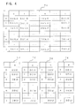
- the above described configuration is similar to that of the controller of a conventional electrically-powered injection molding machine, and the ejector controller of the present invention is configured by this controller 1. Then, it is different from the conventional controller in that in the data storing RAM 24 configured by a nonvolatile memory, tables TA, TB, TC, TD, TE are provided, which store the data of values of disturbance load torques estimated for each specific sampling period by the disturbance estimating observer, the average value thereof as the reference disturbance load torque, the upper limit value and lower limit value of the permissible range determined from the average value, and the deviation between the estimated disturbance load torque value and the average value, and that in the ROM 17 connected to the servo CPU 22, a program of the disturbance estimating observer which is assembled in the speed loop to estimate the disturbance torque applied to the servomotor 10, and a program of processing for detecting an abnormal load in the section of the ejector stroke on the basis of the estimated disturbance load torque determined by the processing of this disturbance estimating observer are stored.
- FIG. 5 is a figure showing the display screen of the abnormal load detection condition setting in the ejector operation accessed by operating the manual data input device 29 with a display.
- FIG. 5 shows an example in which [ejector abnormal load detection control ON] is set so that the detection control operation of an abnormal load applied to the ejector may be performed.
- the number T of cycles after the start of the automatic molding cycle in which the detection control operation of an abnormal load is not performed is set.
- the average value of the estimated disturbance load torques estimated by the disturbance estimating observer is the reference disturbance load torque, and shift amounts ⁇ K are set, which are added to this reference disturbance load torque so that the upper limit value and lower limit value of the permissible range may be determined.
- ⁇ K are set as shift amounts of the same amount for both the upper limit value and lower limit value, but the shift amounts for determining the upper limit value and lower limit value may be set at values different from each other.
- the upper limit value may be a suitable value within the range of giving no damage to the die.
- the lower limit value is a value for detecting charging failure of resin or the like, and an optimum shift amount for this detection may be set.
- a proper shift amount is set in advance.
- the average (waveform) of the estimated disturbance load torques at the time of the ejector operation is determined as the reference disturbance load torque, and therefore, this average is displayed by a graph as shown in FIG. 5, and on the basis of this average waveform, the shift amount +K of the upper limit value is set so that it may be the maximum value of the permissible range of giving no damage to the die, while the shift amount -K is set so that it may be a value smaller than the average as this reference disturbance load torque but a little larger than the load torque during an ejector operation with no molded product.
- the servo CPU 22 starts the processing shown by the flow chart in FIG. 2 and FIG. 3.
- the servo CPU 22 sets a shot counter SC for counting the number of injections to be described later at [1], and sets a pointer a, which shows the storing position of the table TA, which is provided in the data storing RAM 24 for storing the data DA of the estimated disturbance load torque in the sampling period in the stroke section of the ejector operation, at [0], and sets a flag F at [0].
- tables TA, TB, TC, TD, TE for storing the estimated disturbance load torque or the like, all stored data are also cleared.
- the servo CPU 22 judges whether the shot counter SC exceeds the set number T of cycles at which the ejector abnormal load detection control is not performed (step S1), and when not exceeding, the above described processing of the ejector abnormal load detection control finishes.
- the shot counter SC is increased by [1] each time one molding cycle finishes, and it is increased in the processing period other than this processing of the ejector abnormal load detection control.
- step S2 the procedure proceeds to step S2 from step S1, and whether the ejector operation is started or not is judged. This judgment is similar to that of the prior art, and it is made on the basis of the position of a movable die or the like.
- an index n of sampling is set at [0] (step S3), and the estimated disturbance load torque Y (n) estimated by the processing of the disturbance estimating observer which is assembled in the speed loop and is performed together with the speed loop processing is read (step S4).
- the processing of this disturbance estimating observer since the processing of this disturbance estimating observer has already been well known in Japanese Patent Laid-Open No. 10-119107 or the like, the concrete processing will be omitted.
- step S5 whether the flag F is set at [1] or not is judged (step S5), and when not at [1], the procedure proceeds to step S8.
- This flag F is set at [1] when all data for obtaining the average value as the reference disturbance load torque are obtained as described later, and at the beginning, it is set at [0] since all data for obtaining the average of the set numbers of times of the ejector operation are not obtained, and the procedure proceeds to step S8.
- the determined estimated disturbance load torque Y (n) is stored in the table TA as the data DA (a, n).
- the determined estimated disturbance load torque Y (n) is stored as the data DA (a, n) in the address corresponding to the indexes a, n of the table TA on the basis of the index a which shows the number of ejector operations (molding cycles), and the index n which shows the number of samplings in that ejector operations.
- step S9 whether the ejector is at stroke end or not is judged (step S9), and when the ejector is not at stroke end, the index n is increased by [1] (step S10), and the step returns to step S4.
- this judgment of whether the ejector is at stroke end or not is made on the basis of the position of the servomotor 10 which is detected by the position and speed detector 11 attached to the servomotor for driving the ejector axis and which is stored in the present position storing register.
- the ejector mechanism is a mechanism in which the rotation of the servomotor is changed to the linear movement by using a mechanism for converting the rotational movement of a ball screw or the like into the linear movement so that the ejector pin or the like may linearly be moved, and there is a one-to-one relation between the rotation of the servomotor and the projecting position of the ejector pin, and when the rotational position of the servomotor is known, the projecting position of the ejector pin can be known.
- step S4 the processing at steps S4, S5, S8, S9 and S10 is repeatedly performed for each specific sampling period (for each speed loop processing period), and when the ejector is at stroke end, the procedure proceeds to step S11 from step S9, and the value of the index n is stored in the register as the sampling total number j of projecting strokes in the ejector operations.
- the estimated disturbance load torque Y (n) at the time of the ejector operation determined by the disturbance estimating observer is stored in the table TA as the data DA (a, n).
- step S12 the index n is cleared to [0] again (step S12), and the processing at steps S13, S14 and S15 is performed for obtaining the average value DB (n) of the estimated disturbance load torques as the reference disturbance load torque, and the upper limit value DC (n) and lower limit value DD (n) of the permissible range.
- the data of the estimated disturbance values in the ejector operations (molding cycles) 0 to i, at the n-th sampling time, which are stored in the table TA, are added, and the added data are divided by the number (i+1) of ejector operations (molding cycles) so that the average value DB (n) may be obtained, and the obtained DB (n) is stored in the table TB as shown in FIG. 4 (step S13).
- the set shift amount +K is added to this average value DB (n) so that the upper limit value DC (n) of the permissible range may be obtained, and the obtained DC (n) is stored in the table TC as shown in FIG. 4 (step S14). Furthermore, the set shift amount -K is added to this average value DB (n) so that the lower limit value DD (n) of the permissible range may be determined, and the obtained DD (n) is stored in the table TD as shown in FIG. 4 (step S15).
- step S17 the index n becomes the sampling total number j (step S17)
- step S17 the index n is increased by [1] (step S17) and in the meantime, the above described averaging processing (step S13) and the processing for determining the upper limit value and lower limit value of the permissible range (steps S14, S15) are performed.
- step S18 the procedure proceeds to step S18 from step S16, and the index a is increased by [1], and whether the above described index a exceeds the value of the final address i corresponding to the number of ejector operations (molding cycles) stored in the table TA or not is judged (step S19). That is, whether the data of the estimated disturbance load torque have been written in the final address i of the table TA by the above described ejector operation or not is judged.
- the value of the index a has not exceeded the value of the final address i, the abnormal detection processing in the above described ejector operation finishes.
- the average value DB (n), and the upper limit value DC (n) and lower limit value DD (n) of the permissible range which are determined by the processing at steps S13 to S16 can be accurate values.
- the upper limit value and lower limit value of the permissible range are determined by adding shift amounts +K, -K to each of the determined average values DB (0) to DB (j).
- step S18 the index a is increased, and when the value of the above described index a exceeds the value of i, the procedure proceeds to step S20 from step S19, and the flag F is set at [1], and the index a is cleared to [0] (step S20).
- the step returns to the beginning at the time of the ejector operation of the next molding cycle, and the index a is cleared to [0] so that the data may be stored again from the address [0].
- (i+1) pieces of data of the ejector operations of the latest molding cycles before (prior to) the ejector operation of the present molding cycle are stored at all times.
- step S6 the procedure proceeds to step S6 from step S5, and the average value DB (n) stored in the table TB is subtracted from the estimated disturbance load torque Y (n) obtained by the disturbance estimating observer so that the deviation DE (n) between the determined estimated disturbance load torque Y (n) and the average value DB (n) may be obtained, and the obtained DE (n) is stored in the table TE as shown in FIG. 4.
- step S7 whether or not the estimated disturbance load torque Y (n) is out of the permissible range, having exceeded the upper limit value DC (n) or lower limit value DD (n) of the permissible range stored in tables TC, TD is judged (step S7), and when it is within the permissible range, the procedure proceeds to step S8, and when it is out of the permissible range, the procedure proceeds to step S22, and a load abnormal signal indicating the fact that a load out of the permissible range has been applied to the ejector axis is outputted, and an alarm processing for stopping the operation of the servomotor 10 or the like is performed, and the abnormal load detection processing of this ejector operation finishes.
- the average value as the reference disturbance load torque is obtained by the estimated disturbance load torques at the time of the ejector operations in the latest (i+1) molding cycles, and both the upper limit value and lower limit value of the permissible range shifts in association with this average value, and whether it is within the range between the lower limit value (waveform) smaller than the average value by the set shift amount K and the upper limit value (waveform) larger by the set value K or not is judged at all times, and therefore, even when the average value is fluctuated depending on the change of temperature or the like, an optimum permissible range can be maintained.
- the upper limit value and lower limit value of the permissible range that is, the permissible range for judging an abnormal load at the time of the ejector operation is automatically determined by the average value of the estimated disturbance load torques at the time of the normal ejector operation, and an abnormal is judged by this determined permissible range, and therefore, it is unnecessary to set the permissible range for judging this abnormal load by experience and perception similarly to the prior art, and at any time, an optimum permissible range can automatically be set.
- the estimated disturbance load torque Y (n) is not stored any more in the table TA whenever it exceeds the upper limit value DC (n) or lower limit value DD (n) of the permissible range.
- the waveform of the estimated disturbance load torque at the time of the latest ejector operation, stored in the table TA, and the related data stored in tables TB, TC, TD, TE can be displayed by graphs on the CRT screen as the display screen as shown in FIG. 5.
- FIG. 5 shows an example of displaying of the waveform of the estimated disturbance load torque at the time of the latest ejector operation, stored in the table TA, the waveform of the average value of the reference disturbance load torque stored in the table TB, and the waveforms of the upper limit value and lower limit value of the permissible rage stored in the tables TC and TD respectively.
- the operator can reset the shift amounts, +K, -K, for determining the upper limit value and lower limit value of the permissible range to optimum values by referring to these displayed waveforms.
- the data to be stored in the table TE by a graph, instead of or in addition to displaying of the waveform of the estimated disturbance load torque at the time of the latest ejector operation on the basis of the data stored in the table TA. Since this data to be stored in the table TE stores the deviation between the average value as the reference disturbance load torque and the estimated disturbance load torque at the time of the latest ejector operation, the waveform showing a deviation from the average value is displayed, so that the divergence from the average value can directly be seen, and there is such an effect that the present situation can be grasped more clearly.
- the upper limit value and lower limit value of the permissible range which give a standard for discriminating an abnormal load may be changed according to the position of the ejector pin in the stroke, so that an abnormal load can be discriminated more accurately.
- this set value when one set value is applied uniformly to the entire range of the stroke of the ejector operation, this set value may be too large in a certain position, so that a problem of being unable to detect an abnormal load though the abnormal load occurs may be caused, and on the contrary, when the set value is too small, at a certain position, a phenomenon of determination of an abnormal load in spite of a normal ejector operation may be produced.
- the permissible range which gives a standard for discriminating an abnormal load is changed according to the position of the ejector pin in the stroke of the ejector operation, and therefore, an abnormal load can be detected more accurately than that in the case of using a constant value as the standard of discrimination, so that the die can accurately be protected.
- the graphic display of the latest estimated disturbance load torque, the average value, the upper limit value and lower limit value of the permissible range, or the like are shown as a function of time. However, these can be shown as a function of the position of the ejector pin or the rotational position of the servomotor for driving the ejector axis.
- the estimated disturbance load torque obtained by the disturbance estimating observer is stored each time the servomotor 10 moves through a specific amount, and on the basis of this stored data, the average value and the upper limit value and lower limit value of the permissible range are determined and graphically displayed on the screen. Furthermore, it is also possible to perform the judgment of whether it is an abnormal load or not with respect to this position.
- the gathering of the estimated disturbance load torques is performed for each specific period in a way similar to that of this embodiment, and the rotational position of the servomotor 10 at that moment is stored, and on the basis of this position, the estimated disturbance load torque is displayed on the screen.
- the average value of the estimated disturbance torques may be obtained from the estimated disturbance torques to be obtained at specific positions, which are given by the interpolation of the estimated disturbance torques actually obtained at any positions, or which are given by the estimated disturbance torques actually obtained at any positions nearest to the specific positions. Then, the obtained average value may be graphically displayed on a screen.
Landscapes
- Engineering & Computer Science (AREA)
- Manufacturing & Machinery (AREA)
- Mechanical Engineering (AREA)
- Injection Moulding Of Plastics Or The Like (AREA)
- Moulds For Moulding Plastics Or The Like (AREA)
Abstract
Description
Claims (9)
- An ejector controller for an injection molding machine which drives and controls a servomotor to drive an ejector axis, comprising:load detecting means for detecting a load applied to said servomotor;means for detecting the load applied to the servomotor at the time of ejector operation for each molding cycle by means of said load detecting means, and storing the load with respect to the ejector operation time or ejector position for the latest one or a plurality of ejector operations before the present molding cycle;means for obtaining a reference load from the stored load;means for determining a permissible upper limit value from the reference load; anddiscriminating means for outputting an abnormal signal when the load at the time of the present ejector operation has exceeded said permissible upper limit value.
- The ejector controller according to claim 1, wherein, when the abnormal signal is outputted, the load applied to the servomotor at the time of that ejector operation is excluded from the data for determining the reference load.
- The ejector controller according to claim 1 or 2, wherein:said permissible upper limit value is set on a screen; andthe load applied to the servomotor at the time of the present ejector operation, the reference load and the permissible upper limit value, or a deviation between the reference load and the load at the time of the present ejector operation and the permissible upper limit value are graphically displayed on the screen with respect to the time or ejector position.
- The ejector controller according to any preceding claim, wherein:said means for determining a permissible upper limit value also determines a permissible lower limit value from said reference load; andsaid discriminating means also outputs the abnormal signal when the load applied to the servomotor has exceeded said permissible lower limit value.
- The ejector controller according to any preceding claim, wherein the load applied to the servomotor for the predetermined number of cycles after starting of a full automatic molding is excluded from the data for determining the reference load.
- The ejector controller according to claim 5, wherein said predetermined number of cycles after starting of a full automatic molding for which the load applied to the servomotor is excluded from data for determining the reference load is set on a screen of display means.
- The ejector controller according to any preceding claim, wherein said reference load is determined. by the average value of the loads applied to the servomotor at the time of ejector operations in a plurality of molding cycles before the present molding cycle.
- The ejector controller according to any preceding claim, wherein said load detecting means for detecting a load applied to said servomotor is a disturbance estimating observer which estimates a load torque.
- An injection molding machine which comprises an ejector controller according to any preceding claim.
Applications Claiming Priority (2)
| Application Number | Priority Date | Filing Date | Title |
|---|---|---|---|
| JP21356799A JP3441680B2 (en) | 1999-07-28 | 1999-07-28 | Ejector control device for injection molding machine |
| JP21356799 | 1999-07-28 |
Publications (3)
| Publication Number | Publication Date |
|---|---|
| EP1072386A2 true EP1072386A2 (en) | 2001-01-31 |
| EP1072386A3 EP1072386A3 (en) | 2001-07-18 |
| EP1072386B1 EP1072386B1 (en) | 2003-10-29 |
Family
ID=16641358
Family Applications (1)
| Application Number | Title | Priority Date | Filing Date |
|---|---|---|---|
| EP00306442A Expired - Lifetime EP1072386B1 (en) | 1999-07-28 | 2000-07-28 | Ejector controller for injection molding machine |
Country Status (4)
| Country | Link |
|---|---|
| US (1) | US6527534B1 (en) |
| EP (1) | EP1072386B1 (en) |
| JP (1) | JP3441680B2 (en) |
| DE (1) | DE60006193T2 (en) |
Cited By (8)
| Publication number | Priority date | Publication date | Assignee | Title |
|---|---|---|---|---|
| EP1147874A3 (en) * | 2000-04-18 | 2003-04-23 | Sumitomo Heavy Industries, Ltd. | Moulded product ejection checking device |
| EP1382429A1 (en) * | 2002-07-17 | 2004-01-21 | Fanuc Ltd | Ejector unit of injection molding machine and method of detecting protrusion start position of ejector pin |
| CN103085232A (en) * | 2011-09-26 | 2013-05-08 | 恩格尔奥地利有限公司 | Driving device for injection molding machine |
| WO2016146327A1 (en) * | 2015-03-19 | 2016-09-22 | Krones Ag | Method for collision monitoring |
| WO2019185594A1 (en) * | 2018-03-27 | 2019-10-03 | Kraussmaffei Technologies Gmbh | Method for the automatic process monitoring and process diagnosis of a piece-based process (batch production), in particular an injection-molding process, and machine that performs the process or set of machines that performs the process |
| CN113910561A (en) * | 2020-07-10 | 2022-01-11 | 恩格尔奥地利有限公司 | Method for automatically monitoring at least one production process |
| DE102024115524A1 (en) * | 2024-06-04 | 2025-12-04 | Focke & Co. (Gmbh & Co. Kg) | Method for monitoring an automatic machine for the manufacture or packaging of smoking, hygiene, food or pharmaceutical products |
| EP4667184A1 (en) * | 2024-06-17 | 2025-12-24 | The Japan Steel Works, Ltd. | Injection molding machine and determination method |
Families Citing this family (22)
| Publication number | Priority date | Publication date | Assignee | Title |
|---|---|---|---|---|
| JP4108906B2 (en) * | 2000-07-11 | 2008-06-25 | 東芝機械株式会社 | Abnormality detection method in injection molding machine |
| JP2004106272A (en) * | 2002-09-17 | 2004-04-08 | Toshiba Mach Co Ltd | Method for detecting abnormality in injection molding machine |
| JP4585263B2 (en) * | 2003-10-16 | 2010-11-24 | 東芝機械株式会社 | Monitoring method in injection molding machine |
| US7252796B2 (en) * | 2003-10-16 | 2007-08-07 | Toshiba Machine Co., Ltd. | Ejecting load monitoring method for injection molding machine |
| JP3892852B2 (en) | 2004-02-17 | 2007-03-14 | ファナック株式会社 | Load detection device for electric injection molding machine |
| US7792152B1 (en) | 2004-06-08 | 2010-09-07 | Owlink Technology, Inc. | Scheme for transmitting video and audio data of variable formats over a serial link of a fixed data rate |
| JP4654063B2 (en) * | 2005-03-31 | 2011-03-16 | 株式会社ユーシン精機 | Mold take-out device |
| JP4174533B2 (en) * | 2006-06-30 | 2008-11-05 | ファナック株式会社 | Ejector control device for injection molding machine |
| JP4167282B2 (en) * | 2006-10-27 | 2008-10-15 | 日精樹脂工業株式会社 | Support device for injection molding machine |
| JP4199283B2 (en) * | 2007-05-28 | 2008-12-17 | ファナック株式会社 | Injection molding machine |
| JP4568350B2 (en) * | 2008-05-26 | 2010-10-27 | ファナック株式会社 | Abnormality detection device for injection molding machine |
| JP5180356B1 (en) | 2011-09-29 | 2013-04-10 | ファナック株式会社 | Abnormality detection device for injection molding machine |
| JP5155432B1 (en) | 2011-10-18 | 2013-03-06 | ファナック株式会社 | Abnormality detection device for injection molding machine |
| JP5155439B1 (en) | 2011-12-20 | 2013-03-06 | ファナック株式会社 | Abnormality detection device for injection molding machine |
| AT13187U8 (en) | 2012-04-02 | 2013-12-15 | Engel Austria Gmbh | Ejector device for an injection molding machine |
| BE1021675B1 (en) * | 2013-04-26 | 2016-01-05 | Gb Boucherie Nv | INJECTION MOLDING |
| JP2014240162A (en) * | 2013-06-12 | 2014-12-25 | ファナック株式会社 | Valve gate control device of injection molding machine |
| JP5937637B2 (en) * | 2014-04-30 | 2016-06-22 | ファナック株式会社 | Control device that outputs a switching notice signal when switching sequence programs |
| CN107614213B (en) * | 2015-05-20 | 2021-03-09 | 日产自动车株式会社 | Fault diagnosis device and fault diagnosis method |
| JP6378236B2 (en) | 2016-03-25 | 2018-08-22 | ファナック株式会社 | Abnormality detection device for injection molding machine |
| JP6557272B2 (en) | 2017-03-29 | 2019-08-07 | ファナック株式会社 | State determination device |
| CN110850825B (en) * | 2019-11-13 | 2021-06-08 | 武汉恒力华振科技有限公司 | Industrial process data processing method based on event time |
Family Cites Families (13)
| Publication number | Priority date | Publication date | Assignee | Title |
|---|---|---|---|---|
| JPH06339292A (en) | 1993-04-02 | 1994-12-06 | Fanuc Ltd | Force controlling method by estimation of disturbance load |
| JPS60190829A (en) * | 1984-03-12 | 1985-09-28 | Sumitomo Heavy Ind Ltd | Apparatus for monitoring molded-product releasing |
| JPS6166621A (en) * | 1984-09-11 | 1986-04-05 | Sumitomo Heavy Ind Ltd | Discreminating device for quality of molded product |
| JPS6266917A (en) * | 1985-09-18 | 1987-03-26 | Toshiba Mach Co Ltd | Quality discriminating device for product of injection molding machine |
| JPS633925A (en) * | 1986-06-24 | 1988-01-08 | Fanuc Ltd | Injection molder equipped with function of printing alarm contents |
| JP2568101B2 (en) * | 1988-03-26 | 1996-12-25 | 株式会社日本製鋼所 | Edge control method and apparatus for electric injection molding machine |
| EP0656250A4 (en) | 1993-04-20 | 1997-12-17 | Sankyokasei Kabushiki Kaisha | Apparatus for controlling gate cut and ejection for an injection molding machine and method for controlling the same. |
| US5470218A (en) * | 1993-07-07 | 1995-11-28 | Wheaton Inc. | Graphical interface driven injection blow molding apparatus |
| US5469038A (en) * | 1994-05-10 | 1995-11-21 | Cincinnati Milacron Inc. | Method for compensating for efficient variations in an electric motor |
| JPH0866893A (en) | 1994-08-24 | 1996-03-12 | Fanuc Ltd | Collision detecting method |
| JP3079047B2 (en) | 1996-10-22 | 2000-08-21 | ファナック株式会社 | Movable member collision detection device for electric injection molding machine |
| JP3088403B2 (en) | 1999-01-11 | 2000-09-18 | ファナック株式会社 | Machine power consumption display |
| JP3080617B1 (en) | 1999-07-19 | 2000-08-28 | ファナック株式会社 | Mold protection device for injection molding machine |
-
1999
- 1999-07-28 JP JP21356799A patent/JP3441680B2/en not_active Expired - Fee Related
-
2000
- 2000-07-27 US US09/626,962 patent/US6527534B1/en not_active Expired - Lifetime
- 2000-07-28 EP EP00306442A patent/EP1072386B1/en not_active Expired - Lifetime
- 2000-07-28 DE DE60006193T patent/DE60006193T2/en not_active Expired - Lifetime
Cited By (14)
| Publication number | Priority date | Publication date | Assignee | Title |
|---|---|---|---|---|
| EP1147874A3 (en) * | 2000-04-18 | 2003-04-23 | Sumitomo Heavy Industries, Ltd. | Moulded product ejection checking device |
| EP1382429A1 (en) * | 2002-07-17 | 2004-01-21 | Fanuc Ltd | Ejector unit of injection molding machine and method of detecting protrusion start position of ejector pin |
| CN103085232A (en) * | 2011-09-26 | 2013-05-08 | 恩格尔奥地利有限公司 | Driving device for injection molding machine |
| CN103085232B (en) * | 2011-09-26 | 2016-02-03 | 恩格尔奥地利有限公司 | For the drive unit of injection machine |
| US10218174B2 (en) | 2015-03-19 | 2019-02-26 | Krones Ag | Method for collision monitoring |
| CN106489234A (en) * | 2015-03-19 | 2017-03-08 | 克朗斯股份公司 | The method of monitoring collision |
| WO2016146327A1 (en) * | 2015-03-19 | 2016-09-22 | Krones Ag | Method for collision monitoring |
| CN106489234B (en) * | 2015-03-19 | 2021-04-06 | 克朗斯股份公司 | Methods of Monitoring Collision |
| EP3272004B1 (en) | 2015-03-19 | 2022-03-09 | Krones AG | Method for collision monitoring |
| WO2019185594A1 (en) * | 2018-03-27 | 2019-10-03 | Kraussmaffei Technologies Gmbh | Method for the automatic process monitoring and process diagnosis of a piece-based process (batch production), in particular an injection-molding process, and machine that performs the process or set of machines that performs the process |
| CN113910561A (en) * | 2020-07-10 | 2022-01-11 | 恩格尔奥地利有限公司 | Method for automatically monitoring at least one production process |
| CN113910561B (en) * | 2020-07-10 | 2024-06-04 | 恩格尔奥地利有限公司 | Method for automatically monitoring at least one production process |
| DE102024115524A1 (en) * | 2024-06-04 | 2025-12-04 | Focke & Co. (Gmbh & Co. Kg) | Method for monitoring an automatic machine for the manufacture or packaging of smoking, hygiene, food or pharmaceutical products |
| EP4667184A1 (en) * | 2024-06-17 | 2025-12-24 | The Japan Steel Works, Ltd. | Injection molding machine and determination method |
Also Published As
| Publication number | Publication date |
|---|---|
| JP2001038775A (en) | 2001-02-13 |
| EP1072386B1 (en) | 2003-10-29 |
| US6527534B1 (en) | 2003-03-04 |
| DE60006193T2 (en) | 2004-04-22 |
| EP1072386A3 (en) | 2001-07-18 |
| DE60006193D1 (en) | 2003-12-04 |
| JP3441680B2 (en) | 2003-09-02 |
Similar Documents
| Publication | Publication Date | Title |
|---|---|---|
| US6527534B1 (en) | Ejector controller of injection molding machine | |
| JP3080617B1 (en) | Mold protection device for injection molding machine | |
| US7261009B2 (en) | Monitor for injection molding machine | |
| US5792395A (en) | Plasticization control method for an injection molding machine | |
| US6526360B1 (en) | Power consumption display device for machine | |
| US6616872B2 (en) | Method of and apparatus for determining separating force of molded product from mold | |
| JP3795323B2 (en) | Foreign matter detection method for injection molding machine | |
| EP1449633B1 (en) | Shear energy monitoring device for an injection molding machine | |
| EP1614522B1 (en) | Monitoring device and monitoring method for injection molding machine | |
| KR960016033B1 (en) | Method for discriminating non-defective from defective in injection molding machine | |
| KR970002297B1 (en) | Back pressure control method and apparatus for electric injection molding machine | |
| JPH0358821A (en) | Injection pressure control method for motorized injection molding machine | |
| JP7399108B2 (en) | motion controller | |
| EP1147874B1 (en) | Moulded product ejection checking device | |
| JP3135416B2 (en) | Method and apparatus for judging product quality of injection molding machine | |
| JP3556236B2 (en) | Monitor for injection molding machine | |
| JP3581164B2 (en) | Product quality judgment method and product quality judgment device for injection molding machine | |
| EP0451298A1 (en) | Method of setting molding condition in injection molding machine | |
| JPH06226807A (en) | Detecting method for abnormal pressure of injection molding machine | |
| JPH0260726A (en) | Injection monitor system of injection molding machine | |
| JPH04249128A (en) | Monitor data and molding condition printing method for injection molding machine | |
| JP2002028958A (en) | Method for controlling plasticization in injection molding machine |
Legal Events
| Date | Code | Title | Description |
|---|---|---|---|
| PUAI | Public reference made under article 153(3) epc to a published international application that has entered the european phase |
Free format text: ORIGINAL CODE: 0009012 |
|
| AK | Designated contracting states |
Kind code of ref document: A2 Designated state(s): DE |
|
| AX | Request for extension of the european patent |
Free format text: AL;LT;LV;MK;RO;SI |
|
| PUAL | Search report despatched |
Free format text: ORIGINAL CODE: 0009013 |
|
| RIC1 | Information provided on ipc code assigned before grant |
Free format text: 7B 29C 45/76 A, 7G 05B 19/4062 B, 7B 29C 45/84 B |
|
| AK | Designated contracting states |
Kind code of ref document: A3 Designated state(s): AT BE CH CY DE DK ES FI FR GB GR IE IT LI LU MC NL PT SE |
|
| AX | Request for extension of the european patent |
Free format text: AL;LT;LV;MK;RO;SI |
|
| 17P | Request for examination filed |
Effective date: 20011031 |
|
| AKX | Designation fees paid |
Free format text: DE |
|
| 17Q | First examination report despatched |
Effective date: 20020917 |
|
| GRAH | Despatch of communication of intention to grant a patent |
Free format text: ORIGINAL CODE: EPIDOS IGRA |
|
| RIN1 | Information on inventor provided before grant (corrected) |
Inventor name: UENO, MASAYUKI Inventor name: UCHIYAMA, TATSUHIRO Inventor name: KAMIGUCHI, MASAO Inventor name: KOBAYASHI, MINORU |
|
| GRAA | (expected) grant |
Free format text: ORIGINAL CODE: 0009210 |
|
| GRAS | Grant fee paid |
Free format text: ORIGINAL CODE: EPIDOSNIGR3 |
|
| AK | Designated contracting states |
Kind code of ref document: B1 Designated state(s): DE |
|
| REF | Corresponds to: |
Ref document number: 60006193 Country of ref document: DE Date of ref document: 20031204 Kind code of ref document: P |
|
| RAP2 | Party data changed (patent owner data changed or rights of a patent transferred) |
Owner name: FANUC LTD |
|
| PLBE | No opposition filed within time limit |
Free format text: ORIGINAL CODE: 0009261 |
|
| STAA | Information on the status of an ep patent application or granted ep patent |
Free format text: STATUS: NO OPPOSITION FILED WITHIN TIME LIMIT |
|
| 26N | No opposition filed |
Effective date: 20040730 |
|
| REG | Reference to a national code |
Ref country code: DE Ref legal event code: R082 Ref document number: 60006193 Country of ref document: DE Representative=s name: HASELTINE LAKE LLP, DE |
|
| PGFP | Annual fee paid to national office [announced via postgrant information from national office to epo] |
Ref country code: DE Payment date: 20170725 Year of fee payment: 18 |
|
| REG | Reference to a national code |
Ref country code: DE Ref legal event code: R119 Ref document number: 60006193 Country of ref document: DE |
|
| PG25 | Lapsed in a contracting state [announced via postgrant information from national office to epo] |
Ref country code: DE Free format text: LAPSE BECAUSE OF NON-PAYMENT OF DUE FEES Effective date: 20190201 |