EP1072380A2 - Weather strip and process for manufacturing the same - Google Patents
Weather strip and process for manufacturing the same Download PDFInfo
- Publication number
- EP1072380A2 EP1072380A2 EP00115681A EP00115681A EP1072380A2 EP 1072380 A2 EP1072380 A2 EP 1072380A2 EP 00115681 A EP00115681 A EP 00115681A EP 00115681 A EP00115681 A EP 00115681A EP 1072380 A2 EP1072380 A2 EP 1072380A2
- Authority
- EP
- European Patent Office
- Prior art keywords
- extruded
- molded
- thermoplastic elastomer
- attachment
- weather strip
- Prior art date
- Legal status (The legal status is an assumption and is not a legal conclusion. Google has not performed a legal analysis and makes no representation as to the accuracy of the status listed.)
- Granted
Links
Images





Classifications
-
- B—PERFORMING OPERATIONS; TRANSPORTING
- B29—WORKING OF PLASTICS; WORKING OF SUBSTANCES IN A PLASTIC STATE IN GENERAL
- B29C—SHAPING OR JOINING OF PLASTICS; SHAPING OF MATERIAL IN A PLASTIC STATE, NOT OTHERWISE PROVIDED FOR; AFTER-TREATMENT OF THE SHAPED PRODUCTS, e.g. REPAIRING
- B29C45/00—Injection moulding, i.e. forcing the required volume of moulding material through a nozzle into a closed mould; Apparatus therefor
- B29C45/14—Injection moulding, i.e. forcing the required volume of moulding material through a nozzle into a closed mould; Apparatus therefor incorporating preformed parts or layers, e.g. injection moulding around inserts or for coating articles
- B29C45/14336—Coating a portion of the article, e.g. the edge of the article
- B29C45/14409—Coating profiles or strips by injecting end or corner or intermediate parts
-
- B—PERFORMING OPERATIONS; TRANSPORTING
- B60—VEHICLES IN GENERAL
- B60J—WINDOWS, WINDSCREENS, NON-FIXED ROOFS, DOORS, OR SIMILAR DEVICES FOR VEHICLES; REMOVABLE EXTERNAL PROTECTIVE COVERINGS SPECIALLY ADAPTED FOR VEHICLES
- B60J10/00—Sealing arrangements
- B60J10/15—Sealing arrangements characterised by the material
- B60J10/16—Sealing arrangements characterised by the material consisting of two or more plastic materials having different physical or chemical properties
-
- B—PERFORMING OPERATIONS; TRANSPORTING
- B60—VEHICLES IN GENERAL
- B60J—WINDOWS, WINDSCREENS, NON-FIXED ROOFS, DOORS, OR SIMILAR DEVICES FOR VEHICLES; REMOVABLE EXTERNAL PROTECTIVE COVERINGS SPECIALLY ADAPTED FOR VEHICLES
- B60J10/00—Sealing arrangements
- B60J10/15—Sealing arrangements characterised by the material
- B60J10/17—Sealing arrangements characterised by the material provided with a low-friction material on the surface
-
- B—PERFORMING OPERATIONS; TRANSPORTING
- B60—VEHICLES IN GENERAL
- B60J—WINDOWS, WINDSCREENS, NON-FIXED ROOFS, DOORS, OR SIMILAR DEVICES FOR VEHICLES; REMOVABLE EXTERNAL PROTECTIVE COVERINGS SPECIALLY ADAPTED FOR VEHICLES
- B60J10/00—Sealing arrangements
- B60J10/20—Sealing arrangements characterised by the shape
- B60J10/21—Sealing arrangements characterised by the shape having corner parts or bends
-
- B—PERFORMING OPERATIONS; TRANSPORTING
- B60—VEHICLES IN GENERAL
- B60J—WINDOWS, WINDSCREENS, NON-FIXED ROOFS, DOORS, OR SIMILAR DEVICES FOR VEHICLES; REMOVABLE EXTERNAL PROTECTIVE COVERINGS SPECIALLY ADAPTED FOR VEHICLES
- B60J10/00—Sealing arrangements
- B60J10/20—Sealing arrangements characterised by the shape
- B60J10/23—Sealing arrangements characterised by the shape assembled from two or more parts
- B60J10/233—Modular sealing arrangements, i.e. arrangements built up from a large number of joined modules
-
- B—PERFORMING OPERATIONS; TRANSPORTING
- B60—VEHICLES IN GENERAL
- B60J—WINDOWS, WINDSCREENS, NON-FIXED ROOFS, DOORS, OR SIMILAR DEVICES FOR VEHICLES; REMOVABLE EXTERNAL PROTECTIVE COVERINGS SPECIALLY ADAPTED FOR VEHICLES
- B60J10/00—Sealing arrangements
- B60J10/20—Sealing arrangements characterised by the shape
- B60J10/24—Sealing arrangements characterised by the shape having tubular parts
-
- B—PERFORMING OPERATIONS; TRANSPORTING
- B60—VEHICLES IN GENERAL
- B60J—WINDOWS, WINDSCREENS, NON-FIXED ROOFS, DOORS, OR SIMILAR DEVICES FOR VEHICLES; REMOVABLE EXTERNAL PROTECTIVE COVERINGS SPECIALLY ADAPTED FOR VEHICLES
- B60J10/00—Sealing arrangements
- B60J10/80—Sealing arrangements specially adapted for opening panels, e.g. doors
Definitions
- the present invention relates to a weather strip including a molded portion and an extruded portion, wherein the molded portion is integrally formed on the end of the extruded portion.
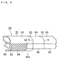
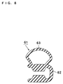
- FIGS. 5 to 8 show a conventional opening trim 50 of a weather strip.
- the opening trim 50 is formed by connecting integrally an end portion of a first extruded portion 51a to an end portion of a molded portion 61 and connecting the opposite end portion of the molded portion 61 to a second extruded portion 51b linearly.
- the symbol "S" designates a borderline, or an outline of the connecting end portions between the extruded portions 51a and 51b and the molded portion 61.
- Extruded portions 51a and 51b are substantially same components and will be referred to generically as extruded portion 51.
- the extruded portion 51 shown in FIG. 7 and the molded portion 61 shown in FIG. 8 comprise attachment portions 52 and 62, respectively, having a generally U-shaped cross section. Attachment portions 52 and 62 attach to a flange 2 at the periphery of a door opening of an automobile body 1, as shown in FIG. 9. Further, the extruded portion 51 and the molded portion 61 comprises a hollow sealing portion 53 and 63, respectively, which are deformable elastically under the pressing of a door 3 when the door 3 is closed. Further, either extruded portion 51a or 51b may include a covering lip portion 54 protruding from the attachment portion 52 and covering the edge of an inner garnish (not shown).
- the conventional opening trim 50 shown in FIGS. 5 to 8 is also illustrated within dotted circle A depicted in FIG. 9.
- the extruded portion 51 in FIG. 7 is integrally formed by co-extrusion molding the attachment portion 52, the hollow sealing portion 53 and the covering lip portion 54.
- a solid ethylene-propylene-diene copolymer (EPDM) rubber forms the attachment portion 52 and the covering lip portion 54, and a sponge EPDM rubber forms the hollow sealing portion 53.
- a metal insert 55 which may be made of separable pieces, is embedded in the attachment portion 52.
- a decorative cover 56 extending from the attachment portion 52 to the covering lip portion 54, is formed on the outer surface of the extruded portions 51a and 51b by thermal fusion bonding of a resin film, a thermoplastic elastomer film or a piece of fabric (cloth) after the completion of the extrusion molding process.
- the attachment portion 62 and the hollow sealing portion 63 are molded from a solid EPDM rubber to integrally form the molded portion 61 shown in FIG. 8. More specifically, the end portions of the two extruded portions 51a and 51b are held in a metal mold (not shown), whereby the end portions of the extruded portions 51a and 51b are set facing a cavity of the metal mold. Then, a solid EPDM rubber material is injected into the cavity and vulcanized to thereby form the molded portion 61. Simultaneously with this injection molding process, the extruded portions 51a and 51b are integrally connected to the resulting molded portion 61.
- the metal mold temperature required for the vulcanization of the rubber is as high as 180 to 200°C.
- Such a high metal mold temperature causes the decorative cover 56 to melt.
- the following countermeasures are employed. (1) When the decorative cover 56 extends to the end of the extruded portion 51, the decorative cover 56 is also held within the metal mold. When the injection molding process occurs, the decorative cover 56 is also melted which causes melting flaws or holding flaws to form at the segment where the ends of the extruded portion 51 are held. Then, as shown in FIG.
- a decorative cover portion 56x at the end portion of the extruded portion 51, a part of the attachment portion 52, and the covering lip portion 54 were removed together by a stepwise cutting process.
- the stepwise cutting was an extremely troublesome process.
- the decorative cover 56 is melted to form the molten flaws or holding flaws as described above.
- the buffing process was also extremely extra process.
- there were other manufacturing problem for example, in cases where a decorative cover 56 was applied with an embossed pattern, the embossed pattern was erased.
- the outer color differs from the molded portion 61 causing a deterioration in the appearance of the weather strip.
- the attachment portion 62 and the sealing portion 63 are formed of an identical material. So, if the design emphasis is placed on the softness of the rubber for sealing of the sealing portion 63, the rubber material may be made too soft. As a result, the gripping force of the attachment portion 62 to the flange is weakened.
- TPE thermoplastic elastomer
- This configuration is designed to obtain a load necessary for the elastic deformation of the sealing portion of the molded portion by forming the sealing portion with a soft or sponge TPE material, and to obtain the required gripping force of the molded portion by forming the attachment portion with the semi-rigid resin material.
- a first invention resides in a weather strip comprising an extruded portion and a molded portion which is integrally connected to an end portion of the extruded portion.
- the extruded portion comprises a sealing portion formed by extrusion molding a sponge rubber, soft TPE or sponge TPE and an attachment portion having a separable core member embedded therein and formed by co-extrusion molding from a solid rubber, low foamed rubber or TPE.
- the molded portion comprises a sealing portion formed of a soft TPE or sponge TPE and an attachment portion formed of a semi-rigid resin.
- the semi-rigid resin employed within the present invention has a hardness such that it does not lose its own shape after the molding process, and the concept of this semi-rigid resin also encompasses a thermoplastic elastomer.
- a second invention resides in a process for manufacturing a weather strip comprising an extruded portion and a molded portion wherein the molded portion is integrally connected to an end portion of the extruded portion.
- the process comprises the steps of setting the end portion of the extruded portion in a mold cavity.
- the extruded portion includes a sealing portion, formed by extrusion molding a sponge rubber, soft TPE or sponge TPE, and an attachment portion, having a separable core member embedded and formed by co-extrusion molding from a solid rubber, low foamed rubber or TPE.
- a semi-rigid resin material is injected into the mold cavity to form an attachment portion of the molded portion to integrally connect the attachment portion of the molded portion to the attachment portion of the extruded portion.
- a soft or sponge TPE material is injected into the mold cavity to form a sealing portion of the molded portion to integrally connect the sealing portion of the molded portion to the sealing portion of the extruded portion.
- the extruded portion may comprise a covering lip portion, which is formed integrally to the attachment portion of the extruded portion and protruding therefrom.
- the extruded portion further comprises a decorative cover formed of a resin, TPE or foamed material thereof and when the decorative cover is formed on the outer surface of the attachment portion or the covering lip portion of the extruded portion, the decorative cover can extend as far as the terminal edge of the end of the extruded portion without requiring stepwise cutting.
- the metal mold temperature is set to a temperature that does not melt the decorative cover.
- the metal mold temperature is preferably 60°C to 80°C.
- the TPE for the sealing portion of the molded portion preferably has a Shore A type hardness of 30° to 60°.
- the semi-rigid resin for the attachment portion of the molded portion preferably has a Shore D type hardness of 30° to 65°.
- the decorative cover and the attachment portion of the molded portion preferably have an identical color. No core member is embedded in the attachment portion of the molded portion.
- the molded portion may be formed in a linear shape or a curved shape.
- a solid rubber, low foamed rubber or TPE may be used as a molding material for the attachment portion of the extruded portion as in the conventional case.
- An EPDM solid rubber or EPDM low foamed rubber having a foaming ratio of 10% to 25% is preferable to use the material for the attachment portion of the extruded portion.
- a sponge rubber or soft or sponge TPE is applicable as a molding material for the sealing portion of the extruded portion as in the conventional case.
- "Rubber” embraces an EPDM rubber
- soft or sponge TPE embraces an olefin-based TPE (TPO) and styrene-based TPE (SBC).
- TPO olefin-based TPE
- SBC styrene-based TPE
- the sealing portion is a hollow or a lip. Especially, a hollow sealing portion is preferably used.
- TPE is applicable as a molding material for the sealing portion of the molded portion.
- TPE embraces an olefin-based TPE (TPO) and styrene-based TPE (SBC).
- a soft TPO is preferably used from the standpoint of adhesion with the attachment portion of the extruded portion or the molded portion.
- an olefin-based resin such as polyethylene or polypropylene having a Shore D type hardness of 30° to 65° may be used for example.
- a polyethylene resin is preferably used from the standpoint of adhesion relative to EPDM as an olefin-based rubber.
- the resin for the decorative cover a polyolefin resin such as polyethylene or polypropylene can be used for example.
- TPO and SBC or the like can be exemplified as the TPE for the decorative cover.
- a foamed material of the resin or TPE can also be used. It is preferred that a pattern such as an embossed pattern is illustrated on the surface of the decorative cover. Of course, when the pattern is formed, a design of an identical pattern is also provided on the outer surface for the attachment portion and/or the covering lip portion of the molded portion.
- An opening trim 10 of a weather strip is formed by connecting integrally an end portion of a first extruded portion 11a to an end portion of a molded portion 21 and connecting the opposite end portion of the molded portion to a second extruded portion 11b linearly.
- the symbol "S" designates a borderline, or an outline of the connecting end portions between the extruded portions 11a and 11b and the molded portion 21.
- the opening trim 10 of this first embodiment represents a portion shown in a dotted circle B in FIG. 9.
- Extruded portions 11a and 11b are substantially same components and will be referred to generically as extruded portion 11.
- the extruded portion 11 in FIG. 2 and the molded portion 21 in FIG. 3 comprises an attachment portion 12 and 22, respectively, having a generally U-shaped cross section. Attachment portions 12 and 22 attach to a flange 2 at the periphery of a door opening of an automobile body 1, as shown in FIG. 9. Further, the extruded portion 11 and the molded portion 21 comprises a hollow sealing portion 13 and 23, respectively, which are deformable elastically under the pressing of a door 3 when the door 3 is closed. Still further, the extruded portion 11 and the molded portion 21 include a covering lip portion 14 and 24, respectively, protruding from the corresponding attachment portion 12 or 22 and covering the edge of an inner garnish (not shown). The covering lip portion 14 of the extruded portion 11 may be provided on only one of the extruded portion 11a or 11b as disclosed in the conventional opening trim shown in FIG. 5.
- the extruded portion 11 shown in FIG. 2 is integrally formed by co-extrusion molding a solid EPDM rubber to form the attachment portion 12 and the covering lip portion 14 and a sponge EPDM rubber to form the hollow sealing portion 13.
- a metal insert 15, which may be separable pieces, is embedded in the attachment portion 12.
- a decorative cover 16, extending from the attachment portion 12 to the covering lip portion 14, is formed on the outer surface of the extruded portion 11 by bonding a TPE film after the completion of the extrusion molding process.
- the molded portion 21 shown in FIG. 3 is formed by integrally forming the attachment portion 22 and the covering lip portion 24 made of a polyethylene resin as a semi-rigid resin having a Shore D type hardness of about 40°. Further, the molded portion 21 is formed by integrally forming the hollow sealing portion 23 consisting of a soft TPO having Shore A type hardness of about 50°. Specifically, the end portions of extruded portions 11a and 11b are held on a metal mold (not shown), by the end portions of the extruded portions 11a and 11b that face a cavity of the metal mold.
- the attachment portion 22, the covering lip portion 24 and the hollow sealing portion 23 are integrally formed together.
- a polyethylene resin material for forming the attachment portion 22 and the covering lip portion 24 is injected from a gate 25 into the cavity, as shown by a dotted chain line in FIG. 3.
- a soft TPO is injected from a gate 26 into the cavity to form the hollow sealing portion 23, as shown by a dotted line in FIG. 3.
- the injection molding process of gate 25 and 26 occur almost simultaneously. Concurrently with this injection molding process, the extruded portions 11a and 11b are integrally connected to the resulting molded portion 21.
- the Shore D type hardness of the semi-rigid resin for the attachment portion 22 of the molded portion 21 is less than 30°, the shape of the attachment portion 22 cannot be maintained.
- the Shore D type hardness is higher than 65°, the covering lip portion 24 of the molded portion 21 becomes stiff which is undesirable because the covering lip portion 24 will not deform at the portion that connects with the covering lip portion 14 of the extruded portion 11.
- the Shore A type hardness of the TPE for the hollow sealing portion 23 of the molded portion 21 is lower than 30°, the device is too soft to obtain the required sealing characteristics.
- Shore A type hardness is higher than 60°, the force needed to close the door increases, which is also undesired.
- the metal mold temperature can be lowered to 60°C to 80°C since neither the polyethylene resin nor the soft TPO needs to be vulcanized, and the decorative cover 16 of the extruded portion 11 in the metal mold is not melted at such a low temperature. Therefore, according to this embodiment, the decorative cover 16 can extend as far as the terminal edge of the end portion of the extruded portion 11 without requiring stepwise cutting. As a result, although the decorative cover 16 and the end portion of the extruded portion 11 are held together in the metal mold, buffing of the decorative cover 16 is not necessary since the decorative cover 16 is not scarred with melting flaws or holding flaws.
- the load required for elastic deformation of the hollow sealing portion 23 exceeds the load of the hollow sealing portion 13, which is formed by extrusion molding from the sponge EPDM rubber. This increased load may possibly increase the force needed to close the door.
- the attachment portion 22 of the molded portion 21 is formed of a polyethylene resin having a hardness that guarantees the attaching stability of the gripping force of the attachment portion 22 to the flange 2.
- the load necessary for the elastic deformation of the hollow sealing portion 23 is taken into consideration when the hollow sealing portion 23 of the molded portion 21 is formed of a soft TPO.
- the load of the hollow sealing portion 23 is generally equal to the load of the hollow sealing portion 13 of the extruded portion 11. Therefore, there is no difference of the load required for the elastic deformation between the hollow sealing portion 13 of the extruded portion 11 and the hollow sealing portion 23 of the molded portion 21.
- the sealing property at the boundary region improves, and the door closing force decreases, which improves the door closing performance.
- the attachment portion 22 of the molded portion 21 is formed of a polyethylene resin having a hardness that ensures the attaching stability to the flange 2, it is not necessary to bury the metal insert 15 inside the attachment portion 22, as embedded in the extruded portion 11. Consequently, the weight of the opening trim 10 decreases. Further, since the tone of the polyethylene resin is blended to match identically the hue of the decorative cover 16 of the extruded portion 11, the entire opening trim forms a uniform appearance to aesthetically enhance the device.
- an identical pattern can be shaped by transferring the design pattern from the metal mold onto the outer surface of the attachment portion 22 and the covering lip portion 24 of the molded portion 21.
- the polyethylene resin and soft TPO used to form the molded portion 21 and the EPDM rubber for the extruded portion 11 consist of an olefin-based polymeric material, the SP (Solubility Parameter) of these components are closer to each other.
- the material properties of the extruded portion 11 and the molded portion 21 facilitate the fusion bonding connection between these two components.
- a satisfactory fusion bonding connection can be made formed between the attachment portion 22 and the hollow sealing portion 23 when the molded portion 21 is produced.
- FIG. 4 is a perspective view showing a corner connection section (portion C in FIG. 9) of an opening trim 10 illustrating a second embodiment of the invention.
- the opening trim 10 of the second embodiment is basically identical to the opening trim 10 of the first embodiment except for the following points. Namely, the opening trim 10 of the first embodiment is attached to a linear part of the automobile body. On the other hand, the opening trim 10 of the second embodiment is attached to a corner of the automobile body. Accordingly, the opening trim 10 of the second embodiment provides identical function and effect as those of the opening trim 10 of the first embodiment.
- the curved-shaped portion of opening trim 10 of the second embodiment comprises an attachment portion 22 and a covering lip portion 24 made of a semi-rigid polyethylene resin.
- a conventional opening trim which is attached to a corner of an automobile body, uses the following technique for obtaining a required curved shape along the corner of the automobile body (see Japanese Patent Application Laid-Open Specification No. 11-240394). Namely, a part of a hollow sealing portion 13 is first cut off remaining its corresponding attachment portion 12 of an extruded portion 11. Next, the extruded portion 11 is set in a molding apparatus with being curved in accordance with the corner shape of the automobile body.
- the opening trim of the second embodiment is excellent at retaining its curved shape and forming its attachment connections compared with the opening trim that uses the conventional fabrication technique.
- the present invention is not restricted to the embodiments described above, but it can be changed and embodied properly within such a range as not departing from the gist of the invention, for example, as shown below.
- the extruded portion 11 may be integrally formed by co-extrusion molding from a low foamed EPDM rubber or TPO, which forms the attachment portion 12 and the covering lip portion 14, and a soft TPO or sponge TPO, which forms the hollow sealing portion 13.
- the decorative cover 16 may also be formed of a resin film or a foamed rein or TPE film.
- the present invention may be embodied into various types of weather strips used for sealing numerous devices such as a trunk, a back door or a sliding roof having a sealing portion on which an opening/closing member is contacted.
- a weather strip contains an extruded portion and a molded portion, which is integrally connected to an end portion of the extruded portion.
- the extruded portion includes a sealing portion formed by extrusion molding from a sponge rubber, soft thermoplastic elastomer or sponge thermoplastic elastomer, and an attachment portion having a separable core member embedded therein and formed by co-extrusion molding from a solid rubber, low foamed rubber or thermoplastic elastomer.
- the molded portion comprises a sealing portion formed of a soft thermoplastic elastomer or spongy thermoplastic elastomer, and an attachment portion formed of a semi-rigid resin.
Landscapes
- Engineering & Computer Science (AREA)
- Mechanical Engineering (AREA)
- Manufacturing & Machinery (AREA)
- Seal Device For Vehicle (AREA)
Abstract
Description
(1) When the
(2) Further, without such stepwise cutting, the
(1) The extruded
(2) The
(3) The present invention may be embodied into various types of weather strips used for sealing numerous devices such as a trunk, a back door or a sliding roof having a sealing portion on which an opening/closing member is contacted.
Claims (11)
- A weather strip comprising an extruded portion and a molded portion which is integrally connected to an end portion of said extruded portion, characterized in thatsaid extruded portion comprises a sealing portion formed by extrusion molding from a sponge rubber, soft thermoplastic elastomer or sponge thermoplastic elastomer, and an attachment portion, having a core member embedded therein and formed by co-extrusion molding from a solid rubber, low foamed rubber or thermoplastic elastomer, andsaid molded portion comprises a sealing portion formed of a soft thermoplastic elastomer or sponge thermoplastic elastomer and an attachment portion formed of a semi-rigid resin.
- A weather strip according to claim 1, wherein said extruded portion further comprises a covering lip portion, which is formed integrally to said attachment portion of said extruded portion and protruding therefrom.
- A weather strip according to claim 1 or 2, wherein said extruded portion further comprises a decorative cover formed of a resin, thermoplastic elastomer or foamed material thereof; and wherein said decorative cover is formed on the outer surface of said attachment portion or said covering lip portion of said extruded portion and existing as far as the terminal edge of the end of said extruded portion.
- A weather strip according to claim 1, wherein said thermoplastic elastomer for said sealing portion of said molded portion has a Shore A type hardness of 30° to 60°.
- A weather strip according to claim 1, wherein said semi-rigid resin for said attachment portion of said molded portion has a Shore D type hardness of 30° to 65°.
- A weather strip according to claim 3, wherein said decorative cover and said attachment portion of said molded portion have an identical color.
- A weather strip according to claim 1, wherein said molded portion is formed in a curved shape.
- A process for manufacturing a weather strip comprising an extruded portion and a molded portion which is integrally connected to an end portion of said extruded portion, characterized in that said process comprising the steps of:setting an end portion of said extruded portion in a mold cavity, said extruded portion comprising a sealing portion formed by extrusion molding from a sponge rubber, soft thermoplastic elastomer or sponge thermoplastic elastomer and an attachment portion having a core member embedded therein and formed by co-extrusion molding from a solid rubber, low foamed rubber or thermoplastic elastomer;injecting a semi-rigid resin material into said cavity to form an attachment portion of said molded portion to integrally connect said attachment portion of said molded portion to said attachment portion of said extruded portion; andinjecting thereafter a soft or sponge thermoplastic elastomer material into said cavity to form a sealing portion of said molded portion to integrally connect said sealing portion of said molded portion to said sealing portion of said extruded portion.
- A process according to claim 8, wherein said extruded portion further comprises a decorative cover formed of a resin, thermoplastic elastomer or foamed material thereof, said decorative cover is formed on the outer surface of said attachment portion of said extruded portion and exists as far as the terminal edge of the end portion of said extruded portion, and wherein the mold temperature is set to a temperature at which said decorative cover will not melt.
- A process according to claim 9, wherein the mold temperature is from 60 to 80°C.
- A process according to claim 8, wherein said molded portion is formed in a curved shape.
Applications Claiming Priority (2)
| Application Number | Priority Date | Filing Date | Title |
|---|---|---|---|
| JP20925299 | 1999-07-23 | ||
| JP20925299 | 1999-07-23 |
Publications (3)
| Publication Number | Publication Date |
|---|---|
| EP1072380A2 true EP1072380A2 (en) | 2001-01-31 |
| EP1072380A3 EP1072380A3 (en) | 2003-01-02 |
| EP1072380B1 EP1072380B1 (en) | 2006-03-08 |
Family
ID=16569888
Family Applications (1)
| Application Number | Title | Priority Date | Filing Date |
|---|---|---|---|
| EP00115681A Expired - Lifetime EP1072380B1 (en) | 1999-07-23 | 2000-07-20 | Weather strip and process for manufacturing the same |
Country Status (4)
| Country | Link |
|---|---|
| US (2) | US6571514B1 (en) |
| EP (1) | EP1072380B1 (en) |
| DE (1) | DE60026403T2 (en) |
| TW (1) | TW466190B (en) |
Cited By (9)
| Publication number | Priority date | Publication date | Assignee | Title |
|---|---|---|---|---|
| GB2384514A (en) * | 2002-01-24 | 2003-07-30 | Toyoda Gosei Kk | Weather strip with moulded and extruded parts |
| US7037459B2 (en) | 2001-03-12 | 2006-05-02 | General Cable Technologies Corporation | Methods of making compositions comprising thermoplastic and curable polymers and articles made from such methods |
| EP2039553A3 (en) * | 2007-09-20 | 2009-04-01 | Toyoda Gosei Co., Ltd. | Automobile weather strip |
| US8205391B2 (en) | 2007-09-20 | 2012-06-26 | Toyoda Gosei Co., Ltd. | Automobile weather strip |
| CN109605702A (en) * | 2018-12-06 | 2019-04-12 | 芜湖海螺挤出装备有限公司 | A kind of sealing joint strip soft-hard coextrusion mold |
| US20190263238A1 (en) | 2015-12-22 | 2019-08-29 | Tokai Kogyo Co., Ltd. | Sealing member and attachment structure thereof |
| IT201900020140A1 (en) * | 2019-10-31 | 2021-05-01 | Micromeccanica S R L | Molding process for gaskets, in particular glass scraper elements |
| IT202100009842A1 (en) | 2021-04-19 | 2022-10-19 | Micromeccanica S R L | PRESSING PROCESS FOR SEALS, IN PARTICULAR GLASS SCRAPERS WITH FIN |
| US12304123B2 (en) | 2021-02-23 | 2025-05-20 | Srg Global Liria, S.L. | Pedestrian safe front panel/grille having a two-shot molded decorative part |
Families Citing this family (35)
| Publication number | Priority date | Publication date | Assignee | Title |
|---|---|---|---|---|
| JP4029603B2 (en) * | 2001-05-31 | 2008-01-09 | 豊田合成株式会社 | Weather strip |
| JP4073818B2 (en) * | 2003-04-08 | 2008-04-09 | 西川ゴム工業株式会社 | Weather Strip |
| JP4001050B2 (en) * | 2003-04-28 | 2007-10-31 | 豊田合成株式会社 | Manufacturing method of weather strip for automobile |
| DE04772634T1 (en) * | 2003-09-17 | 2006-10-12 | Tokai Kogyo Co. Ltd., Obu | LONG PLAIN MEMBER AND METHOD OF MANUFACTURING THEREOF |
| US7152374B2 (en) * | 2003-10-21 | 2006-12-26 | Gencorp Inc. | Composite extrusion for trim seal strip and method for forming same |
| GB0329888D0 (en) * | 2003-12-23 | 2004-01-28 | Gencorp Property Inc | Sealing,trimming or finishing strips |
| AT413293B (en) * | 2004-01-28 | 2006-01-15 | Daetwyler Ag | SLIDING ELEMENT SEAL |
| JP4379715B2 (en) * | 2004-02-19 | 2009-12-09 | 豊田合成株式会社 | Long molded product |
| JP4254589B2 (en) * | 2004-03-19 | 2009-04-15 | 豊田合成株式会社 | Weather strip and manufacturing method thereof |
| FR2896846B1 (en) * | 2006-02-01 | 2008-05-16 | Hutchinson Sa | SEAL SEAL IN THE FIELD OF THE AUTOMOTIVE INDUSTRY OR BUILDING FOR EXAMPLE. |
| JP5137318B2 (en) * | 2006-04-05 | 2013-02-06 | トキワケミカル工業株式会社 | Extruded products for automobiles |
| JP4973152B2 (en) * | 2006-11-28 | 2012-07-11 | 豊田合成株式会社 | Opening trim weather strip |
| US20100263292A1 (en) * | 2007-02-21 | 2010-10-21 | Paul Harland | Multi-material layered extrusion |
| DE102007015464A1 (en) * | 2007-03-30 | 2008-10-02 | Metzeler Automotive Profile Systems Gmbh | Method for producing a sealing arrangement, in particular for a motor vehicle, and such a sealing arrangement |
| WO2008133083A1 (en) * | 2007-04-25 | 2008-11-06 | Mitsui Chemicals, Inc. | Method of producing thermoplastic elastomer composition and molded article |
| JP4577791B2 (en) * | 2007-12-28 | 2010-11-10 | 東海興業株式会社 | Molded product and manufacturing method thereof |
| US7788852B2 (en) * | 2008-02-25 | 2010-09-07 | Elias Wexler | Sealing device |
| JP5277839B2 (en) * | 2008-09-26 | 2013-08-28 | アイシン精機株式会社 | Fastening structure of frame molding and belt molding |
| US8474189B1 (en) | 2008-10-02 | 2013-07-02 | Intek Plastics, Inc. | Weather strip for use with frame structures having sharp corners |
| CH699797A1 (en) * | 2008-10-28 | 2010-04-30 | Woodwelding Ag | Method for securing an edge in an easy component. |
| US10059076B2 (en) | 2008-10-28 | 2018-08-28 | Woodwelding Ag | Method of fastening an edge structure to a construction element |
| US8919045B2 (en) * | 2008-12-11 | 2014-12-30 | Edwards Industries, Inc. | Bulb seal |
| US8286389B2 (en) * | 2010-01-07 | 2012-10-16 | Ford Global Technologies, Llc | Flange weatherstrip attachment |
| US20120240473A1 (en) | 2011-03-23 | 2012-09-27 | Toyoda Gosei Co., Ltd. | Weather strip and production method thereof |
| FR2975036B1 (en) * | 2011-05-10 | 2013-05-17 | Hutchinson | MULTI-INJECTION MOLD PROFILE FORMING A SEAL OR A BODY FOR MOTOR VEHICLE BODYWORK, AND METHOD FOR MANUFACTURING THE SAME. |
| JP2016190523A (en) * | 2015-03-31 | 2016-11-10 | アイシン精機株式会社 | Sunroof weather strip |
| US11148615B2 (en) * | 2015-06-19 | 2021-10-19 | Henniges Automotive Sealing Systems North America, Inc. | Fixed window assembly for a vehicle and method of manufacturing same |
| EP3310602B1 (en) | 2015-06-19 | 2021-12-29 | Henniges Automotive Sealing Systems North America, Inc. | Door assembly for vehicle and method of manufacturing the same |
| JP2017024612A (en) * | 2015-07-24 | 2017-02-02 | 西川ゴム工業株式会社 | Automotive weatherstrip |
| JP6508073B2 (en) * | 2016-01-27 | 2019-05-08 | 株式会社豊田自動織機 | Weather strip |
| US10625112B2 (en) * | 2016-05-16 | 2020-04-21 | Matthew Boyd Burkhardt | Flexor and extensor exercise device |
| DE202016008014U1 (en) * | 2016-12-29 | 2017-03-16 | Borgward Trademark Holdings Gmbh | Anti-pollution vehicle door trim, anti-pollution vehicle door trim and vehicle mounting structure |
| CN109263449A (en) * | 2018-11-23 | 2019-01-25 | 库博标准投资有限公司 | A kind of automotive glass guide groove sealing strip |
| KR102736912B1 (en) * | 2019-12-26 | 2024-12-03 | 에스케이하이닉스 주식회사 | Digital filter and temperature sensor including the digital filter |
| JP7764221B2 (en) * | 2021-11-27 | 2025-11-05 | 西川ゴム工業株式会社 | Weatherstrip and manufacturing method thereof |
Family Cites Families (29)
| Publication number | Priority date | Publication date | Assignee | Title |
|---|---|---|---|---|
| US3165793A (en) * | 1961-06-05 | 1965-01-19 | Republic Ind Corp | Flange-gripping flexible sealingstrip carrier |
| FR2257008B1 (en) * | 1974-01-09 | 1977-06-10 | Draftex | |
| US4183778A (en) * | 1977-11-14 | 1980-01-15 | Etablissements Mesnel | Method of making sealing strip joint |
| US4538380A (en) * | 1983-11-16 | 1985-09-03 | Profile Extrusions Company | Low friction weather seal |
| JPH0736845Y2 (en) * | 1988-05-18 | 1995-08-23 | 豊田合成株式会社 | Automotive weather strip connection structure |
| JPH0635743Y2 (en) * | 1988-05-20 | 1994-09-21 | 豊田合成株式会社 | Car door glass run |
| JPH0662064B2 (en) * | 1988-07-29 | 1994-08-17 | 豊田合成株式会社 | Weather strip |
| JPH075024B2 (en) * | 1988-08-10 | 1995-01-25 | 豊田合成株式会社 | Weather strip manufacturing method |
| JPH0332823A (en) * | 1989-06-29 | 1991-02-13 | Toyoda Gosei Co Ltd | Connecting method for weather strip |
| CA2035709C (en) * | 1990-02-19 | 1995-04-18 | Tadanobu Iwasa | Rubber shaped articles having a finishing layer and a process for production thereof |
| JPH03248819A (en) * | 1990-02-28 | 1991-11-06 | Toyoda Gosei Co Ltd | Method for forming mold formed part of weatherstrip terminal |
| US5127193A (en) * | 1990-03-16 | 1992-07-07 | Toyoda Gosei Co., Ltd. | Weather strip for motor vehicle |
| JP2572144B2 (en) * | 1990-03-26 | 1997-01-16 | 鬼怒川ゴム工業株式会社 | Automotive weather strip |
| JPH0813622B2 (en) * | 1990-04-12 | 1996-02-14 | 豊田合成株式会社 | Molding and connecting method for weather strip |
| JPH0717559Y2 (en) * | 1990-05-17 | 1995-04-26 | 豊田合成株式会社 | Car door glass run |
| US5269101A (en) * | 1991-07-29 | 1993-12-14 | Toyoda Gosei Co., Ltd. | Automotive weatherstrip |
| JPH085092B2 (en) * | 1991-09-25 | 1996-01-24 | 豊田合成株式会社 | Weather strip manufacturing method |
| FR2688452B1 (en) * | 1992-03-10 | 1995-08-11 | Hutchinson | SEALING DEVICE WITH TUBULAR PROFILE MEMBER, ESPECIALLY FOR A MOTOR VEHICLE. |
| US5538578A (en) * | 1992-10-30 | 1996-07-23 | Kinugawa Rubber Ind. Co., Ltd. | Method for joining end portions of weatherstrip and apparatus for forming joining member therefor |
| US5566510A (en) * | 1994-10-26 | 1996-10-22 | Gencorp Inc. | Molded glass run channel corner assembly |
| JP3467896B2 (en) * | 1995-02-22 | 2003-11-17 | 豊田合成株式会社 | Manufacturing method of weather strip for automobile |
| US6103168A (en) * | 1995-03-22 | 2000-08-15 | Gencorp Inc. | Method for manufacturing an integrally molded applique article for a vehicle with integral cosmetic and functional material |
| JP3864503B2 (en) * | 1996-12-09 | 2007-01-10 | 豊田合成株式会社 | Door glass run |
| JP3428362B2 (en) * | 1997-04-10 | 2003-07-22 | 豊田合成株式会社 | Weather strip terminal processing method |
| JP3528616B2 (en) | 1997-12-26 | 2004-05-17 | 豊田合成株式会社 | Weather strip |
| JP3551730B2 (en) * | 1997-10-30 | 2004-08-11 | 豊田合成株式会社 | Opening trim |
| JP3596258B2 (en) * | 1997-11-06 | 2004-12-02 | 豊田合成株式会社 | Method for forming weather strip corners |
| JPH11204394A (en) | 1998-01-07 | 1999-07-30 | Matsushita Electric Ind Co Ltd | Proximity exposure method and apparatus |
| JPH11227471A (en) * | 1998-02-13 | 1999-08-24 | Toyoda Gosei Co Ltd | Front door weather strip, and manufacture thereof |
-
2000
- 2000-06-02 TW TW089110781A patent/TW466190B/en not_active IP Right Cessation
- 2000-07-20 DE DE60026403T patent/DE60026403T2/en not_active Expired - Fee Related
- 2000-07-20 EP EP00115681A patent/EP1072380B1/en not_active Expired - Lifetime
- 2000-07-21 US US09/621,684 patent/US6571514B1/en not_active Expired - Fee Related
-
2003
- 2003-04-14 US US10/412,346 patent/US6786007B2/en not_active Expired - Fee Related
Cited By (13)
| Publication number | Priority date | Publication date | Assignee | Title |
|---|---|---|---|---|
| US7790291B2 (en) | 2001-03-12 | 2010-09-07 | General Cable Technologies Corporation | Methods of making compositions comprising thermoplastic and curable polymers and articles made from such methods |
| US7037459B2 (en) | 2001-03-12 | 2006-05-02 | General Cable Technologies Corporation | Methods of making compositions comprising thermoplastic and curable polymers and articles made from such methods |
| GB2384514B (en) * | 2002-01-24 | 2004-03-24 | Toyoda Gosei Kk | Weather strip |
| US6936320B2 (en) | 2002-01-24 | 2005-08-30 | Toyoda Gosei Co., Ltd. | Weather strip |
| GB2384514A (en) * | 2002-01-24 | 2003-07-30 | Toyoda Gosei Kk | Weather strip with moulded and extruded parts |
| US8205391B2 (en) | 2007-09-20 | 2012-06-26 | Toyoda Gosei Co., Ltd. | Automobile weather strip |
| EP2039553A3 (en) * | 2007-09-20 | 2009-04-01 | Toyoda Gosei Co., Ltd. | Automobile weather strip |
| US20190263238A1 (en) | 2015-12-22 | 2019-08-29 | Tokai Kogyo Co., Ltd. | Sealing member and attachment structure thereof |
| US10870338B2 (en) | 2015-12-22 | 2020-12-22 | Tokai Kogyo Co., Ltd. | Sealing member and attachment structure thereof |
| CN109605702A (en) * | 2018-12-06 | 2019-04-12 | 芜湖海螺挤出装备有限公司 | A kind of sealing joint strip soft-hard coextrusion mold |
| IT201900020140A1 (en) * | 2019-10-31 | 2021-05-01 | Micromeccanica S R L | Molding process for gaskets, in particular glass scraper elements |
| US12304123B2 (en) | 2021-02-23 | 2025-05-20 | Srg Global Liria, S.L. | Pedestrian safe front panel/grille having a two-shot molded decorative part |
| IT202100009842A1 (en) | 2021-04-19 | 2022-10-19 | Micromeccanica S R L | PRESSING PROCESS FOR SEALS, IN PARTICULAR GLASS SCRAPERS WITH FIN |
Also Published As
| Publication number | Publication date |
|---|---|
| EP1072380A3 (en) | 2003-01-02 |
| US6571514B1 (en) | 2003-06-03 |
| DE60026403T2 (en) | 2006-11-02 |
| US20030188491A1 (en) | 2003-10-09 |
| TW466190B (en) | 2001-12-01 |
| EP1072380B1 (en) | 2006-03-08 |
| DE60026403D1 (en) | 2006-05-04 |
| US6786007B2 (en) | 2004-09-07 |
Similar Documents
| Publication | Publication Date | Title |
|---|---|---|
| US6571514B1 (en) | Weather strip with extruded and molded portions | |
| JP4029603B2 (en) | Weather strip | |
| US7578098B2 (en) | Door weather strip for motor vehicle | |
| US6716496B2 (en) | Weather strip | |
| US7735263B2 (en) | Weather strip for motor vehicle | |
| US6012760A (en) | Weather strip for vehicle | |
| US8196354B2 (en) | Glass run for motor vehicle | |
| US20040088925A1 (en) | Door seal structure of motor vehicle | |
| US7097180B2 (en) | Weather strip | |
| JP4193116B2 (en) | Automotive beltline mall | |
| JP3832202B2 (en) | Weather strip and manufacturing method thereof | |
| US6007753A (en) | Method for processing an end portion of a weather strip | |
| US6112468A (en) | Door weatherstripping for motor vehicle and method of manufacturing the same | |
| GB2259730A (en) | Automotive weatherstrip | |
| JP4077702B2 (en) | Automotive door glass weather strip | |
| JP5004000B2 (en) | Automotive door weather strip | |
| JP2004001774A (en) | Weather strip | |
| JP2008132958A (en) | Weatherstrip for automobile | |
| JP4609716B2 (en) | Automotive door weather strip | |
| JPH07125653A (en) | Manufacture of cowl louver top | |
| JPH11227543A (en) | Weather strip and its manufacture | |
| JP2004322957A (en) | Belt line molding for automobile | |
| JPH11227465A (en) | Rear door weather strip, and manufacture thereof | |
| EP2039553B1 (en) | Automobile weather strip | |
| JP2000025535A (en) | Weather strip |
Legal Events
| Date | Code | Title | Description |
|---|---|---|---|
| PUAI | Public reference made under article 153(3) epc to a published international application that has entered the european phase |
Free format text: ORIGINAL CODE: 0009012 |
|
| 17P | Request for examination filed |
Effective date: 20000720 |
|
| AK | Designated contracting states |
Kind code of ref document: A2 Designated state(s): AT BE CH CY DE DK ES FI FR GB GR IE IT LI LU MC NL PT SE |
|
| AX | Request for extension of the european patent |
Free format text: AL;LT;LV;MK;RO;SI |
|
| PUAL | Search report despatched |
Free format text: ORIGINAL CODE: 0009013 |
|
| AK | Designated contracting states |
Kind code of ref document: A3 Designated state(s): AT BE CH CY DE DK ES FI FR GB GR IE IT LI LU MC NL PT SE |
|
| AX | Request for extension of the european patent |
Free format text: AL;LT;LV;MK;RO;SI |
|
| RIC1 | Information provided on ipc code assigned before grant |
Free format text: 7B 29C 45/14 A, 7B 60J 10/00 B, 7B 60J 10/08 B |
|
| 17Q | First examination report despatched |
Effective date: 20030226 |
|
| AKX | Designation fees paid |
Designated state(s): DE FR GB |
|
| GRAP | Despatch of communication of intention to grant a patent |
Free format text: ORIGINAL CODE: EPIDOSNIGR1 |
|
| GRAS | Grant fee paid |
Free format text: ORIGINAL CODE: EPIDOSNIGR3 |
|
| GRAA | (expected) grant |
Free format text: ORIGINAL CODE: 0009210 |
|
| AK | Designated contracting states |
Kind code of ref document: B1 Designated state(s): DE FR GB |
|
| REG | Reference to a national code |
Ref country code: GB Ref legal event code: FG4D |
|
| REF | Corresponds to: |
Ref document number: 60026403 Country of ref document: DE Date of ref document: 20060504 Kind code of ref document: P |
|
| PGFP | Annual fee paid to national office [announced via postgrant information from national office to epo] |
Ref country code: FR Payment date: 20060719 Year of fee payment: 7 |
|
| PGFP | Annual fee paid to national office [announced via postgrant information from national office to epo] |
Ref country code: GB Payment date: 20060721 Year of fee payment: 7 |
|
| PGFP | Annual fee paid to national office [announced via postgrant information from national office to epo] |
Ref country code: DE Payment date: 20060828 Year of fee payment: 7 |
|
| ET | Fr: translation filed | ||
| PLBE | No opposition filed within time limit |
Free format text: ORIGINAL CODE: 0009261 |
|
| STAA | Information on the status of an ep patent application or granted ep patent |
Free format text: STATUS: NO OPPOSITION FILED WITHIN TIME LIMIT |
|
| 26N | No opposition filed |
Effective date: 20061211 |
|
| GBPC | Gb: european patent ceased through non-payment of renewal fee |
Effective date: 20070720 |
|
| PG25 | Lapsed in a contracting state [announced via postgrant information from national office to epo] |
Ref country code: DE Free format text: LAPSE BECAUSE OF NON-PAYMENT OF DUE FEES Effective date: 20080201 |
|
| PG25 | Lapsed in a contracting state [announced via postgrant information from national office to epo] |
Ref country code: GB Free format text: LAPSE BECAUSE OF NON-PAYMENT OF DUE FEES Effective date: 20070720 |
|
| REG | Reference to a national code |
Ref country code: FR Ref legal event code: ST Effective date: 20080331 |
|
| PG25 | Lapsed in a contracting state [announced via postgrant information from national office to epo] |
Ref country code: FR Free format text: LAPSE BECAUSE OF NON-PAYMENT OF DUE FEES Effective date: 20070731 |