EP1071107A2 - Reed switch unit - Google Patents
Reed switch unit Download PDFInfo
- Publication number
- EP1071107A2 EP1071107A2 EP00114961A EP00114961A EP1071107A2 EP 1071107 A2 EP1071107 A2 EP 1071107A2 EP 00114961 A EP00114961 A EP 00114961A EP 00114961 A EP00114961 A EP 00114961A EP 1071107 A2 EP1071107 A2 EP 1071107A2
- Authority
- EP
- European Patent Office
- Prior art keywords
- reed
- reed switch
- glass tube
- portions
- main body
- Prior art date
- Legal status (The legal status is an assumption and is not a legal conclusion. Google has not performed a legal analysis and makes no representation as to the accuracy of the status listed.)
- Granted
Links
Images




Classifications
-
- H—ELECTRICITY
- H01—ELECTRIC ELEMENTS
- H01H—ELECTRIC SWITCHES; RELAYS; SELECTORS; EMERGENCY PROTECTIVE DEVICES
- H01H36/00—Switches actuated by change of magnetic field or of electric field, e.g. by change of relative position of magnet and switch, by shielding
- H01H36/02—Switches actuated by change of magnetic field or of electric field, e.g. by change of relative position of magnet and switch, by shielding actuated by movement of a float carrying a magnet
-
- H—ELECTRICITY
- H01—ELECTRIC ELEMENTS
- H01H—ELECTRIC SWITCHES; RELAYS; SELECTORS; EMERGENCY PROTECTIVE DEVICES
- H01H36/00—Switches actuated by change of magnetic field or of electric field, e.g. by change of relative position of magnet and switch, by shielding
- H01H36/0006—Permanent magnet actuating reed switches
- H01H36/0033—Mountings; Housings; Connections
Definitions
- This invention relates to a reed switch unit used for detecting a liquid level of a reservoir tank of a master cylinder.
- a brake device used in a vehicle, has such a construction that a brake liquid is circulated in a hydraulic circuit provided between a master cylinder, connected to a brake pedal or the like, and a wheel cylinder connected to a wheel brake.
- a reservoir tank which holds the brake liquid so as to supply it, is mounted on the master cylinder.
- a liquid level detection sensor for detecting the position of the liquid level of the brake liquid stored in the reservoir tank, is provided at the reservoir tank so that an alarm can be given to the driver or the like when the brake liquid in the reservoir tank decreases to an amount smaller than the predetermined amount.
- the liquid level detection sensor comprises a float installed with a magnet, which can move upward and downward in accordance with the upward and downward movement of the liquid level, and a reed switch unit including a reed switch for detecting the upward and downward movement of the float.
- the reed switch is an electrical part in which a contact is closed when the magnet in the float approaches this reed switch.
- FIG. 10 A conventional reed switch unit is shown in Figs. 10 and 11.
- the reed switch unit 10 comprises a reed switch 11, and a unit main body 12 of a synthetic resin on which the reed switch 11 is mounted.
- a contact portion 14 is formed such as to be sealed in a glass tube 16, and a contact of this contact portion 14 is closed when a magnet approaches the reed switch.
- Inert gas e.g. nitrogen gas
- Reed portions 18 are provided respectively at opposite ends of the glass tube 16 so as to extend in an axial direction.
- the reed portions 18 are connected to the contact portion 14.
- Two metal terminals 20 and 20 are provided at the mounting portion 12b, and the two reed portions 18 and 18 of the reed switch 11 are connected to these metal terminals 20 and 20, respectively.
- Each of the terminals 20 comprises a plate-like body which extends upwardly from the mounting portion 12b, and has a slit 22 in which the reed portion 18 is fitted.
- the terminals 20 are connected respectively to connection terminals 23 indicated in broken lines at the connector portion 12a.
- the two reed portions 18 and 18 of the reed switch 11 are fitted respectively in the slits 22 and 22, formed respectively in the terminals 20 and 20, and then are soldered to the terminals 20 and 20, respectively, thus fixing the reed switch 11 to the unit main body 12. Since the reed portions 18 are fixed respectively to the terminals 20 by soldering, the physical fixing and electrical connection of the reed portions 18 are both effected positively.
- a rib 24 is formed integrally with the unit main body 12, and projects upwardly from that portion of the mounting portion 12b, on which the glass tube 16 is to be disposed, in such a manner as to surround side surfaces of the glass tube 16.
- the rib 24 serves to position the glass tube 16 when fixing the reed switch 11 to the terminals 20.
- the glass tube 16 is first received within the rib 24, and then the reed portions 18 are fitted respectively in the slits 22 of the terminals 20, and then are secured thereto by soldering, so that the reed switch 11 is positively fixed at the predetermined mounting position (see, for example, Japanese Patent Unexamined Publication No.Hei.7-220817).
- the glass tube 16 may contact the rib 24 surrounding it. Therefore, when the reed switch unit 10 is mounted on a vehicle, there arises a problem that stresses due to vibrations and thermal expansion and thermal contraction develop in the glass tube 16, so that the glass tube 16 can be damaged or deformed.
- the glass tube 16 of the reed switch 11 to be mounted on the unit main body 12 has a dimensional irregularity, and it is inaccurate to perform the positioning of the contact portion 14 by using the glass tube 16 as a reference, to thereby invite a problem that variations occurs in the detection of the liquid level.
- an object of the invention is to provide a reed switch unit in which damage of a glass tube due to stresses is prevented, and also when fixing a reed switch to a unit main body, the positioning of the reed switch is not performed using the glass tube as a reference.
- a reed switch unit for detecting a liquid level of a reservoir tank of a master cylinder, including: a reed switch including a contact portion sealed in a glass tube, and reed portions extending respectively from opposite ends of the glass tube in a direction of an axis thereof; and a unit main body including terminals which support the reed portions, respectively, in electrically-connected relation thereto to fix the reed switch, wherein the reed switch is fixed to the unit main body in such a manner that the glass tube is disposed in non-contact relation to the unit main body.
- the glass tube does not contact any portion of the unit main body, and thermal stresses, which are produced by heat when mounting the reed switch on the unit main body, and stresses due to vibrations, developing after mounting the reed switch unit on a vehicle, will not be applied to the glass tube, and therefore the glass tube can be prevented from damage.
- a reed switch unit for detecting a liquid level of a reservoir tank of a master cylinder, comprising: a reed switch including a contact portion sealed in a glass tube, and reed portions extending respectively from opposite ends of the glass tube in a direction of an axis thereof; and a unit main body including terminals which support the reed portions, respectively, in electrically-connected relation thereto to fix the reed switch, wherein the position of mounting of the reed switch on the unit main body is set by determining the positions of the reed portions.
- the positioning of the reed switch in its mounting position is effected not by using the glass tube, but by using the reed portion. Therefore, damage, deformation and so on of the glass tube can be prevented, and besides the inaccurate positioning by the use of the glass tube, subjected to dimensional variations, is thus eliminated, and therefore variations in the detection of the liquid level in the reservoir tank can be suppressed.
- a stopper wall is formed on the unit main body, and the position of mounting of the reed switch in the axial direction is determined by abutting one end of the reed portion against the stopper wall, and the terminal has a fitting portion which receives the reed portion in such a manner as to determine the position of mounting of the reed switch in a radial direction.
- the positioning of the reed switch in the axial direction can be effected by abutting the reed portion against the stopper wall, and the positioning in the radial direction can be effected by fitting the reed portion in the terminal.
- the reed portion of the reed switch can be bent at that portion thereof to be fixed to the terminal, and the bent portion is abutted against the terminal, thereby determining the position of mounting of the reed switch.
- the reed portions are fixedly secured respectively to the terminals by resistance welding.
- the electrical connection and physical fixing of the reed switch unit can be positively effected while assuring that the glass tube will not contact the unit main body.
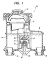
- Fig. 1 shows one example of a reservoir tank mounted on a master cylinder of a brake device, and the relation between the reservoir tank and a switch unit will now be described.
- a brake liquid 32 is stored in the reservoir tank 30, and this brake liquid is supplied to the master cylinder (not shown).
- the reservoir tank 30 is mounted on the master cylinder through rubber packings 33 (shown at a lower portion of Fig. 1) .
- a fixing screw (not shown) is inserted into a fixing hole 35, and fixedly connects the reservoir tank 30 to the master cylinder.
- a lid 34 closes an upper opening 31 of the reservoir tank 30, thereby preventing the outflow and evaporation of the brake liquid 32.
- a float 36 is received in a float receiving portion 37 provided within the reservoir tank 30 at a central portion thereof.
- the float 36 is made of a foamed resin having buoyancy relative to the brake liquid 32.
- This float 36 moves upward and downward (as indicated by an arrow in Fig. 1) in the float receiving portion 37 in accordance with the upward and downward movement of a liquid level of the brake liquid 32.
- a magnet 38 is installed in this float 36.
- a unit receiving hole 40 for receiving a reed switch unit 42 is formed at a lower side of the float receiving portion 37, and is isolated from the brake liquid 32, and is in communication with the exterior of the reservoir tank 30.
- the reed switch unit 42 received in the unit receiving hole 40, and the float 36 jointly function as a liquid level detection sensor for detecting the liquid level of the brake liquid 32 in the reservoir tank 30.
- the liquid level detection sensor operates such that a reed switch 11 mounted on the reed switch unit 42 detects magnetic flux of the magnet 38 installed in the float 36 in accordance with the upward and downward movement of the float 36.
- the magnet 38 approaches the reed switch 11, so that a contact portion of the reed switch 11 is closed, thereby detecting the fall of the liquid level of the brake liquid 32.
- Fig. 5 is a cross-sectional view of the reed switch unit taken along the line D-D of Fig. 3.
- the reed switch unit 44 of this embodiment comprises a reed switch 11, similar to the reed switch of the above-mentioned conventional construction, and a unit main body 45 made of a synthetic resin.
- a right portion of the unit main body 45 is formed into a connector portion 45a connectable to other electrical circuit, whereas a left portion thereof is formed into a mounting portion 45b on which the reed switch 11 is mounted.
- Terminals 50 and 50 are provided at predetermined portions of the mounting portion 45b, respectively. Reed portions 18 and 18 are fixedly connected respectively to the terminals 50 and 50 to thereby mount the reed switch 11 on the unit main body 45.
- the terminals 50 and 50 are constructed by metal members, respectively, which are formed integrally respectively with connection terminals 23 and 23 provided within the connector portion 45a.
- Each of the terminals 50 includes a mounting portion 52, on which the reed portion 18 is adapted to mount, and a bent piece portion 54 which is formed integrally with the mounting portion 52 and is bent to oppose to the mounting portion 52 so that the reed portion 18 can be held between the mounting portion 52 and the bent piece portion 54.
- the bent piece portion 54 and the mounting portion 52 jointly assume a generally U-shape or V-shape as viewed from the front side thereof (Fig. 6).
- each reed portion 18 is fitted into the corresponding terminal 50 through an open side 57 thereof between the bent piece portion 54 and the mounting portion 52, and is pressed against an interconnecting portion 55 (defining the bottom of the V- or U-shaped body), interconnecting the bent piece portion 54 and the mounting portion 52, thereby performing the positioning of the reed switch 11 in a direction of the width thereof (that is, in a direction of arrow A in Figs. 3 and 6).
- the positioning of the reed switch 11 in a direction of the height thereof is determined at the time when the reed portions 18 are put on the mounting portions 52, respectively.
- the term "radial direction of the reed switch” means a concept including both the direction of the width and the direction of the height. In the specification, this term will hereafter be explained based on this concept.
- a stopper wall 56 is formed on the mounting portion 45b disposed between the connector portion 45a and the terminal 50 close to the connector portion 45a so as to project upwardly (see Fig. 4).
- the stopper wall 56 is formed integrally with the unit main body 45.
- the stopper wall 56 is provided for performing the positioning of the reed switch 11 in the direction of the axis thereof (that is, in a direction of arrow B in Figs. 3 and 4) when mounting the reed switch 11 on the unit main body 45. Namely, when mounting the reed switch 11 on the unit main body 45, the distal end of the reed portion 18, disposed close to the connector portion, is abutted against the stopper wall 56, thereby performing the positioning of the reed switch 11 in the axial direction.
- the bent piece portion 54 of each terminal 50 is bent to completely close the open side 57, and at the same time fusing (fusion bonding by heat) is applied.
- the reed switch 11 is completely fixed to the unit main body 45 by this fusing operation.
- the fixing of the reed portion 18 to the terminal 50 can be performed by resistance welding such as spot welding and projection welding instead of using the above fusing operation. With such resistance welding, the physical fixing and the electrical connection can both be performed positively.
- the fixing of the reed portion 18 to the terminal 50 may be performed by soldering.
- any member of the unit main body 45 does not contact with the glass tube 16.
- the reed switch 11 is fixed in such a manner that the glass tube 16 is spaced from the unit main body 45, with a gap 59 (Figs. 4 and 5) formed between the glass tube 16 and the mounting portion 45b of the unit main body 45. Therefore, even when the reservoir tank receiving the reed switch unit 44 is mounted on a vehicle, stresses due to vibrations and thermal expansion and contraction will not develop in the glass tube 16, and therefore the glass tube 16 can be prevented from damage and so on.
- the mounting position is determined using the reed portions 18 instead of using the glass tube 16 as a reference, and therefore the glass tube 16 will not contact any portion, and the mounting operation can be carried out in such a manner that any stress will not develop in the glass tube 16, and also the accurate positioning can be achieved, and therefore variations in the detection of the liquid level in the reservoir tank can be suppressed.
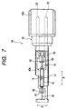
- each of the terminals 60 has the same construction as described above for the conventional structure, and has a slit 62 for interposing the reed portion 18.
- each of the terminals 60 has the slit 62 for interposing the reed portion 18, also, any member, which is in contact with the glass tube 16 of the reed switch 11, is not provided on the unit main body 45 so that the glass tube 16 will not contact such a member.
- the reed switch 11 is fixed in such a manner that the glass tube 16 is spaced from the unit main body 45, with a gap formed between the glass tube 16 and the mounting portion 45b of the unit main body 45.
- the position of the reed portion 18 in a direction of the width is determined when the reed portion 18 is fitted into the slit 62, and the position of the reed portion 18 in a direction of the height is determined when the reed portion 18 is pushed to the bottom of the slit 62.
- the positioning of the reed switch 11 in an axial direction is performed by abutting the end of the reed portion 18 against the stopper wall 56 to thereby regulate the movement in the axial direction (that is, in a direction of arrow B).
- this reed switch unit 64 the positioning of the reed switch 11 can be effected without using the glass tube 16 as a reference, and therefore the glass tube 16 will not contact any portion, and any stress will not develop in the glass tube 16, thus preventing the glass tube 16 from damage and so on, and also the accurate positioning can be achieved, and therefore variations in the detection of the liquid level in the reservoir tank can be suppressed.
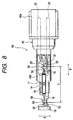
- each of reed portions 18 of a reed switch 11 is not straight, but is bent at a predetermined portion thereof.
- Terminals 50 of this reed switch unit 68 have the same shape as that of the terminals 50 of the reed switch unit 44 shown in Figs. 3 to 6, but a unit main body 45 of this reed switch unit 68 differs from the unit main body 45 of the reed switch unit 44 in that any stopper wall 56 is not provided.
- the reed portion 18 is bent at a portion 19 thereof to be fixed to the terminal 50.
- the portion 19 to be fixed to the terminal 50 is so bent that a distal end portion 25 of the reed portion 18 is directed toward an interconnecting portion 55 (see Fig. 6) of the terminal 50 (disposed in the direction of the width (i.e., a direction of arrow A)), interconnecting a bent piece portion 54 and a mounting portion 52.
- the reed portion 18 is thus bent at its portion 19 to be fixed to the terminal 50 in such a manner that the distal end portion is directed toward the interconnecting portion 55 of the terminal 50. Therefore, the distal end portion 25 of the reed portion 18, extending from the bent portion 19, is abutted against the interconnecting portion 55 of the terminal 50, thereby regulating the movement of the reed portion in the axial direction.
- the positioning of the reed switch in the axial direction can be performed through the distal end portions 25 and 25 of the two reed portions 18 which regulate the axial movements of these reed portions, respectively.
- the positioning of the reed switch in the direction of the width is performed by fitting each reed portion 18 into the corresponding terminal 50 through the open side 57 thereof and then by pressingly abutting the reed portion 18 against the interconnecting portion 55 interconnecting the bent piece portion 54 and the mounting portion 52 (Fig. 6), as described above for the first embodiment.
- the positioning of the reed switch in the direction of the height is performed at the time when the reed portions 18 are mounted on the mounting portions 52, respectively, as described above for the first embodiment.
- a glass tube 16 is fixed in such a manner that it does not contact any portion of the unit main body 45, and besides the positioning of the reed switch 11 can be performed without using the glass tube 16 as a reference.
- the terminals may be replaced by such terminals as described above for the conventional construction and the embodiment of Fig. 7, each of such terminals (Fig. 9) having a slit 62 for interposing the reed portion 18.
- a portion 19 of each reed portion 18 to be fixed to the terminal 60 in an interposed manner is bent in a direction of the width (that is, in a direction of arrow A) .
- a distal end portion 25 of the reed portion 18 extending from the bent portion 19 may be directed toward either side of the widthwise direction.
- this reed switch unit 70 also, when mounting the reed switch 11 on the unit main body 45, the positioning of the reed switch in the axial direction (that is, in a direction of arrow B) can be performed through the bent portions 19 of the reed portions 18 which abut respectively against the terminals 60 to thereby regulate the movement of the reed switch 11.
- the positioning of the reed switch in the direction of the width is performed merely by fitting each reed portion 18 into the slit 62 in the corresponding terminal 60 since the movement of the reed portion 18 in the slit 62 is regulated in the direction of the diameter.
- the positioning of the reed switch in the direction of the height is performed at the time when each reed portion 18 fitted into the slit 62, and is pressed against the bottom of the slit 62, as described above for the first embodiment.
- a glass tube 16 is fixed in such a manner that it does not contact any portion of the unit main body 45, and besides the positioning of the reed switch 11 can be effected without using the glass tube 16.
- the two reed portions 18 are first fitted respectively into the two terminals 50 (or 60), and then the reed switch 11 is moved in the axial direction so as to abut the distal end portion of the reed portion 18, extending from the bent portion 19, against the corresponding terminal 50 (or 60).
- the axial movement of the reed switch is regulated, thus performing the positioning of the reed switch in the axial direction.
- the positioning in the direction of the width and the positioning in the direction of the height are performed when each reed portion is fitted into the terminal 50 (or 60) since the movement of the reed portion is regulated, as described above.
- the reed switch unit of the invention comprises the reed switch, including the contact portion, sealed in the glass tube, and the reed portions extending respectively from the opposite ends of the glass tube in the direction of the axis thereof, and the unit main body including the terminals which support the reed portions, respectively, in electrically-connected relation thereto to fix the reed switch, and the reed switch is fixed to the unit main body in such a manner that the glass tube is disposed in non-contact relation to the unit main body. Therefore, even when the reservoir tank, containing the reed switch unit, is mounted on a vehicle, stresses due to vibrations and thermal expansion and contraction will not develop in the glass tube, thus preventing the glass tube from damage and so on.
- the position of mounting of the reed switch on the unit main body is set by determining the positions of the reed portions, and therefore the positioning, which has heretofore been effected using the glass tube, does not need to be carried out. Therefore, the inaccurate positioning by the use of the glass tube, subjected to dimensional variations, is thus eliminated, and therefore variations in the detection of the liquid level in the reservoir tank can be suppressed. And besides, there is not provided any portion for contact with the glass tube serving as a positioning reference, and therefore any stress will not develop in the glass tube, thus preventing the glass tube from damage and so on.
Landscapes
- Switches That Are Operated By Magnetic Or Electric Fields (AREA)
- Level Indicators Using A Float (AREA)
- Transmission Of Braking Force In Braking Systems (AREA)
- Switches Operated By Changes In Physical Conditions (AREA)
Abstract
Description
Claims (12)
- A reed switch unit for detecting a liquid level of a reservoir tank of a master cylinder, comprising:a reed switch including a glass tube, and a pair of reed portions extending respectively from opposite ends of said glass tube in a direction of an axis thereof, said pair of reed portions cooperatively defining a contact portion sealed in said glass tube; anda unit main body including terminals respectively supporting said reed portions to be electrically connectable,
wherein said reed switch is fixed to said unit main body in such a manner that said glass tube is disposed apart from said unit main body. - A reed switch unit according to claim 1, wherein said reed portions are respectively fixed to said terminals by resistance welding.
- A reed switch unit for detecting a liquid level of a reservoir tank of a master cylinder, comprising:a reed switch including a glass tube, and a pair of reed portions extending respectively from opposite ends of said glass tube in a direction of an axis thereof, said pair of reed portions cooperatively defining a contact portion sealed in said glass tube; anda unit main body including terminals respectively supporting said reed portions to be electrically connectable, to thereby fix said reed switch;
wherein the mounting position of said reed switch on said unit main body is set by determining the positions of said reed portions. - The reed switch unit according to claim 3, wherein said unit main body includes a stopper wall abuttable against one end of one of said reed portions for regulating the mounting position of said reed switch in the axial direction, andsaid terminal includes an interposing portion at least partially surrounding an outer periphery of said reed portion for regulating the mounting position of said reed switch in a redial direction.
- The reed switch unit according to claim 4, wherein said interposing portion is constructed by a slit interposing said reed portion.
- The reed switch unit according to claim 4, wherein said interposing portion is constructed by a mounting portion of said unit main body, and a bent piece portion extending from said mounting portion and interposing said reed portion in cooperation with said mounting portion.
- The reed switch unit according to claim 3, wherein said reed portions includes a bent portion to be bent at a fixed position of said terminal; andsaid bent portion is abutted against said terminal to regulate the mounting position of said reed switch.
- A reed switch unit according to claim 3, wherein said reed portions are respectively fixed to said terminals by resistance welding.
- A assembling method of a reed switch unit for detecting a liquid level of a reservoir tank of a master cylinder, said method comprising the steps of:using a reed switch formed such that a pair of reed portions extend respectively from opposite ends of a glass tube in a direction of an axis thereof; andfixing said pair of reed portions to a pair of terminals of a unit main body such that said glass tube is disposed apart from said unit main body.
- The assembling method according to claim 9, wherein said reed switch is simultaneously positioned into said unit main body by fixing said pair of reed portions to said pair of terminals.
- The assembling method according to claim 9, wherein said reed portions are fixed to said terminals after a one end of one of said reed portions is abutted against a stopper of said unit main body, which is located in the axial direction of said reed switch.
- The assembling method according to claim 9, wherein said reed portions are respectively fixed to said terminal by resistance welding.
Applications Claiming Priority (4)
| Application Number | Priority Date | Filing Date | Title |
|---|---|---|---|
| JP20421099 | 1999-07-19 | ||
| JP20421099 | 1999-07-19 | ||
| JP2000064489A JP4088399B2 (en) | 1999-07-19 | 2000-03-09 | Reed switch unit |
| JP2000064489 | 2000-03-09 |
Publications (3)
| Publication Number | Publication Date |
|---|---|
| EP1071107A2 true EP1071107A2 (en) | 2001-01-24 |
| EP1071107A3 EP1071107A3 (en) | 2002-09-11 |
| EP1071107B1 EP1071107B1 (en) | 2006-02-15 |
Family
ID=26514342
Family Applications (1)
| Application Number | Title | Priority Date | Filing Date |
|---|---|---|---|
| EP00114961A Expired - Lifetime EP1071107B1 (en) | 1999-07-19 | 2000-07-19 | Reed switch unit |
Country Status (5)
| Country | Link |
|---|---|
| US (1) | US6476699B1 (en) |
| EP (1) | EP1071107B1 (en) |
| JP (1) | JP4088399B2 (en) |
| DE (1) | DE60025977T2 (en) |
| TW (1) | TW466193B (en) |
Cited By (1)
| Publication number | Priority date | Publication date | Assignee | Title |
|---|---|---|---|---|
| ITFI20080235A1 (en) * | 2008-12-04 | 2010-06-05 | Enrico Raddi | "A REGULATOR GROUP TO PILOT A POWER PUMP OF A LOCAL DISTRIBUTION NETWORK OF A LIQUID" |
Families Citing this family (3)
| Publication number | Priority date | Publication date | Assignee | Title |
|---|---|---|---|---|
| CN1299181C (en) * | 2004-04-02 | 2007-02-07 | 郭铨开 | Pneumatic water level controller |
| US7360529B2 (en) * | 2004-10-29 | 2008-04-22 | American Power Conversion Corporation | Fuel level measurement and run time interpolation |
| CN114910139B (en) * | 2022-04-14 | 2026-04-07 | 应急管理部研究中心 | An energy-saving monitoring and early warning system for urban flood-prone areas |
Family Cites Families (12)
| Publication number | Priority date | Publication date | Assignee | Title |
|---|---|---|---|---|
| JPS5699080A (en) * | 1980-01-11 | 1981-08-10 | Nec Corp | Resistance welder |
| US4516101A (en) * | 1983-05-02 | 1985-05-07 | Tohoku Metal Industries, Ltd. | Air-flow-rate sensors |
| JPH079101Y2 (en) * | 1988-08-10 | 1995-03-06 | 矢崎総業株式会社 | Reed switch mounting structure for eddy current indicator |
| US5019795A (en) * | 1989-12-06 | 1991-05-28 | Molex Incorporated | Splice block for security system switch |
| US5026305A (en) * | 1990-06-28 | 1991-06-25 | Amp Incorporated | Connector for reed switch or similar electrical component |
| JPH0718381U (en) * | 1993-09-06 | 1995-03-31 | 住友電装株式会社 | connector |
| JP3428717B2 (en) | 1994-02-07 | 2003-07-22 | 住友電装株式会社 | Electrical connector |
| JPH07335278A (en) * | 1994-06-13 | 1995-12-22 | Kansei Corp | Terminal connecting structure |
| US5770792A (en) * | 1995-10-27 | 1998-06-23 | Nippon Aleph Corporation | Shock sensors |
| IT1284455B1 (en) | 1996-06-28 | 1998-05-21 | Fitre S P A | FLOAT LEVEL SENSOR |
| US5827962A (en) | 1996-09-12 | 1998-10-27 | Itt Automotive Inc. | Hydraulic brake fluid reservoir level indicator system |
| DE19720601C1 (en) * | 1997-05-16 | 1998-10-15 | Robert Seuffer Gmbh & Co | Reed relay switching device with tuning facility |
-
2000
- 2000-03-09 JP JP2000064489A patent/JP4088399B2/en not_active Expired - Lifetime
- 2000-07-13 US US09/615,943 patent/US6476699B1/en not_active Expired - Lifetime
- 2000-07-14 TW TW089114100A patent/TW466193B/en not_active IP Right Cessation
- 2000-07-19 EP EP00114961A patent/EP1071107B1/en not_active Expired - Lifetime
- 2000-07-19 DE DE60025977T patent/DE60025977T2/en not_active Expired - Lifetime
Cited By (1)
| Publication number | Priority date | Publication date | Assignee | Title |
|---|---|---|---|---|
| ITFI20080235A1 (en) * | 2008-12-04 | 2010-06-05 | Enrico Raddi | "A REGULATOR GROUP TO PILOT A POWER PUMP OF A LOCAL DISTRIBUTION NETWORK OF A LIQUID" |
Also Published As
| Publication number | Publication date |
|---|---|
| TW466193B (en) | 2001-12-01 |
| DE60025977T2 (en) | 2006-10-26 |
| DE60025977D1 (en) | 2006-04-20 |
| US6476699B1 (en) | 2002-11-05 |
| EP1071107B1 (en) | 2006-02-15 |
| JP4088399B2 (en) | 2008-05-21 |
| EP1071107A3 (en) | 2002-09-11 |
| JP2001091340A (en) | 2001-04-06 |
Similar Documents
| Publication | Publication Date | Title |
|---|---|---|
| US4557144A (en) | Electric level sensor for motor vehicle fuel tanks | |
| EP1174692B1 (en) | Liquid level detector | |
| JP2008510110A (en) | Ball joints for cars | |
| US20030110652A1 (en) | Electrolytic tilt-sensor | |
| EP0372909B1 (en) | Master cylinder hydraulic reservoirs | |
| JP4118990B2 (en) | Pressure sensor | |
| EP1071107B1 (en) | Reed switch unit | |
| KR100542869B1 (en) | Photo Interrupter | |
| GB2281822A (en) | Sealingly connecting an electrical component | |
| US5917402A (en) | Mounting structure for mounting an insulating substrate having a resistor pattern onto a holder | |
| CN100430683C (en) | Passive magnetic position sensor and method of mounting a passive magnetic position sensor | |
| US7251999B2 (en) | Level sensor for a fuel tank | |
| US10788353B2 (en) | Liquid-surface detection device | |
| JP2001035329A (en) | Reed switch unit and reed switch mounting method | |
| GB2217111A (en) | A transducer | |
| JP4084504B2 (en) | Reed switch unit | |
| EP1040977B1 (en) | Switch unit | |
| JP2603344Y2 (en) | Impact sensor | |
| JPH05215592A (en) | Liquid surface detection device | |
| JP2549099Y2 (en) | Liquid level detector for vehicles | |
| EP3628540B1 (en) | Windshield sensing device | |
| JPH0316040Y2 (en) | ||
| JP2515121Y2 (en) | Temperature sensor | |
| JP2505560Y2 (en) | High voltage resistance pack | |
| JP2004286479A (en) | Liquid level detector |
Legal Events
| Date | Code | Title | Description |
|---|---|---|---|
| PUAI | Public reference made under article 153(3) epc to a published international application that has entered the european phase |
Free format text: ORIGINAL CODE: 0009012 |
|
| AK | Designated contracting states |
Kind code of ref document: A2 Designated state(s): AT BE CH CY DE DK ES FI FR GB GR IE IT LI LU MC NL PT SE |
|
| AX | Request for extension of the european patent |
Free format text: AL;LT;LV;MK;RO;SI |
|
| PUAL | Search report despatched |
Free format text: ORIGINAL CODE: 0009013 |
|
| AK | Designated contracting states |
Kind code of ref document: A3 Designated state(s): AT BE CH CY DE DK ES FI FR GB GR IE IT LI LU MC NL PT SE |
|
| AX | Request for extension of the european patent |
Free format text: AL;LT;LV;MK;RO;SI |
|
| 17P | Request for examination filed |
Effective date: 20021011 |
|
| AKX | Designation fees paid |
Designated state(s): DE GB |
|
| 17Q | First examination report despatched |
Effective date: 20040728 |
|
| GRAP | Despatch of communication of intention to grant a patent |
Free format text: ORIGINAL CODE: EPIDOSNIGR1 |
|
| GRAS | Grant fee paid |
Free format text: ORIGINAL CODE: EPIDOSNIGR3 |
|
| GRAA | (expected) grant |
Free format text: ORIGINAL CODE: 0009210 |
|
| RIN1 | Information on inventor provided before grant (corrected) |
Inventor name: AMANO, TSUTOMU,C/O NISSIN KOGYO CO., LTD. Inventor name: OTA, KAZUHIRO,C/O NISSIN KOGYO CO., LTD. |
|
| AK | Designated contracting states |
Kind code of ref document: B1 Designated state(s): DE GB |
|
| REG | Reference to a national code |
Ref country code: GB Ref legal event code: FG4D |
|
| REF | Corresponds to: |
Ref document number: 60025977 Country of ref document: DE Date of ref document: 20060420 Kind code of ref document: P |
|
| PLBE | No opposition filed within time limit |
Free format text: ORIGINAL CODE: 0009261 |
|
| STAA | Information on the status of an ep patent application or granted ep patent |
Free format text: STATUS: NO OPPOSITION FILED WITHIN TIME LIMIT |
|
| 26N | No opposition filed |
Effective date: 20061116 |
|
| REG | Reference to a national code |
Ref country code: DE Ref legal event code: R082 Ref document number: 60025977 Country of ref document: DE Representative=s name: HOFFMANN - EITLE PATENT- UND RECHTSANWAELTE PA, DE Ref country code: DE Ref legal event code: R081 Ref document number: 60025977 Country of ref document: DE Owner name: AUTOLIV NISSIN BRAKE SYSTEMS JAPAN CO., LTD., , JP Free format text: FORMER OWNER: NISSIN KOGYO CO., LTD., UEDA, NAGANO, JP |
|
| REG | Reference to a national code |
Ref country code: GB Ref legal event code: 732E Free format text: REGISTERED BETWEEN 20160811 AND 20160817 |
|
| PGFP | Annual fee paid to national office [announced via postgrant information from national office to epo] |
Ref country code: DE Payment date: 20190730 Year of fee payment: 20 |
|
| PGFP | Annual fee paid to national office [announced via postgrant information from national office to epo] |
Ref country code: GB Payment date: 20190730 Year of fee payment: 20 |
|
| REG | Reference to a national code |
Ref country code: DE Ref legal event code: R071 Ref document number: 60025977 Country of ref document: DE |
|
| REG | Reference to a national code |
Ref country code: GB Ref legal event code: PE20 Expiry date: 20200718 |
|
| PG25 | Lapsed in a contracting state [announced via postgrant information from national office to epo] |
Ref country code: GB Free format text: LAPSE BECAUSE OF EXPIRATION OF PROTECTION Effective date: 20200718 |