-
The present invention relates to a device and a process for displaying an image
representing an object in three dimensions on a screen according to a perspective that
depends on the user's position.
-
US Patent 5,367,614 describes a system that enables an image in three
dimensions to be displayed with variable perspective. The perspective varies according
to movements of the user's head. This device is used to represent an object so that the
user looks at it as he/she were looking at a real object and not an object represented on a
screen. The system utilized comprises an ultrasound transmitter intended to be put on
the user's head and to emit sound waves, and one or more receivers intended to be
arranged on the screen and to receive these waves. The transmitter and receiver are
connected to an interface intended to analyze the signals and especially to calculate the
time between the moment when the sound wave is emitted and the moment when it is
received.
-
Such a device can easily be influenced by the user's external environment, i.e.
the receiver receives sound waves coming from other sound sources than the transmitter.
In addition, such a device has to be worn by the user, which is not very practical.
-
An object of the invention is to provide a device and a process intended to give
the impression to a user who is looking at an object in three dimensions on a screen of
looking at a real object, which do not have the disadvantages of the background art.
-
The present invention relates to a device for displaying an image of an object
according to a perspective that depends on the position of a user looking at the image,
the device comprising:
- a screen intended for displaying the image;
- a means for detecting the position of the user which comprises at least one
recording system intended to record the user's image and a means for processing the
recorded data so as to determine the variation of the user's position in relation to the
screen; and
- a means for generating an image of the object according to a perspective that
depends on the user's position so that the image of the object is modified when the user
moves in front of the screen.
-
-
The present invention also relates to a device for displaying an image of an object
according to a perspective that depends on the position of a user looking at the image,
the device comprising:
- a screen intended for displaying the image;
- at least one recording system intended to record the user's image;
- a processor for processing the recorded data so as to determine the variation of
the user's position in relation to the screen; and
- a processor for generating an image of the object according to a perspective that
depends on the user's position so that the image of the object is modified when the user
moves in front of the screen.
-
-
The present invention also relates to a process for displaying an image of an
object according to a perspective that depends on the position of a user looking at the
image, the process comprising the steps of:
- displaying the image of the object on a screen;
- recording at least one image of the user by means of a recording system;
- determining the variation in the user's position in relation to the screen; and
- utilizing an algorithm to enable the image of the object displayed on the screen to
be modified according to the variation of the user's position in relation to the screen.
-
-
Other characteristics will appear on reading the description below, with reference
to the drawings wherein:
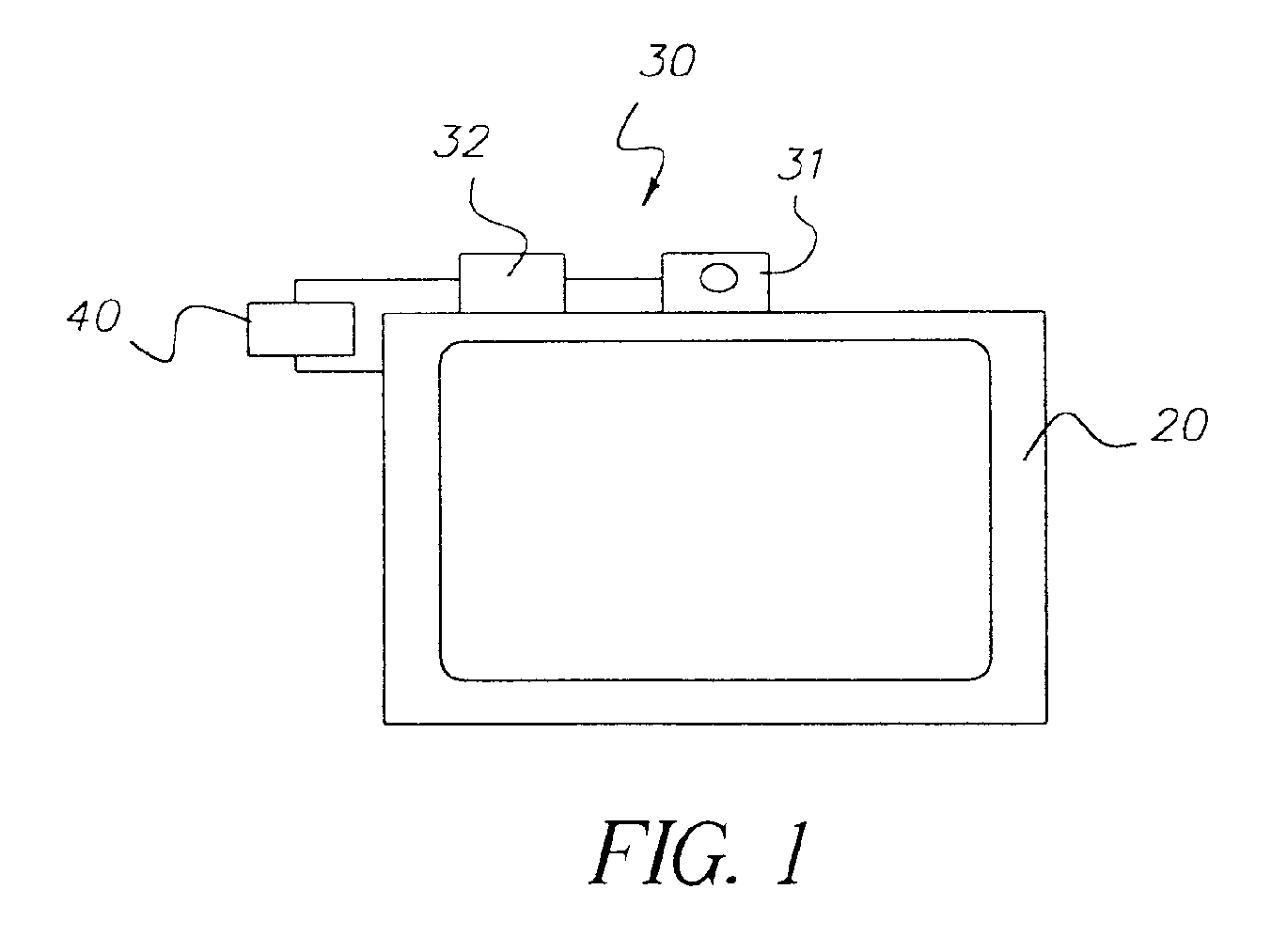
- Figure 1 represents a diagrammatic view of a first embodiment of the device
according to the invention;
- Figure 2 represents a top view of the first embodiment of the invention device;
- Figure 3 represents an image of the user recorded by the first embodiment of the
invention device;
- Figure 4 represents a perspective view of the first embodiment of the invention
device;
- Figure 5 represents a diagrammatic view of a second embodiment of the invention
device;
- Figure 6 represents a top view of the second embodiment of the invention device;
and
- Figures 7a and 7b represent images of the user recorded by the second
embodiment of the invention device.
-
-
The invention device is intended for displaying an image of an object on a screen
according to a perspective that depends on the position of the user who is looking at the
image.
-
With reference to Figures 1 and 5, it can be seen diagrammatically that the device
comprises a screen 20 on which an object is displayed. The user 10 of the device is
placed opposite the screen 20 so as to look at the object. In order to give the impression
to the user 10 that he/she is looking at a real object, the device of the present invention
proposes to modify the perspective by which the object is displayed on the screen 20
according to the user's position 10 in relation to the screen 20. Hence the device
comprises a means 30 for detecting the user's position 10 and in particular the position of
the user's face 10. The means 30 for detecting the user's position 10 comprises at least
one recording system 31 intended to record continuously and digitally the image of the
user's face 10. This is for instance a digital camera, e.g. a KODAK DVC 323 camera.
The device also comprises a means 32 for processing the data recorded by the camera 31
so as to determine the user's position 10 in relation to the screen 20. As the user's
image 10 is recorded continuously, the means 32 for processing the recorded data
enables the user's position 10 in relation to a reference position to be determined at any
time. When the position is determined, data is generated according to which a means 40
for generating an image of the object will modify the image of the object.
-
The invention process comprises the following steps. After having initialized the
system the image of the object is displayed on the screen 20. By means of at least one
recording system 31 an image of the user 10 is recorded. Then the variation of the
user's position 10 in relation to the screen 20 is determined. Then an algorithm is
utilized that enables the image of the object displayed on the screen 20 to be modified
according to the variation of the user's position 10 in relation to the screen 20. To
determine the variation of the user's position 10 in relation to the screen 20 several
embodiments are proposed. First variations of angular position can be determined in a
horizontal and/or vertical plane. Also, independently or in addition, variations of
distance between the user 10 and the screen 20 can be determined.
-
According to a first embodiment illustrated diagrammatically in Figure 1, the
device comprises a single recording system 31. This is a digital camera arranged for
instance centrally on top of the display screen 20. Clearly the camera can be placed in
any other location that enables the image of the user's face 10 to be recorded. The face
is recorded in one direction. To determine angular variations of the user 10 in relation
to the screen 20, the means 32 for processing the data is a means for registering a
characteristic point of the user 10, preferably on his/her face. For example the following
can be selected: the nose, the center between the two eyes, or the barycenter of the flesh
tints of the face. Any recognition process known to those skilled in the art can be
utilized for this purpose. According to a particular embodiment, the position of the two
points corresponding to the eyes is determined. At the start of utilization, the image of
the user's face 10 recorded by the camera 31 is displayed on the screen 20. At this
moment the user 10 is invited to initialize the system, for instance by generating one or
more pulses. For example it can be envisaged that the user 10 clicks on the two points
corresponding to the eyes. At the same time as he/she initializes the system, the two
points are thus registered in a system of coordinates attached to the image recorded by
the camera 31 as illustrated in Figure 3. Thus two couples (X1, Y1) and (X2, Y2) are
obtained. By calculating the coordinates of the couple [(X1 +X2)/2; (Y1 +Y2)/2], the
coordinates of the center between the two eyes are determined. Then the axis d1 between
the characteristic point of the user's face 10 and the center of the camera 31 is
determined. A value α is then attributed to the angle, measured in a horizontal plane,
between this axis d1 and the camera's optical axis as illustrated in Figure 2.
Advantageously, a value β is attributed to the angle, measured in a vertical plane,
between this axis d1 and the camera's optical axis as illustrated in Figure 4. When for
instance the user moves his/her head in a horizontal and/or vertical plane, the
coordinates of the couple [(X1 +X2)/2; (Y1 +Y2)/2] vary so that the angle α and/or β
varies. An algorithm is then utilized to modify the image of the object to be looked at
on the screen 20 according to the variation of the angle α and/or β so as to rotate the
object by a certain angle, i.e. to represent the object according to a given perspective.
Advantageously, to simulate reality approximately, two points separated by a known
mean distance can be registered, e.g. the distance between the two eyes. From this
distance, the user's position on the axis d1 is determined. Also knowing the position of
the camera 31 in relation to the center of the screen, the approximately actual angles of
variations of the user in relation to the screen can be deduced. Thus, the object can be
rotated by this actual variation of angle so that reality is simulated. The object can also
be moved by twice the angle or by another proportion.
-
According to this embodiment, advantageously in addition, the variations of
distance between the user 10 and the screen 20 are determined. Therefore, two
characteristic points of the user's image 10 are determined and the variation of the
distance between these two points, e.g. the two eyes, is registered. For instance when
the user 10 initializes the system, an arbitrary value A can be attributed to the distance
between the user 10 and the screen 20. In reality this reference value is attributed to the
distance between the two eyes (X2-X1, Y2-Y1) according to our example as illustrated in
Figure 3. Thus, when for instance, the user 10 approaches or retreats from the screen
20, the distance between the two points measured will increase or decrease in relation to
the reference value. According to the variation of this distance, an algorithm is utilized
to enable the displayed object to be modified so that it is displayed by being enlarged or
reduced. Clearly any distance between two characteristic points of the face can be
utilized to register the variation of distance between the screen 20 and the user 10.
-
According to this embodiment, when the user 10 only rotates his/her head in a
plane parallel to the screen, the object is not modified. In fact, the distance (X2-X1, Y2-Y1)
between the two eyes is not modified. Similarly the angles α and β are practically
not modified because the whole head is not moved.
-
According to a second embodiment illustrated diagrammatically in Figure 5, the
device comprises two recording systems 31. These are two digital cameras arranged for
instance on top of the screen 20 and oriented at two different angles so as to record two
different images of the user 10. Before an image is recorded, the user 10 is invited to
initialize the device, for instance by generating a pulse. At this moment, each recording
system 31 then records one image of the user's face 10 as illustrated in Figures 7a and
7b.
-
In order to register the variations of the user's position 10, the means 32 for
processing the data is for example a means for registering a characteristic point of the
user 10, preferably his/her face in the two recordings. For instance the flesh tints of the
face can be registered, and the barycenter of the face calculated. To that end, the value of
each pixel representing flesh tints is taken as one. The coordinates of these pixels are added
to each other and divided by the number of pixel representing flesh tints. Thus the
coordinates (X3, Y3) and (X4, Y4) of the barycenter are obtained in the system of
coordinates associated with each image as illustrated in Figures 7a and 7b. Then the
axes d2 and d3 between each recording system 31 are determined and the barycenter of
the flesh tints of the user's face 10 as illustrated in Figure 6. Knowing the position of
each recording system 31, one in relation to the other and in relation to the screen 20,
the exact position in space of the intersection I between the axes d2 and d3 in relation to
the center of the screen is deduced. When the user 10 moves his/her head in a horizontal
and/or vertical plane, the coordinates (X3, Y3) and (X4, Y4) of the barycenter vary which
causes a variation of the position of the intersection I between the axes d2 and d3. An
algorithm is then utilized to modify the image of the object so as to rotate the object by a
certain angle corresponding to the user's actual angular variation in relation to the screen
so that reality is simulated, or again by another proportion.
-
According to this embodiment, the variation of the distance between the user and
the screen is directly determined by the variation of the position of the intersection I
between the two axes d2 and d3. Thus, when the user 10 approaches or retreats from the
screen 20, the coordinates (X3, Y3) and (X4, Y4) of the barycenter are modified so that
the intersection I is no longer at the same distance from the screen 20. According to the
variation of this distance, a new image of the object is generated so that the object
appears enlarged or reduced for the user 10. Clearly any characteristic point of the face
can be utilized in this embodiment.
-
Here again, when the user 10 only rotates his/her head in a plane parallel to the
screen, the object is not modified. In fact, the barycenter of the flesh tints does not
vary.
-
The device that has been described above is for instance utilized on an interactive
terminal that enables the user to be given the illusion of looking at real objects, which
are in fact objects displayed on a screen. This device can also be utilized for simulation,
for example flight simulation or any other activity.