EP1071001A2 - Barcodeleser-Adressierung - Google Patents
Barcodeleser-Adressierung Download PDFInfo
- Publication number
- EP1071001A2 EP1071001A2 EP00114470A EP00114470A EP1071001A2 EP 1071001 A2 EP1071001 A2 EP 1071001A2 EP 00114470 A EP00114470 A EP 00114470A EP 00114470 A EP00114470 A EP 00114470A EP 1071001 A2 EP1071001 A2 EP 1071001A2
- Authority
- EP
- European Patent Office
- Prior art keywords
- arrangement according
- barcode
- control unit
- lines
- wire lines
- Prior art date
- Legal status (The legal status is an assumption and is not a legal conclusion. Google has not performed a legal analysis and makes no representation as to the accuracy of the status listed.)
- Granted
Links
Images


Classifications
-
- G—PHYSICS
- G06—COMPUTING OR CALCULATING; COUNTING
- G06F—ELECTRIC DIGITAL DATA PROCESSING
- G06F12/00—Accessing, addressing or allocating within memory systems or architectures
- G06F12/02—Addressing or allocation; Relocation
- G06F12/06—Addressing a physical block of locations, e.g. base addressing, module addressing, memory dedication
- G06F12/0646—Configuration or reconfiguration
- G06F12/0669—Configuration or reconfiguration with decentralised address assignment
- G06F12/0676—Configuration or reconfiguration with decentralised address assignment the address being position dependent
Definitions
- the invention relates to an arrangement of barcode readers according to the Preamble of claim 1.
- the barcode readers are in this arrangement via bus lines to the control unit connected and form a bus system with it. Within this bus system the barcode readers are cyclically removed from the control unit given addresses.
- An address of a barcode reader is assigned via a connector unit on the barcode reader that is used to connect the bus lines.
- the connector units on each bar code reader each have a predetermined one Number of connection pins.
- a predefined number of these Connection pins are used to define the respective address of the concerned Barcode reader. This will be available from for addressing standing connection pins a predetermined number of connection pins over a conductive connection to a ground pin activated. Depending on which of the Connection pins are activated, is a specific address within a predetermined range of values provided for the respective barcode reader.
- the invention has for its object for an arrangement of the beginning mentioned type as simple and flexible a way of addressing create.
- the barcode readers are in one within the arrangement Row connected to the control unit and form a bus system with this.
- the address values of the barcode readers correspond to the position of the barcode readers within that row.
- the main advantage here is that the addresses in the barcode readers not by hardware coding or by means of a configuration setting software must be specified.
- Figure 1 shows an arrangement of barcode readers 1, which to a control unit 2 are connected.
- Each barcode reader 1 the structure of which is not shown in the drawings is used to read barcodes or similar contrast marks.
- the barcode reader 1 has a transmitter emitting light rays and a transmitter receiving receiving light rays.
- the broadcast and Receiving light beams are preferably guided over a deflection unit, which, for example, from a motor-driven polygon mirror wheel is formed.
- the transmitted light rays performed periodically within a predetermined angular range, whereby the Barcodes can be scanned with the transmitted light beams.
- the transmitted light beams are amplitude modulated imprinted.
- the reflected back as received light rays Receive light beams generate receive signals at the output of the receiver, which are evaluated in an evaluation unit. There will be decodes the modulated received signals, whereby the bar pattern of the relevant barcodes are reconstructed.
- Such barcode readers 1 are found in particular in industrial plants such as for example conveyor systems application. With such applications Usually a variety of barcode readers 1 used, the spatial arrangement of the barcode readers 1 and the number of barcode readers 1 may change, for example if the structure the system is changed.
- the barcode readers 1 are not independent of each other operated, but controlled by the control unit 2.
- the control unit 2 can be formed by a PLC control or the like his.
- the barcode readers 1 are connected to the control unit 2 via leads 3 connected. During the operation of the arrangement, the bar code readers 1 cyclically queried by the control unit 2 at predetermined addresses, whereupon the individual barcode readers 1 each give feedback output the leads 3 to the control unit 2.
- the entire arrangement forms a bus system based on the master-slave principle is working.
- the control unit 2 forms the master, while the barcode readers 1 form the slaves.
- the assignment of the addresses of the slaves is controlled and done by the master during an initialization phase, which takes place before the bus system is operated is carried out.
- the barcode readers 1 are in a row to the control unit 2 connected and the address values correspond to the respective positions of barcode readers 1 in the series.
- the feed lines 3 are between the control unit 2 and the barcode readers 1 are designed as two-wire lines.
- Such Two-wire lines can be used, for example, in CAN bus systems or the like be provided.
- the Two-wire lines from RS485 lines.
- the data exchange between the control unit takes place via these two-wire lines 2 and the barcode readers 1.
- connection 4 on the control unit 2 From a connection 4 on the control unit 2, the two-wire lines from the control unit 2 to a connection 4 'of a first barcode reader 1 led. From a second connection 4 '' on this barcode reader 1 the two-wire lines become a second bar code reader 1 guided. Here the two-wire lines in turn open at the first connection 4 ' on. At the second connection 4 '' of the barcode reader 1 are in turn Two-wire lines led out to the next barcode reader 1. To this All barcode readers 1 are in a row via the two-wire lines connected to the control unit 2. Each barcode reader shows 1 two connections 4 ', 4' 'for connecting the two-wire lines on.
- connections 4, 4 ', 4' 'data from the neighboring one Barcode reader or the control unit 2 read data or to this Units of data read out.
- the connections 4, 4 ', 4' 'on the control unit 2 and on the barcode readers 1 are identical.
- FIG. 2 shows a first embodiment of a circuit arrangement Barcode reader 1 for connecting the two-wire lines.
- the circuit arrangement comprises the two connections 4 ', 4' ', each with two connection pins 5, 6, and 7, 8 for connecting the two-wire lines.
- Transceiver unit 9 forming interface unit is provided, which receives the read data and outputs data on the two-wire lines.
- the transmitter / receiver unit 9 is an RS485 interface unit educated. This transmitter / receiver unit 9 is connected to a Computer unit 10 connected, which is preferably from the evaluation unit of the barcode reader 1 is formed or integrated in this.
- connection pins 5, 6 of the first connection 4 ' are directly via one Line 11, 12 connected to the transmitter / receiver unit 9.
- the connection pins 7, 8 of the second connection 4 ′′ are via lines 13, 14 and one Resistor 15 and a switch 16 led to the computer unit 10.
- the resistance 15 serves as a terminating resistor when activated via the switch 16 of the bus system.
- the lines 11 - 14 led away from the connection pins 5 - 8 are in pairs each coupled to a switch 17, 18 via a connecting line. These switches 17, 18 are preferably designed as relays and are via the computer unit 10 can be activated.
- the control unit 2 continuously Counter increments, these counter readings forming the address values which can be assigned to the individual barcode readers 1.
- the meter first takes meter reading one. This value is called Address value over the two-wire lines in the computer unit 10 of the first Barcode reader 1, which is directly connected to the control unit 2, read.
- the control unit 2 After the control unit 2 receives the feedback from the first barcode reader 1 received, the counter reading of the counter from Value one increased to value two. This value will be assigned as the new one Address value output on the two-wire lines.
- First the new one Address value is read back into the computer unit 10 of the first bar code reader. Since an address has already been assigned to this barcode reader 1 and the switches 17, 18 of the connecting lines are closed, the Address value via a connecting line and via the second connection 4 '' output on the two-wire lines and in the behind this barcode reader 1 connected next barcode reader 1 read.
- the address value to be assigned is transmitted via the transmitter / receiver unit 9 in the computer unit 10 read.
- this barcode reader 1 none Address value is stored in the computer unit 10 and consequently also the Switches 17, 18 of the connecting lines are still open, the value two as a new address value in the computer unit 10 of the second barcode reader 1 saved. Then there will be a response from this barcode reader 1 sent to the control unit 2. In addition, the switches 17, 18 closed in the connecting lines.
- the feedback from the second barcode reader 1 is in the control unit 2 the counter increased to three.
- This address value is then through the first two barcode readers 1 via the closed switches 17, 18 of the respective connecting lines to the third barcode reader 1 passed through. There the value three is saved as an address value.
- the address values can in principle also counted up by the computer units 10 of the individual barcode readers 1 become.
- the addressing largely corresponds to the so-called Daisy chain process.
- the addresses are assigned until the last one is sent to the control unit 2 connected barcode reader 1 was addressed. As can be seen from Figure 1 is the second connection in the last barcode reader 1 in the row 4 '' unoccupied. If the counter is incremented further by the control unit 2, then takes place via the second unoccupied connection of the last barcode reader 1 no more response. This is registered in the control unit 2, whereupon the last barcode reader 1 still addressed is sent a command, by means of which the terminating resistor in this bar code reading device 1 Activation of the assigned switch 16 activated via the computer unit 10 becomes.
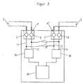
- Figure 2 shows a second embodiment of a circuit arrangement Barcode reader 1 to the bus system.
- the structure of this arrangement corresponds essentially to the circuit arrangement according to FIG. 2.
- the circuit arrangement according to FIG. 2 in this exemplary embodiment are two transceiver units 9a, 9b provided, which are each connected to the computer unit 10.
- connection pins 5, 6 of the first connection 4 ' are via the first lines 11, 12 connected to the first transmitting / receiving unit 9a.
- the connection pins 7, 8 of the second connection 4 ′′ are via the second lines 13, 14 connected to the second transmitter / receiver unit (9b).
- Between the first and second lines 11-14 run connecting lines, which in pairs a first line 11, 12 and a second line 13, 14 with each other connect.
- There is a switch in each connection line 17, 18 is provided, which can be actuated via the computer unit 10.
- switches 17, 18 are closed in the connecting lines checked in the computer unit 10 whether the output signals of the transmitting / receiving units 9a, 9b are each the same. Hereby the functionality the switches 17, 18 are checked.
- circuit arrangement can also be used according to Figure 3, an additional switchable terminating resistor, not shown be provided.
Landscapes
- Engineering & Computer Science (AREA)
- Theoretical Computer Science (AREA)
- Physics & Mathematics (AREA)
- General Engineering & Computer Science (AREA)
- General Physics & Mathematics (AREA)
- Small-Scale Networks (AREA)
- Bus Control (AREA)
- Sorting Of Articles (AREA)
Abstract
Description
- Fig. 1:
- Blockschaltbild einer Anordnung von an eine Steuereinheit angeschlossenen Barcodelesegeräten
- Fig. 2:
- Erstes Ausführungsbeispiel einer Schaltungsanordnung eines Barcodelesegeräts zum Anschluß an die Steuereinheit gemäß Figur 1.
- Fig. 3:
- Zweites Ausführungsbeispiel einer Schaltungsanordnung eines Barcodelesegeräts zum Anschluß an die Steuereinheit gemäß Figur 1.
Claims (14)
- Anordnung von Barcodelesegeräten in einem Bussystem, wobei die Barcodelesegeräte über Zuleitungen an eine Steuereinheit angeschlossen sind und von dieser jeweils unter einer Adresse abfragbar sind, dadurch gekennzeichnet, daß die Barcodelesegeräte (1) in einer Reihe an die Steuereinheit (2) angeschlossen sind, und daß die Adreßwerte der einzelnen Barcodelesegeräte (1) deren Positionen innerhalb der Reihe entsprechen.
- Anordnung nach Anspruch 1, dadurch gekennzeichnet, daß die Adressen den Barcodelesegeräten (1) während einer Initialisierungsphase zugewiesen werden.
- Anordnung nach einem der Ansprüche 1 oder 2, dadurch gekennzeichnet, daß das Bussystem nach dem Master-Slave-Prinzip arbeitet, wobei die Steuereinheit (2) den Master und die Barcodelesegeräte (1) die Slaves bilden.
- Anordnung nach einem der Ansprüche 1-4, dadurch gekennzeichnet, daß die Zuleitungen (3) von Zweidrahtleitungen gebildet sind.
- Anordnung nach Anspruch 4, dadurch gekennzeichnet, daß die Zweidrahtleitungen von RS485-Leitungen oder von Busleitungen eines CAN-Bussystems gebildet sind.
- Anordnung nach einem der Ansprüche 4 oder 5, dadurch gekennzeichnet, daß jedes Barcodelesegerät (1) jeweils einen Anschluß (4', 4'') für in das Barcodelesegerät (1) einlaufende und aus diesem ausmündende Zweidrahtleitungen aufweist.
- Anordnung nach Anspruch 6, dadurch gekennzeichnet, daß jedes Barcodelesegerät (1) wenigstens eine Sende-/Empfangseinheit (9) aufweist, welche an eine Rechnereinheit (10) angeschlossen ist, und daß die in das Barcodelesegerät (1) einlaufenden und aus diesem herausgeführten Zweidrahtleitungen über die Sende-/Empfangseinheit (9) geführt und über Schalter (17, 18) gekoppelt sind, welche über die Rechnereinheit (10) betätigbar sind.
- Anordnung nach Anspruch 7, dadurch gekennzeichnet, daß die Schalter (17, 18) von Relais gebildet sind.
- Anordnung nach Anspruch 8, dadurch gekennzeichnet, daß an den aus einem Barcodelesegerät (1) herausgeführten Zweidrahtleitungen ein Widerstand (15) mit einem Schalter (16) angeschlossen ist, welcher über die Rechnereinheit (10) betätigbar ist.
- Anordnung nach einem der Ansprüche 7 - 9, dadurch gekennzeichnet, daß jedes Barcodelesegerät (1) zwei Sende-/Empfangseinheiten (9a, 9b) aufweist, wobei die in das Barcodelesegerät (1) einlaufenden und aus diesem herausgeführten Zweidrahtleitungen jeweils an eine Sende-/Empfangseinheit (9a, 9b) angeschlossen sind.
- Anordnung nach Anspruch 10, dadurch gekennzeichnet, daß zur Kontrolle der Schalter (17, 18), die zwischen den auf die Sende-/Empfangseinheiten (9a, 9b) geführten Zweidrahtleitungen geschaltet sind, in der Rechnereinheit (10) überprüft wird, ob bei geschlossenen Schaltern (17, 18) die Ausgangssignale der Sende-/Empfangseinheiten identisch sind.
- Anordnung nach einem der Ansprüche 1-11, dadurch gekennzeichnet, daß zur Vergabe der Adressen in der Steuereinheit (2) ein Zähler fortlaufend inkrementiert wird, wobei die die Adreßwerte bildenden Zählerstände einzeln nacheinander in die Barcodelesegeräte (1) eingelesen werden.
- Anordnung nach Anspruch 12, dadurch gekennzeichnet, daß der jeweilige Adreßwert in der Rechnereinheit (10) eines Barcodelesegerätes (1) gespeichert wird, bei welcher die ein- und auslaufenden Zweidrahtleitungen durch geöffnete Schalter (17, 18) entkoppelt sind, und daß nach Abspeichern des Adreßwertes die Schalter (17, 18) über die Rechnereinheit (10) geschlossen werden.
- Anordnung nach Anspruch 13, dadurch gekennzeichnet, daß der dem Widerstand (15) zugeordnete Schalter (16) eines Barcodelesegeräts (1) über die Rechnereinheit (10) geschlossen wird, falls nach Einlesen eines Adreßwertes und Ausgabe dieses Adreßwerts über die aus diesem Barcodelesegerät herausgeführten Zweidrahtleitungen keine Rückmeldung empfangen wird.
Applications Claiming Priority (2)
| Application Number | Priority Date | Filing Date | Title |
|---|---|---|---|
| DE19931999 | 1999-07-09 | ||
| DE19931999A DE19931999B4 (de) | 1999-07-09 | 1999-07-09 | Anordnung von Barcodelesegeräten in einem Bussystem |
Publications (3)
| Publication Number | Publication Date |
|---|---|
| EP1071001A2 true EP1071001A2 (de) | 2001-01-24 |
| EP1071001A3 EP1071001A3 (de) | 2003-06-25 |
| EP1071001B1 EP1071001B1 (de) | 2004-10-27 |
Family
ID=7914185
Family Applications (1)
| Application Number | Title | Priority Date | Filing Date |
|---|---|---|---|
| EP20000114470 Expired - Lifetime EP1071001B1 (de) | 1999-07-09 | 2000-07-06 | Bussystem mit Barcodelesegeräten |
Country Status (2)
| Country | Link |
|---|---|
| EP (1) | EP1071001B1 (de) |
| DE (2) | DE19931999B4 (de) |
Cited By (2)
| Publication number | Priority date | Publication date | Assignee | Title |
|---|---|---|---|---|
| EP1445700A1 (de) | 2003-02-10 | 2004-08-11 | Delphi Technologies, Inc. | Bussystem und Verfahren zur Adresszuweisung an Peripherieeinheiten |
| WO2019007929A1 (en) | 2017-07-04 | 2019-01-10 | Gnosis S.P.A. | (SS) -ADENOSYL METHIONINE SALT WITH INOSITOL HEXAPHOSPHATE, AND PROCESS FOR PREPARING SAME |
Families Citing this family (7)
| Publication number | Priority date | Publication date | Assignee | Title |
|---|---|---|---|---|
| DE10225888B4 (de) * | 2002-06-11 | 2007-06-21 | Daimlerchrysler Ag | Modulares Fahrwerksystem |
| DE10318451A1 (de) * | 2003-04-23 | 2004-11-11 | Endress + Hauser Conducta Gesellschaft für Mess- und Regeltechnik mbH + Co.KG | Verfahren zum Adressieren von Modulen eines Bussystems |
| DE10336301A1 (de) * | 2003-07-31 | 2005-03-10 | Ego Elektro Geraetebau Gmbh | Verfahren zur dynamischen Vergabe von Adressen sowie zugehörige Verwendung für Heizeinrichtungen |
| DE102005014124A1 (de) * | 2005-03-22 | 2006-09-28 | E.G.O. Elektro-Gerätebau GmbH | Verfahren zur dynamischen Vergabe von Adressen sowie zugehörige Verwendung für Heizeinrichtungen |
| WO2009006916A1 (de) | 2007-07-06 | 2009-01-15 | Moeller Gmbh | System und verfahren zur steuerung von busvernetzten geräten über einen offenen feldbus |
| EP4054128B1 (de) * | 2021-03-01 | 2026-04-29 | Elmos Semiconductor SE | Verfahren zur initialisierung eines seriellen kommunikationsbussystems |
| FR3138537B1 (fr) * | 2022-07-28 | 2025-02-28 | Tribu Leblanc | Passerelle électronique dans un réseau comprenant un serveur d’administration et des dispositifs de contrôle |
Family Cites Families (5)
| Publication number | Priority date | Publication date | Assignee | Title |
|---|---|---|---|---|
| US5204669A (en) * | 1990-08-30 | 1993-04-20 | Datacard Corporation | Automatic station identification where function modules automatically initialize |
| US5748899A (en) * | 1990-09-07 | 1998-05-05 | Lowry Computer Products, Inc. | Method and system for collecting and processing bar code data |
| JP2754922B2 (ja) * | 1991-01-11 | 1998-05-20 | 三菱電機株式会社 | 伝送システムおよび伝送方法 |
| DE4221410A1 (de) * | 1992-06-30 | 1994-01-05 | Leuze Electronic Gmbh & Co | Adressierung MultiNet |
| DE19703721C2 (de) * | 1997-01-22 | 1998-11-12 | Deutsche Telephonwerk Kabel | Verfahren zur Adreßvergabe an gleichartige Module eines Kommunikationssystems |
-
1999
- 1999-07-09 DE DE19931999A patent/DE19931999B4/de not_active Expired - Fee Related
-
2000
- 2000-07-06 EP EP20000114470 patent/EP1071001B1/de not_active Expired - Lifetime
- 2000-07-06 DE DE50008389T patent/DE50008389D1/de not_active Expired - Fee Related
Cited By (2)
| Publication number | Priority date | Publication date | Assignee | Title |
|---|---|---|---|---|
| EP1445700A1 (de) | 2003-02-10 | 2004-08-11 | Delphi Technologies, Inc. | Bussystem und Verfahren zur Adresszuweisung an Peripherieeinheiten |
| WO2019007929A1 (en) | 2017-07-04 | 2019-01-10 | Gnosis S.P.A. | (SS) -ADENOSYL METHIONINE SALT WITH INOSITOL HEXAPHOSPHATE, AND PROCESS FOR PREPARING SAME |
Also Published As
| Publication number | Publication date |
|---|---|
| DE50008389D1 (de) | 2004-12-02 |
| EP1071001B1 (de) | 2004-10-27 |
| DE19931999B4 (de) | 2004-10-28 |
| EP1071001A3 (de) | 2003-06-25 |
| DE19931999A1 (de) | 2001-01-18 |
Similar Documents
| Publication | Publication Date | Title |
|---|---|---|
| EP2042953B1 (de) | Steuerungsblock mit einer Punkt-zu-Punkt- Kommunikation zwischen einem an einen Datenbus anzuschaltenden Steuerungs-Mastermodul und Erweiterungs-Slavemodulen | |
| DE102018125894B4 (de) | Verfahren zum Auflösen eines Adresskonflikts bei dem Modbus RTU-Standardprotokoll | |
| DE19900869C2 (de) | Steuer- und Datenübertragungsanlage | |
| EP1653363A1 (de) | Knoten für ein Bus-Netzwerk, Bus-Netzwerk und Verfahren zum Konfigurieren des Netzwerks | |
| EP3131016A1 (de) | Dynamikadressierung | |
| WO2012000641A2 (de) | Kommunikationssystem zum verbinden von feldgeräten mit einer überlagerten steuereinrichtung | |
| EP0939922A1 (de) | Vorrichtung und verfahren zur steuerung von maschinen, insbesondere webmaschinen | |
| EP1071001B1 (de) | Bussystem mit Barcodelesegeräten | |
| DE4216242C2 (de) | Identifizierung von Sensoren / Aktuatoren in Bussystemen | |
| EP1320979A1 (de) | Verfahren und vorrichtung zur ermittlung der netztopologie eines bussystems | |
| DE19516938C1 (de) | Sensor-Aktuator-Bussystem | |
| EP0489346A2 (de) | Verfahren zur automatischen Zuordnung von Meldeadressen bei einer Gefahrenmeldeanlage | |
| DE102019105171A1 (de) | IO-Link-Master, Schnittstelle und Verfahren zum Steuern und Überwachen eines IO-Link Systems | |
| DE10046136B4 (de) | Verfahren zur Identifizierung von Lichtschrankensendern | |
| AT412315B (de) | Anlage zum übertragen von daten | |
| EP1622039B1 (de) | Verfahren und Vorrichtung zur Adressvergabe an Teilnehmer eines Bussystems | |
| DE4344904A1 (de) | System zur Ankopplung von Aktoren und Sensoren an einen Feldbus | |
| DE3920122C2 (de) | ||
| EP0620510A1 (de) | Elektrisches Gerät mit konfigurierbarer Schnittstelle | |
| DE19639212C2 (de) | Sensor-Aktuator-Interfacebaustein | |
| EP4018603B1 (de) | Verfahren zur positionserkennung eines busteilnehmers | |
| DE4328932A1 (de) | Verfahren und Einrichtung für die Fernabfrage von Meßstellen | |
| DE19639352A1 (de) | Sensor-Aktor-Bussystem | |
| DE3718916A1 (de) | Verbindungsnetzwerk zur einstellbaren verbindung von schaltungsanordnungen, insbesondere programmierbaren schaltungsanordnungen | |
| EP0419703B1 (de) | Verfahren zur frei wählbaren Vergabe von Melderadressen in einer Gefahrenmeldeanlage, die nach dem Kettensynchronisationsprinzip arbeitet |
Legal Events
| Date | Code | Title | Description |
|---|---|---|---|
| PUAI | Public reference made under article 153(3) epc to a published international application that has entered the european phase |
Free format text: ORIGINAL CODE: 0009012 |
|
| 17P | Request for examination filed |
Effective date: 20000718 |
|
| AK | Designated contracting states |
Kind code of ref document: A2 Designated state(s): AT BE CH CY DE DK ES FI FR GB GR IE IT LI LU MC NL PT SE |
|
| AX | Request for extension of the european patent |
Free format text: AL;LT;LV;MK;RO;SI |
|
| PUAL | Search report despatched |
Free format text: ORIGINAL CODE: 0009013 |
|
| RIC1 | Information provided on ipc code assigned before grant |
Ipc: 7G 05B 19/00 A Ipc: 7G 05B 19/042 B |
|
| AK | Designated contracting states |
Designated state(s): AT BE CH CY DE DK ES FI FR GB GR IE IT LI LU MC NL PT SE |
|
| AX | Request for extension of the european patent |
Extension state: AL LT LV MK RO SI |
|
| 17Q | First examination report despatched |
Effective date: 20030825 |
|
| AKX | Designation fees paid |
Designated state(s): CH DE FR GB IT LI NL |
|
| GRAP | Despatch of communication of intention to grant a patent |
Free format text: ORIGINAL CODE: EPIDOSNIGR1 |
|
| RIC1 | Information provided on ipc code assigned before grant |
Ipc: 7G 05B 19/042 B Ipc: 7G 05B 19/00 A |
|
| RTI1 | Title (correction) |
Free format text: BUS SYSTEM WITH BARCODE READERS |
|
| GRAS | Grant fee paid |
Free format text: ORIGINAL CODE: EPIDOSNIGR3 |
|
| RAP1 | Party data changed (applicant data changed or rights of an application transferred) |
Owner name: LEUZE ELECTRONIC GMBH + CO KG |
|
| GRAA | (expected) grant |
Free format text: ORIGINAL CODE: 0009210 |
|
| AK | Designated contracting states |
Kind code of ref document: B1 Designated state(s): CH DE FR GB IT LI NL |
|
| REG | Reference to a national code |
Ref country code: GB Ref legal event code: FG4D Free format text: NOT ENGLISH |
|
| REG | Reference to a national code |
Ref country code: CH Ref legal event code: EP |
|
| REG | Reference to a national code |
Ref country code: CH Ref legal event code: NV Representative=s name: ROTTMANN, ZIMMERMANN + PARTNER AG |
|
| GBT | Gb: translation of ep patent filed (gb section 77(6)(a)/1977) |
Effective date: 20041027 |
|
| REG | Reference to a national code |
Ref country code: IE Ref legal event code: FG4D Free format text: GERMAN |
|
| REF | Corresponds to: |
Ref document number: 50008389 Country of ref document: DE Date of ref document: 20041202 Kind code of ref document: P |
|
| ET | Fr: translation filed | ||
| REG | Reference to a national code |
Ref country code: IE Ref legal event code: FD4D |
|
| PLBE | No opposition filed within time limit |
Free format text: ORIGINAL CODE: 0009261 |
|
| STAA | Information on the status of an ep patent application or granted ep patent |
Free format text: STATUS: NO OPPOSITION FILED WITHIN TIME LIMIT |
|
| 26N | No opposition filed |
Effective date: 20050728 |
|
| PGFP | Annual fee paid to national office [announced via postgrant information from national office to epo] |
Ref country code: CH Payment date: 20080715 Year of fee payment: 9 Ref country code: DE Payment date: 20080820 Year of fee payment: 9 |
|
| PGFP | Annual fee paid to national office [announced via postgrant information from national office to epo] |
Ref country code: FR Payment date: 20080715 Year of fee payment: 9 Ref country code: IT Payment date: 20080724 Year of fee payment: 9 Ref country code: NL Payment date: 20080716 Year of fee payment: 9 |
|
| PGFP | Annual fee paid to national office [announced via postgrant information from national office to epo] |
Ref country code: GB Payment date: 20080722 Year of fee payment: 9 |
|
| REG | Reference to a national code |
Ref country code: CH Ref legal event code: PL |
|
| GBPC | Gb: european patent ceased through non-payment of renewal fee |
Effective date: 20090706 |
|
| NLV4 | Nl: lapsed or anulled due to non-payment of the annual fee |
Effective date: 20100201 |
|
| REG | Reference to a national code |
Ref country code: FR Ref legal event code: ST Effective date: 20100331 |
|
| PG25 | Lapsed in a contracting state [announced via postgrant information from national office to epo] |
Ref country code: LI Free format text: LAPSE BECAUSE OF NON-PAYMENT OF DUE FEES Effective date: 20090731 Ref country code: FR Free format text: LAPSE BECAUSE OF NON-PAYMENT OF DUE FEES Effective date: 20090731 Ref country code: CH Free format text: LAPSE BECAUSE OF NON-PAYMENT OF DUE FEES Effective date: 20090731 |
|
| PG25 | Lapsed in a contracting state [announced via postgrant information from national office to epo] |
Ref country code: GB Free format text: LAPSE BECAUSE OF NON-PAYMENT OF DUE FEES Effective date: 20090706 |
|
| PG25 | Lapsed in a contracting state [announced via postgrant information from national office to epo] |
Ref country code: DE Free format text: LAPSE BECAUSE OF NON-PAYMENT OF DUE FEES Effective date: 20100202 |
|
| PG25 | Lapsed in a contracting state [announced via postgrant information from national office to epo] |
Ref country code: IT Free format text: LAPSE BECAUSE OF NON-PAYMENT OF DUE FEES Effective date: 20090706 |
|
| PG25 | Lapsed in a contracting state [announced via postgrant information from national office to epo] |
Ref country code: NL Free format text: LAPSE BECAUSE OF NON-PAYMENT OF DUE FEES Effective date: 20100201 |