EP1070961A1 - Testgerät - Google Patents
Testgerät Download PDFInfo
- Publication number
- EP1070961A1 EP1070961A1 EP99305703A EP99305703A EP1070961A1 EP 1070961 A1 EP1070961 A1 EP 1070961A1 EP 99305703 A EP99305703 A EP 99305703A EP 99305703 A EP99305703 A EP 99305703A EP 1070961 A1 EP1070961 A1 EP 1070961A1
- Authority
- EP
- European Patent Office
- Prior art keywords
- timber
- decay
- acoustic response
- frequency spectrum
- component
- Prior art date
- Legal status (The legal status is an assumption and is not a legal conclusion. Google has not performed a legal analysis and makes no representation as to the accuracy of the status listed.)
- Withdrawn
Links
Images


Classifications
-
- G—PHYSICS
- G01—MEASURING; TESTING
- G01N—INVESTIGATING OR ANALYSING MATERIALS BY DETERMINING THEIR CHEMICAL OR PHYSICAL PROPERTIES
- G01N29/00—Investigating or analysing materials by the use of ultrasonic, sonic or infrasonic waves; Visualisation of the interior of objects by transmitting ultrasonic or sonic waves through the object
- G01N29/36—Detecting the response signal, e.g. electronic circuits specially adapted therefor
- G01N29/42—Detecting the response signal, e.g. electronic circuits specially adapted therefor by frequency filtering or by tuning to resonant frequency
-
- G—PHYSICS
- G01—MEASURING; TESTING
- G01N—INVESTIGATING OR ANALYSING MATERIALS BY DETERMINING THEIR CHEMICAL OR PHYSICAL PROPERTIES
- G01N29/00—Investigating or analysing materials by the use of ultrasonic, sonic or infrasonic waves; Visualisation of the interior of objects by transmitting ultrasonic or sonic waves through the object
- G01N29/04—Analysing solids
- G01N29/045—Analysing solids by imparting shocks to the workpiece and detecting the vibrations or the acoustic waves caused by the shocks
-
- G—PHYSICS
- G01—MEASURING; TESTING
- G01N—INVESTIGATING OR ANALYSING MATERIALS BY DETERMINING THEIR CHEMICAL OR PHYSICAL PROPERTIES
- G01N2291/00—Indexing codes associated with group G01N29/00
- G01N2291/01—Indexing codes associated with the measuring variable
- G01N2291/014—Resonance or resonant frequency
-
- G—PHYSICS
- G01—MEASURING; TESTING
- G01N—INVESTIGATING OR ANALYSING MATERIALS BY DETERMINING THEIR CHEMICAL OR PHYSICAL PROPERTIES
- G01N2291/00—Indexing codes associated with group G01N29/00
- G01N2291/04—Wave modes and trajectories
- G01N2291/044—Internal reflections (echoes), e.g. on walls or defects
-
- G—PHYSICS
- G01—MEASURING; TESTING
- G01N—INVESTIGATING OR ANALYSING MATERIALS BY DETERMINING THEIR CHEMICAL OR PHYSICAL PROPERTIES
- G01N2291/00—Indexing codes associated with group G01N29/00
- G01N2291/26—Scanned objects
- G01N2291/263—Surfaces
- G01N2291/2634—Surfaces cylindrical from outside
Definitions
- This invention concerns a test apparatus and method for determining whether timber elements contain decay and/or damage due to insect attack.
- the invention concerns apparatus for the testing of timber poles, as are widely used in telecommunication and utility networks.
- timber poles of the sort commonly used in telecommunications and utility networks are liable to decay due to their exposure in external environments, such decay reducing the strength of such poles so that there may be a significant safety hazard if network personnel were to climb the pole in order to carry out installation and/or maintenance activities.
- the pole has a core of decayed timber and an annular ring of undecayed timber such that the pole appears to be safe to the user whilst having inadequate strength, i.e. the pole is not sufficiently strong to safely support the weight of a user.
- the apparatus and method of the present invention are7 also suitable for use in detecting damage caused by insects such as termites. In the interests of brevity and clarity the following discussion will refer only to decay, but it should be read as a reference to decay and/or insect damage.
- a timber decay test apparatus comprising; data capture means configured to, in use, capture the acoustic response of a timber element; data processing means configured to, in use, select a component from the frequency spectrum of the acoustic response; comparison means configured to, in use, compare the selected frequency spectrum component with stored reference data; and indicator means configured to, in use, indicate the decay state of the timber element in response to the comparison of the selected frequency spectrum component with said reference data.
- the data capture means comprises a digital recording means.
- the data processing means may generate the frequency spectrum of the acoustic response by transforming the time spectrum of the acoustic response, preferably by applying a Fourier transform to the time spectrum of the acoustic response.
- the test apparatus may further comprise storage means configured to store at least one selected frequency spectrum component.
- test apparatus may further comprise communication means configured to communicate at least one selected frequency spectrum component to a remote database.
- a method of testing for decay in a timber element comprising the steps of; generating an acoustic response from the timber element; selecting a component from the frequency spectrum of the acoustic response; comparing the selected frequency component with stored reference data; and determining the state of the timber element on the basis of the results of the comparison step.
- the frequency spectrum of the acoustic response is generated by transforming the time spectrum of the acoustic response.
- the acoustic spectrum is smoothed to reduce the effects of noise.
- the selected frequency component may be the frequency at which the acoustic response frequency spectrum has substantially its maximum value.
- the selected frequency component may be a frequency at which the acoustic response frequency spectrum is within the range of 20% to 85% of the maximum value of the acoustic response frequency spectrum.
- the selected frequency component is the frequency at which the acoustic response frequency spectrum is substantially 50% of the maximum value of the acoustic response frequency spectrum.
- a data carrier may contain computer code for loading into a computer for the performance of any of the above methods.
- An apparatus as described above may comprise a personal computer and a data carrier as described above.
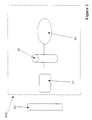
- Figure 1 shows a schematic depiction of apparatus 100 according to the present invention which comprises data capture means 20, data processing means 30 and indicator means 40.
- the data capture means 20 is in communication with the data processing means 30, which in turn is in communication with indicator means 40.
- the apparatus 100 is arranged so that the data capture means is, in use, located sufficiently close to the timber element 10 to be tested such that the magnitude of the test signal from the timber element is significantly larger than any background noise.
- the test procedure is initiated by striking the timber element 10 with a tool, preferably a hammer or similar, to produce an acoustic signal which is then captured by the data capture means 20.
- the acoustic signal is then fed to the data processing means, which transforms the acoustic signal from the time domain to the frequency domain and preferably processes further the frequency spectrum of the acoustic signal.
- the data processing means then extracts a component from the frequency spectrum, for example a frequency associated with a significant rate of change in the frequency spectrum or the frequency at which the frequency spectrum of the acoustic signal is substantially its maximum value, etc.
- the indicator means indicates to the user of the apparatus whether the pole is safe to climb or not, either by means of, for example, a visual display or by producing audible tones or a voiced output.
- the indicator means may alternatively give an indication of the level of decay which is judged to be present in the timber element, the user of the apparatus interpreting this indication when deciding whether to proceed with a particular course of action or not. Additionally, if the test result indicates that the timber element is structurally safe but close to the safety threshold, this information may be used to place the timber element in a programme of remedial work or replacement.
- the data capture means 20 comprises a microphone 21 and a DAT (Digital Audio Tape) recorder 22
- the data processing 30 means comprises a fast Fourier transform (FFT) analyser 31 and a personal computer 32.
- the indicator means 40 was provided by the monitor of the personal computer 41.
- the FFT analyser performed a fast Fourier transform in order to transform the acoustic response of the telegraph pole from the time domain to the frequency domain. The frequency spectrum was then smoothed to minimise the background noise and other random events.
- Reynolds, op cit discloses the acoustic characteristic of such a vibrating element (see Figure 3), which indicates that such vibrating elements act as a precise high-pass filter with a cut-off frequency dependent upon the natural frequency of the element.
- the natural frequency of a timber element can thus be found by determining the frequency at which the smoothed frequency spectrum has its maximum value, or by determining a frequency element that is characteristic of the frequency spectrum, i.e. by selecting a frequency element from either the rising edge before the spectrum maximum or the falling edge following the spectrum maximum. This natural frequency of the timber element, or a frequency characteristic of the frequency spectrum, can then be used to determine the state of the timber element.
- the microphone 21 was a 1 ⁇ 2" Falcon microphone and preamplifier type 2662
- the DAT recorder 22 was a TEAC RD-130TE 8 channel data recorder
- the FFT analyser 31 was a Ono Sokki CF210 FFT analyser.
- a personal computer processed the FFT data using Microsoft Excel.
- the microphone was positioned approximately 60cm above ground level at a distance of approximately 1 metre from the pole under test, the microphone being pointed at the pole. Some of the poles had no decay, others had some physical damage (i.e. from an impact) but no decay and a number had some level of decay, either interior decay, exterior decay or a combination of both interior and exterior decay.
- the data recorded by the data recorder was processed by the FFT analyser and the resulting acoustic spectrum was then smoothed, using Microsoft Excel, by averaging each data point in the spectrum with the two data points preceding it and the two data points following it.
- this smoothing of the acoustic spectra some of the spectra still contained a number of peaks at or near to the maximum point of the spectrum and some noise spikes were still present on the rising and falling edges, although in general the noise spikes were more prevalent on the falling edge.
- Figure 4 shows the smoothed frequency spectrum obtained from one of the tests, with the amplitude of the acoustic response (in arbitrary units) being plotted against the frequency of the acoustic response (in hertz).
- the spectrum has three main regions:
- background noise constitutes the spectrum for frequencies below approximately 200 Hz and above approximately 900 Hz.
- the rising edge region is approximately linear and is relatively free from spikes (which are due to background noise, interference, etc.).
- the peak region contains two peaks having a similar magnitude, but it is not entirely clear whether these peaks are a component of the acoustic response of the pole or are caused by background noise.
- the falling edge region contains a number of peaks, which are probably caused by background noise, whilst the spectrum is not particularly linear over the region (even when the peaks are discounted).
- an amplitude which is a fraction of the maximum amplitude of the frequency spectrum can be selected so that the frequency at which the spectrum first reaches that amplitude is within the rising edge region.
- the spectrum amplitude over the rising edge region varies from approximately 800 to 3400 units.
- the maximum amplitude of the spectrum (A 0 ) was 3980, giving a range for the fractional amplitude, within which the selected frequency component must be, of 0.20A 0 to 0.85A 0 (although, clearly, these values will depend upon the characteristics of the frequency spectrum under analysis).
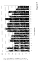
- Figure 5 shows the selected frequency components for the telegraph pole tests for a number of different tests (the frequency spectrum shown in Figure 4 is that which was generated in test 1 of Figure 5) with the selected frequency component being that at which the amplitude of the frequency spectrum first reached 50% of the maximum value.
- the results indicate that for poles with some decay the selected frequency component is less than approximately 275 Hz, whilst for those poles without any decay the selected frequency component is greater than approximately 275 Hz.
- the selected frequency component can be used as an indicator of whether the pole has any decay by comparison with a set of reference data.
- the selected frequency component can be compared with a single data point to give a safe/unsafe indication or with a larger data set to give an indication of the extent of the decay within the pole.
- This comparison with a set of reference data is only valid if the method used to select the frequency component when compiling the reference data is the same as, or sufficiently similar so as to obtain substantially the same results, as the method used to select the frequency component when testing timber elements for decay.
- the timber elements to be tested may be telegraph poles, as are used in telecommunications and utility networks, but the method, and the apparatus, of the present invention is equally suitable for use with structural timber elements, i.e. joists, beams, planking, etc. commonly found in buildings and other structures.
- structural timber elements i.e. joists, beams, planking, etc. commonly found in buildings and other structures.
- the timber element may be a tree or a branch of a tree.
- the test apparatus may take a number of forms.
- the data capture means may be any digital recording apparatus e.g. DAT (Digital Audio Tape), MiniDisc, DCC (Digital Compact Cassette), recordable CD (Compact Disc) or DVD (Digital Versatile Disc), hard disk, etc.
- analogue recording apparatus means may be used, with suitable digital to analogue conversion being used if the data processing is to be performed using digital data rather than analogue data, digital data processing normally being preferred due to its greater availability and flexibility.
- the entire apparatus may be implemented using a personal computer (PC) equipped with a microphone, the PC digitising and storing the test data and using appropriate software to process the data, extract the required frequency component and then indicating the test result using either the display or the computer's audio capabilities.
- Software suitable for carrying out the method of the present invention may be supplied on conventional computer media, e.g. floppy disk, CD-ROM, DVD, etc., or over a computer or communications network.
- the identification means of the apparatus may give a simple indication of the timber element's condition e.g. safe or unsafe, using a display panel or by emitting associated sounds.
- the apparatus may give an indication of the condition of the timber element by displaying, for example a rating of the condition of the element or placing the element in a category indicating the condition of the element. This information could then be interpreted by the apparatus user when determining whether the timber element is safe or not.
- the apparatus of the invention were to be used widely by the field staff who maintain a utility network then it would be preferred to minimise the size and cost of the apparatus and to ruggedise the apparatus so that it would be capable of being used in the range of temperatures, environments, etc. to which it would be exposed during such usage. It may be preferred to add some form of communications capability so that the apparatus could transfer data to or from a database holding information regarding pole identity and pole characteristics. Such data could be analysed to show trends in pole condition over time and could be used to initiate repair or replacement activities before a pole poses a safety hazard. It may be possible to integrate the functionality of the test apparatus with that of other equipment carried by field staff in order to reduce complexity.
- test method of the invention could, in principle, be carried out using a mobile phone to capture an acoustic signal when struck with a hammer or the like, the signal being carried over the mobile phone network to a central computer which stores the reference data and performs the comparison step.
- a mobile phone to capture an acoustic signal when struck with a hammer or the like
- the signal being carried over the mobile phone network to a central computer which stores the reference data and performs the comparison step.
- the acoustic properties of the mobile phone and the mobile phone network would need to be taken into account in defining the reference data and comparison process.
Landscapes
- Physics & Mathematics (AREA)
- Health & Medical Sciences (AREA)
- Life Sciences & Earth Sciences (AREA)
- Chemical & Material Sciences (AREA)
- Analytical Chemistry (AREA)
- Biochemistry (AREA)
- General Health & Medical Sciences (AREA)
- General Physics & Mathematics (AREA)
- Immunology (AREA)
- Pathology (AREA)
- Acoustics & Sound (AREA)
- Investigating Or Analyzing Materials By The Use Of Ultrasonic Waves (AREA)
Priority Applications (1)
| Application Number | Priority Date | Filing Date | Title |
|---|---|---|---|
| EP99305703A EP1070961A1 (de) | 1999-07-19 | 1999-07-19 | Testgerät |
Applications Claiming Priority (1)
| Application Number | Priority Date | Filing Date | Title |
|---|---|---|---|
| EP99305703A EP1070961A1 (de) | 1999-07-19 | 1999-07-19 | Testgerät |
Publications (1)
| Publication Number | Publication Date |
|---|---|
| EP1070961A1 true EP1070961A1 (de) | 2001-01-24 |
Family
ID=8241528
Family Applications (1)
| Application Number | Title | Priority Date | Filing Date |
|---|---|---|---|
| EP99305703A Withdrawn EP1070961A1 (de) | 1999-07-19 | 1999-07-19 | Testgerät |
Country Status (1)
| Country | Link |
|---|---|
| EP (1) | EP1070961A1 (de) |
Cited By (7)
| Publication number | Priority date | Publication date | Assignee | Title |
|---|---|---|---|---|
| EP1517141A1 (de) * | 2003-09-19 | 2005-03-23 | SAG Energieversorgungslösungen GmbH | Verfahren zur Überprüfung der Standsicherheit von teilweise in einen Untergrund eingelassenen Metallmasten |
| WO2010128056A1 (de) * | 2009-05-05 | 2010-11-11 | Meyer, Axel | Verfahren und vorrichtung zur prüfung der standsicherheit eines mastes |
| ITMI20091272A1 (it) * | 2009-07-17 | 2011-01-18 | Vodafone Omnitel Nv | Metodo e sistema per monitorare una struttura snella |
| JP6416355B1 (ja) * | 2017-10-03 | 2018-10-31 | 住友林業株式会社 | 固有振動数により丸太の含水率を測定する方法 |
| EP3415893A1 (de) * | 2017-06-16 | 2018-12-19 | Shimadzu Corporation | Auswertungsverfahren einer schlagprüfung und schlagprüfer |
| EP3415894A1 (de) * | 2017-06-16 | 2018-12-19 | Shimadzu Corporation | Auswertungsverfahren einer schlagprüfung und schlagprüfer |
| US11175263B2 (en) | 2020-02-24 | 2021-11-16 | King Fahd University Of Petroleum And Minerals | Apparatus and method for generating, measuring, and evaluating vibrational modes in cylindrical objects |
Citations (3)
| Publication number | Priority date | Publication date | Assignee | Title |
|---|---|---|---|---|
| US4399701A (en) * | 1980-06-03 | 1983-08-23 | Unisearch Limited | Method and means for detecting decay in wood |
| US5224381A (en) * | 1989-12-01 | 1993-07-06 | Sandes S.A. | Apparatus for automatically and non-destructively determining the class of standardized mechanical properties of a sample of hygroscopic material |
| US5621172A (en) * | 1995-04-03 | 1997-04-15 | State Of Oregon Acting By And Through The State Board Of Higher Education On Behalf Of Oregon State University | Method and apparatus for testing material strengths |
-
1999
- 1999-07-19 EP EP99305703A patent/EP1070961A1/de not_active Withdrawn
Patent Citations (3)
| Publication number | Priority date | Publication date | Assignee | Title |
|---|---|---|---|---|
| US4399701A (en) * | 1980-06-03 | 1983-08-23 | Unisearch Limited | Method and means for detecting decay in wood |
| US5224381A (en) * | 1989-12-01 | 1993-07-06 | Sandes S.A. | Apparatus for automatically and non-destructively determining the class of standardized mechanical properties of a sample of hygroscopic material |
| US5621172A (en) * | 1995-04-03 | 1997-04-15 | State Of Oregon Acting By And Through The State Board Of Higher Education On Behalf Of Oregon State University | Method and apparatus for testing material strengths |
Cited By (12)
| Publication number | Priority date | Publication date | Assignee | Title |
|---|---|---|---|---|
| EP1517141A1 (de) * | 2003-09-19 | 2005-03-23 | SAG Energieversorgungslösungen GmbH | Verfahren zur Überprüfung der Standsicherheit von teilweise in einen Untergrund eingelassenen Metallmasten |
| WO2010128056A1 (de) * | 2009-05-05 | 2010-11-11 | Meyer, Axel | Verfahren und vorrichtung zur prüfung der standsicherheit eines mastes |
| ITMI20091272A1 (it) * | 2009-07-17 | 2011-01-18 | Vodafone Omnitel Nv | Metodo e sistema per monitorare una struttura snella |
| WO2011007249A1 (en) * | 2009-07-17 | 2011-01-20 | Vodafone Group Plc | Method and system for monitoring a thin structure |
| EP3415893A1 (de) * | 2017-06-16 | 2018-12-19 | Shimadzu Corporation | Auswertungsverfahren einer schlagprüfung und schlagprüfer |
| EP3415894A1 (de) * | 2017-06-16 | 2018-12-19 | Shimadzu Corporation | Auswertungsverfahren einer schlagprüfung und schlagprüfer |
| CN109142101A (zh) * | 2017-06-16 | 2019-01-04 | 株式会社岛津制作所 | 冲击试验的评估方法及冲击试验机 |
| CN109142100A (zh) * | 2017-06-16 | 2019-01-04 | 株式会社岛津制作所 | 冲击试验的评估方法及冲击试验机 |
| JP2019002827A (ja) * | 2017-06-16 | 2019-01-10 | 株式会社島津製作所 | 衝撃試験の評価方法および衝撃試験機 |
| JP6416355B1 (ja) * | 2017-10-03 | 2018-10-31 | 住友林業株式会社 | 固有振動数により丸太の含水率を測定する方法 |
| JP2019066391A (ja) * | 2017-10-03 | 2019-04-25 | 住友林業株式会社 | 固有振動数により丸太の含水率を測定する方法 |
| US11175263B2 (en) | 2020-02-24 | 2021-11-16 | King Fahd University Of Petroleum And Minerals | Apparatus and method for generating, measuring, and evaluating vibrational modes in cylindrical objects |
Similar Documents
| Publication | Publication Date | Title |
|---|---|---|
| EP3270377B1 (de) | Beurteilung und anpassung einer audioinstallation | |
| US10446166B2 (en) | Assessment and adjustment of audio installation | |
| CA2137005C (en) | Method and apparatus for objective speech quality measurements of telecommunication equipment | |
| Steeneken et al. | Description of the RSG-10 noise database | |
| US5621854A (en) | Method and apparatus for objective speech quality measurements of telecommunication equipment | |
| CA2995530C (en) | Dynamic threshold methods, systems, computer readable media, and program code for filtering noise and restoring attenuated high-frequency components of acoustic signals | |
| US20050143997A1 (en) | Method and apparatus using spectral addition for speaker recognition | |
| US20150058002A1 (en) | Detecting Wind Noise In An Audio Signal | |
| CN108877814B (zh) | 窨井盖盗损检测方法、智能终端及计算机可读存储介质 | |
| EP1070961A1 (de) | Testgerät | |
| CN116564332A (zh) | 频响分析方法、装置、设备及存储介质 | |
| Barnwell III | Objective measures for speech quality testing | |
| CN109682463B (zh) | 变电站可听噪声测量方法 | |
| Song et al. | Annoyance measurement of singapore urban environmental noise | |
| Montano | Low frequency noise and infrasound: A new method to determine the specific sound from the total sound; a plausible statistical algorithm for use in Legal Noise Assessment | |
| Benson | A real-time blast noise detection and wind noise rejection system | |
| Gomery et al. | Fence vibrations [intruder detection] | |
| Yonemura et al. | Measurement of masked threshold of low-frequency tones in outdoor and indoor environmental background noise | |
| Prodeus et al. | Some Aspects of Speech Intelligibility Measuring Under Noise Dominance | |
| Yokoyama et al. | Perception of low-frequency components contained in general environmental noises including wind turbines | |
| de la Rosa et al. | Subterranean termite detection using the spectral kurtosis | |
| Rumsey | Forensic audio analysis | |
| Gomery et al. | Fence vibrations | |
| CN117219123A (zh) | 基于swm的回放攻击检测方法、装置、电子设备、存储介质 | |
| JPH02162495A (ja) | 雪崩検知装置 |
Legal Events
| Date | Code | Title | Description |
|---|---|---|---|
| PUAI | Public reference made under article 153(3) epc to a published international application that has entered the european phase |
Free format text: ORIGINAL CODE: 0009012 |
|
| AK | Designated contracting states |
Kind code of ref document: A1 Designated state(s): AT BE CH CY DE DK ES FI FR GB GR IE IT LI LU MC NL PT SE |
|
| AX | Request for extension of the european patent |
Free format text: AL;LT;LV;MK;RO;SI |
|
| STAA | Information on the status of an ep patent application or granted ep patent |
Free format text: STATUS: THE APPLICATION IS DEEMED TO BE WITHDRAWN |
|
| 18D | Application deemed to be withdrawn |
Effective date: 20001120 |