EP1070929B1 - Automotive air conditioning system evaporator - Google Patents
Automotive air conditioning system evaporator Download PDFInfo
- Publication number
- EP1070929B1 EP1070929B1 EP20000115565 EP00115565A EP1070929B1 EP 1070929 B1 EP1070929 B1 EP 1070929B1 EP 20000115565 EP20000115565 EP 20000115565 EP 00115565 A EP00115565 A EP 00115565A EP 1070929 B1 EP1070929 B1 EP 1070929B1
- Authority
- EP
- European Patent Office
- Prior art keywords
- collector
- evaporator
- compartments
- compartment
- pipes
- Prior art date
- Legal status (The legal status is an assumption and is not a legal conclusion. Google has not performed a legal analysis and makes no representation as to the accuracy of the status listed.)
- Expired - Lifetime
Links
Images


Classifications
-
- F—MECHANICAL ENGINEERING; LIGHTING; HEATING; WEAPONS; BLASTING
- F28—HEAT EXCHANGE IN GENERAL
- F28F—DETAILS OF HEAT-EXCHANGE AND HEAT-TRANSFER APPARATUS, OF GENERAL APPLICATION
- F28F1/00—Tubular elements; Assemblies of tubular elements
- F28F1/02—Tubular elements of cross-section which is non-circular
- F28F1/022—Tubular elements of cross-section which is non-circular with multiple channels
-
- F—MECHANICAL ENGINEERING; LIGHTING; HEATING; WEAPONS; BLASTING
- F28—HEAT EXCHANGE IN GENERAL
- F28D—HEAT-EXCHANGE APPARATUS, NOT PROVIDED FOR IN ANOTHER SUBCLASS, IN WHICH THE HEAT-EXCHANGE MEDIA DO NOT COME INTO DIRECT CONTACT
- F28D1/00—Heat-exchange apparatus having stationary conduit assemblies for one heat-exchange medium only, the media being in contact with different sides of the conduit wall, in which the other heat-exchange medium is a large body of fluid, e.g. domestic or motor car radiators
- F28D1/02—Heat-exchange apparatus having stationary conduit assemblies for one heat-exchange medium only, the media being in contact with different sides of the conduit wall, in which the other heat-exchange medium is a large body of fluid, e.g. domestic or motor car radiators with heat-exchange conduits immersed in the body of fluid
- F28D1/04—Heat-exchange apparatus having stationary conduit assemblies for one heat-exchange medium only, the media being in contact with different sides of the conduit wall, in which the other heat-exchange medium is a large body of fluid, e.g. domestic or motor car radiators with heat-exchange conduits immersed in the body of fluid with tubular conduits
- F28D1/053—Heat-exchange apparatus having stationary conduit assemblies for one heat-exchange medium only, the media being in contact with different sides of the conduit wall, in which the other heat-exchange medium is a large body of fluid, e.g. domestic or motor car radiators with heat-exchange conduits immersed in the body of fluid with tubular conduits the conduits being straight
- F28D1/0535—Heat-exchange apparatus having stationary conduit assemblies for one heat-exchange medium only, the media being in contact with different sides of the conduit wall, in which the other heat-exchange medium is a large body of fluid, e.g. domestic or motor car radiators with heat-exchange conduits immersed in the body of fluid with tubular conduits the conduits being straight the conduits having a non-circular cross-section
- F28D1/05366—Assemblies of conduits connected to common headers, e.g. core type radiators
- F28D1/05391—Assemblies of conduits connected to common headers, e.g. core type radiators with multiple rows of conduits or with multi-channel conduits combined with a particular flow pattern, e.g. multi-row multi-stage radiators
-
- F—MECHANICAL ENGINEERING; LIGHTING; HEATING; WEAPONS; BLASTING
- F28—HEAT EXCHANGE IN GENERAL
- F28F—DETAILS OF HEAT-EXCHANGE AND HEAT-TRANSFER APPARATUS, OF GENERAL APPLICATION
- F28F9/00—Casings; Header boxes; Auxiliary supports for elements; Auxiliary members within casings
- F28F9/02—Header boxes; End plates
- F28F9/0202—Header boxes having their inner space divided by partitions
- F28F9/0204—Header boxes having their inner space divided by partitions for elongated header box, e.g. with transversal and longitudinal partitions
- F28F9/0214—Header boxes having their inner space divided by partitions for elongated header box, e.g. with transversal and longitudinal partitions having only longitudinal partitions
-
- F—MECHANICAL ENGINEERING; LIGHTING; HEATING; WEAPONS; BLASTING
- F28—HEAT EXCHANGE IN GENERAL
- F28F—DETAILS OF HEAT-EXCHANGE AND HEAT-TRANSFER APPARATUS, OF GENERAL APPLICATION
- F28F9/00—Casings; Header boxes; Auxiliary supports for elements; Auxiliary members within casings
- F28F9/26—Arrangements for connecting different sections of heat-exchange elements, e.g. of radiators
- F28F9/262—Arrangements for connecting different sections of heat-exchange elements, e.g. of radiators for radiators
-
- F—MECHANICAL ENGINEERING; LIGHTING; HEATING; WEAPONS; BLASTING
- F28—HEAT EXCHANGE IN GENERAL
- F28D—HEAT-EXCHANGE APPARATUS, NOT PROVIDED FOR IN ANOTHER SUBCLASS, IN WHICH THE HEAT-EXCHANGE MEDIA DO NOT COME INTO DIRECT CONTACT
- F28D21/00—Heat-exchange apparatus not covered by any of the groups F28D1/00 - F28D20/00
- F28D2021/0019—Other heat exchangers for particular applications; Heat exchange systems not otherwise provided for
- F28D2021/008—Other heat exchangers for particular applications; Heat exchange systems not otherwise provided for for vehicles
- F28D2021/0085—Evaporators
-
- F—MECHANICAL ENGINEERING; LIGHTING; HEATING; WEAPONS; BLASTING
- F28—HEAT EXCHANGE IN GENERAL
- F28F—DETAILS OF HEAT-EXCHANGE AND HEAT-TRANSFER APPARATUS, OF GENERAL APPLICATION
- F28F2225/00—Reinforcing means
- F28F2225/08—Reinforcing means for header boxes
Definitions
- the invention concerns an automotive air conditioning system evaporator.
- An automotive air conditioning system heat exchanger having a longitudinally-extending collector, defining a first and a second compartment, each having a coolant inlet or respectively a coolant outlet, the collector defining plural slots each extending into both said compartments, plural pipes extending from the slots to a flow-return device, is known from US-A-5 174 373 , being suitable for a condenser.
- evaporators which structure includes a plurality of identical rows of flattened tubes. Each of the rows is slightly spaced from adjacent other ones of the rows.
- upper and lower manifold comprise a plurality of elongated headers tubes.
- the flattened tubes are in fluid communication with the interior of the upper and lower header tubes thus establish fluid communication between the two headers.
- Those evaporator structures are not optimized from the point of view of installation volumes.
- duplex heat exchangers where two rows of flat pipe arrays are arranged one behind the other with clearance to allow air circulation, connected with the internal heat exchange fluid via circular pipe shaped collectors, in which the collectors for these conventional duplex heat exchangers have a circular interior cross-section free from transverse subdivisions.
- both rows of the flat pipe array can be interconnected with one another in various ways by means of connection leads. This is also taken into account in the event of use as an evaporator.
- both flat pipe arrays arranged behind one another in the surrounding air, are fed by different internal heat exchange fluids, e.g. on one hand by means of the cooling water in an engine cooling system and, on the other, by means of the forced air or engine oil acting as the coolant in an automotive air conditioning system.
- the collectors are not sub-divided transversely into two successive compartments, isolated from each other by means of a longitudinal divider.
- One embodiment of the invention provides an automotive air conditioning system evaporator with only a single row of pipes, hence a simplex evaporator which, with both manufacturing depth for the pipes in the circulating air and coolant operating pressure pre-determined, has the lowest possible dimensions from the point of view of installation volumes and wall thicknesses and, with this, also uses the minimum amount of material. Moreover, for optimisation, particular attention is to be paid to the fact that, in this type of evaporator, the interior of the collector is divided transversely into two different compartments.
- coolant inflow and return flow to both compartments are arranged to take place concurrently whereas, in the case where there is an uneven number of flows, inflow and return flow to the same compartment can be provided, however, in association with different interior areas which, in the same compartment, are separated from each other by means of at least one transverse partition.
- Duplex heat exchangers suffice to begin with for the requirement of the above problem definition, especially in the context of optimising the manufacturing volumes, even if both flat pipe arrays have fins passing through them (e.g. Figs. 16 and 17 of EP 0 414 433 A2 ).
- an automotive air conditioning system evaporator according to claim 1.
- each of the two collector compartments is rounded for stability under pressure and in the ideal case is, in addition, circular in cross-section.
- Its operation, according to the invention also becomes correspondingly obvious, if a collector's total circular cross-section as specified in US patent 5 174 373 is compared with a collector's individual circular cross-sections according to the invention, given the two prerequisites that both circular cross-sections of both compartments are identical and shall be measured on the same manufactured depth of the flat pipes. It then follows that, in the invention, an individual compartment's circular cross-section is about half the diameter of the circular cross-section of the complete collector as specified in US Patent 5 174 373 .
- the lowering in the circular cross-section diameter corresponds with a factor of two, as well as perhaps to lowering the wall thickness required to about half its value. In this way, savings in material requirements and costs are already achieved. Moreover, a considerable saving in the building-in height, which in any event is barely adequate behind the dashboard inside the vehicle, results.
- coolants such as the widely employed R 134a coolant are still used for automotive air conditioning system evaporators, whose operating pressure is in the region of 10 to 30 bar.
- natural coolants such as e.g. CO2
- CO2 which are used in evaporators at operating pressures from 40 to 80 bar.
- An integral construction with a first circular pipe and a second circular pipe for the construction of a collector for a duplex heat exchanger is known from DE-G 91 11 412.8 U1 , in particular Fig. 4 with its description.
- the longitudinal divider between both circular cross-section compartments is already manufactured from the start as an integral component. This concept can also be transferred to the simplex evaporator as specified the invention.
- the invention is an alternative design providing an integral component with a longitudinal slot, into which a separate component is inserted on the outside to form a longitudinal divider between both compartments.
- This separate component which of course engages in a transverse slot, permits both compartments to be tightly sealed against the front face of the inserted flat pipe in a particularly advantageous way at any given time and is otherwise common with both compartments in Fig. 4 of DE-G 91 11 412.8 U1 .
- the longitudinal divider inserted as a separate component is perhaps formed from sheet metal pre-coated with solder, it is possible to use the solder oven to solder this sheet with ease to the front face of the flat pipe in the event of hard soldering an aluminium or aluminium alloy construction.
- insert slots matched to the profile of the flat pipes in the context of the maximum permissible tolerances, are manufactured as a separate capping component, to which matching can be achieved in a much easier way than to an incorporated collector or even only to an incorporated component wall.
- a capping component can be formed from sheet metal in a way which is much simpler and then bent appropriately. If this sheet is then also coated with solder, a solder carrier to solder the flat pipes with the collector is obtained at the same time.
- a typical capping component, formed from sheet metal can also be manufactured without difficulty with collars extending the insert slots to the interior and/or the exterior and allowing solder to form a surface bond between the inner surface of the collars and the external surfaces of the flat pipes.
- transverse slots it is possible to manage the manufacture of the transverse slots in the collector itself with a lower demand for accuracy without detriment to the end result. For example, it is possible to cut in the transverse slots with a simple milling cutter following extrusion or a similar integral manufacturing process.
- compartments in the flat pipe served by the internal heat exchange fluid shall be, as far as possible, able to use even the wall thickness region of the longitudinal divider, in a different way to US Patent 5 174 373 .
- Another solution is proposed concerning the wall thickness area of this longitudinal divider, as well as a solution regarding an extension of the transverse slot into the thickness of the actual collector wall.
- transverse slot regions which are still opposite the actual collector wall area and/or the longitudinal divider on the front face of each flat pipe, internal recessing of the transverse slot is effected, such that uninterrupted communication between the relevant compartment in the collector and the critical flat pipe compartments mentioned can be achieved at that point.
- Precise matching to the flat pipes is also invariably achieved by means of the capping component with its machined insert slots. It has been shown that the extremely narrow transverse slot dimensions in the collector cover, in association with the installed capping component and the inserted flat pipes, do not adversely affect collector wall thickness dimensioning requirements, as any material weakness in the collector wall is again compensated by addition of the inserted parts and the solder used.
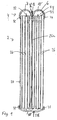
- Fig. 1 shows the basic construction of a dual flow automotive air conditioning system evaporator 2 as specified in the invention. It is preferable to produce the complete evaporator (or parts thereof) using aluminium or aluminium alloy such as e.g. AlMn1 and hard soldered components, for example by means of hard solder in its AlSi7-12 form.
- aluminium or aluminium alloy such as e.g. AlMn1
- hard soldered components for example by means of hard solder in its AlSi7-12 form.
- Evaporator 2 has a flat pipe array 20, interconnected by means of zigzag fins 21 ( Fig. 4 ) for heat transfer purposes.
- each flat pipe 20 on the outside of the array is fitted with a zigzag fin, which can be followed externally by a metal finishing sheet (not illustrated), which can form part of a framework for the array. It is preferable to effect the heat transfer connection at the same time by hard soldering the zigzag fins 21 to the flat pipes 20 and, if necessary, to each metal finishing sheet.
- the flat pipes 20 are set in the array substantially at equal intervals and, when installed in the automotive air conditioning system, mainly arranged vertically in the diagram layer portrayed in Fig. 1 .
- the surrounding air is circulated mainly as an external heat exchange medium in the horizontal plane as shown in the diagram layer in Fig. 1 as specified by the double line arrows in Fig. 5 and Fig. 5a .
- the coolant acting as the internal heat exchange medium is fed as a dual flow through each individual flat pipe 20, in which the arrows depicted in Fig. 1 indicate the two flows 22 and 24, namely Flow 22 on the inflow side with the downward pointing arrow in Fig. 1 and Flow 24 on the outflow side with the upward pointing arrow in Fig. 1 .
- a plurality or multiplicity of channels 26 is formed over the full cross-section length of each individual flat pipe 20 over which the two flows are divided, e.g. at any given time, an identical number of channels 26 is assigned to each flow 22 or 24.
- the same ends 23 of the flat pipes 20 communicate with the interior of a collector 4, which is extended outwards at an angle of 90 DEG to the flat pipes 20 (compare Figs. 4 to 5a ); in its transverse direction (diagram layer in Figs. 1 to 3a ), the collector 4 is divided into two compartments 8 and 10, which are completely, or at least to a considerable degree, separated from each other by means of an intermediate partition 12.
- the collector cover 6 forms a pipe base or contributes to its formation.
- the collector cover 6 is divided over its length, in the dimension in which the flat pipe array 20 is divided, mainly at equally spaced intervals, by transverse slots 18 which are common to both compartments 8 and 10, into which each flat pipe 20 in the flat pipe array 20 engages its same nominated end 23 for the purpose of sealing it.
- This end 23 of the flat pipe 20 is therefore, just as with transverse slot 18, common to both compartments 8 and 10.
- the front faces of the ends 23 of the flat pipes 20 are at the same time aligned over the length of both the individual flat pipe 20 and the collector 4.
- a return flow device 28 which switches the first flow 22 to the second flow 24 in each individual flat pipe 20.
- a return flow device 28 There are numerous design options for such a return flow device 28. Without any limitation as to generality, this is shaped in Fig. 1 as bowl 30 which, with its sidewall 31, is crimped as specified in Fig. 1 , holding fast the exterior of each flat tube 2.
- each flat pipe 20 can be associated with an individual bowl 30. It is also possible to interconnect such bowls or build up the appropriate bowl shaped return flow structure into a single integral component. Essentially, its function is the return of the two flows 22 and 24 in each flat tube 20.
- evaporator 2 the coolant used as the internal heat exchange fluid is fed as an opposing cross-flow with respect to the direction of flow of the surrounding air.
- Figs. 5 and 5a the direction of flow of the coolant is illustrated with the horizontally aligned double walled arrows.
- the collector 4 coolant inlet 14 and the collector 4 coolant outlet 16 are formed at any given time on a front facing sealing wall 15 or 17 of the collector 4, e.g. as illustrated, as an external connection nipple on a disc shaped sealing wall 15 or 17, which is enclosed securely in the collector cover 6.
- inlet 14 and outlet 16 are associated at the same time with the same sealing wall 15 whereas, in the design form specified in Fig. 5a , inlet 14 is associated with a sealing wall 15 and outlet 16 is associated with another sealing wall 17.
- inlet 14 leads into compartment 10, facing away from the direction of flow of the coolant and outlet 16 issues from compartment 8, facing towards the circulating surrounding air.
- both compartments 8 and 10 at any given time are divided into two sub-compartments 50 and 52 or 54 and 56 by means of a transverse partition 9 in which, in the case of Fig. 5 , inlet 14 is extended through transverse partition 9 into compartment 10 via an intermediate pipe connection 13.
- Fig. 1 The basic principle of using the coolant to produce the flow through evaporator 2 is depicted in Fig. 1 .
- the coolant which has entered compartment 8, as specified in the design depicted in Fig. 1 is routed to the appropriate flat pipe 20 along the first flow 22 by means of the first halves of the channels 26, then switched to the return flow device 28 and routed in the opposite direction back to compartment 6 through the second halves of the channels 26. If this direction of flow is provided over the entire length of the evaporator, Fig. 1 with an opposing cross-flow taken as a basis is to be a pre-requisite for flow of the surrounding air on the right hand side in the diagram layer. In preferred development, however, it can even be provided by means of a type of flow as specified in Figs. 5 and 5a by way of example
- the coolant entering through inlet 14 runs first into sub-compartment 52 of compartment 10, then through the associated flat pipes 20 into sub-compartment 56 of compartment 8, from this through the associated flat pipes 20 into sub-compartment 50, again in compartment 10, and, finally, once more via the associated flat pipes 20 through sub-compartment 54 yet again from compartment 8 to outlet 16.
- the full collector 4 length is used, although inlet 14 and outlet 16 are placed on the same front face of collector 4.
- a corresponding progressive flow is effected along collector 4 from inlet 14 to outlet 16; first from inlet 14 into suh-compartment 50, from this via the associated or common flat pipes 20 into sub-compartment 54. From here, via the associated or common flat pipes 20 into sub-compartment 52 and finally from here via the associated or common flat pipes 20 into sub-compartment 56, which is connected to outlet 16.
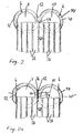
- each collector 4 is common to all evaporator 2 design forms: in developing the conventional design, namely for the collector cover 6 to be formed as a rounded shape for stability under pressure, this concept is applied to both walls 32 and 34 of the first compartment 8 as well as the second compartment 10 of the collector cover. Correspondingly, both walls 32 and 34 are each rounded for stability under pressure, or respectively even rounded to a circular shape in the design examples.
- Figure 2 also shows the purest form of one limiting case, in which both walls 32 and 34 are formed as a single integral component 44, which, moreover, even incorporates the intermediate partition 12 between both compartments 8 and 10.
- the intermediate partition 12 narrows, in addition tapering in the direction of the adjacent ends 23 of the flat pipes 20.
- the top of this narrow taper can, in addition, depending on the requirement, be formed as a wedge shape running towards a tip or be more or less flattened after the style of the narrow face on a flat crosspiece.
- Figure 2a also shows the other limiting case, where both walls 32 and 34 are respectively formed as a single integral component, in which both components, i.e. walls 32 and 34, are linked by a further component inset separately as longitudinal divider 36, in this case in the form of a flat material crosspiece 36, which for its part forms the intermediate partition 12 between compartments 8 and 10.
- both components i.e. walls 32 and 34
- longitudinal divider 36 in this case in the form of a flat material crosspiece 36, which for its part forms the intermediate partition 12 between compartments 8 and 10.
- the exterior profile of both walls 32 and 34 can remain completely rounded - in which case extreme deviations from the circular shape are possible - both flat sides of the further component are present in case 2a, hence, preferably opposite the flat material crosspiece 36, the flange type flattened sections 40 of a plinth shaped exterior attachment 36 set in the installation between both walls 32 and 34.
- the flange type flattened sections 40 of a plinth shaped exterior attachment 36 set in the installation between both walls 32 and 34.
- These additional flattened sections 40 are depicted in Fig. 2a to illustrate the alternative without fitting a plinth shaped attachment.
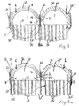
- Figs. 3 and 3a show a favoured mix between the two limiting cases cited. From the limiting case in Fig. 2 , it is assumed in addition that both walls 32 and 34 are formed from a single integral component 44.
- this further component 36 is enclosed securely, i.e. in general hard soldered, on the outside, in a longitudinal slot 46 between both rounding bends of the first and second walls 32 and 34, to the side of collector 4 facing away from the array of flat pipes 20
- the first alternative is illustrated in the design forms in Figs. 1 and 3 using a longitudinal divider 36 inserted as a separate component, but could also be correspondingly embodied with the intermediate partition 12 incorporated in the integral component 44 as specified in Fig. 2 , particularly in the configuration tapering to a tip.
- the intermediate partition 12 engages as if it were a flow in a channel 26a which is not used and is, in addition, anchored securely between its two channel walls.
- this channel 26a used appropriately only to divide the flow, has a narrower channel width than the remaining channels 26 of each flat pipe 20 unless this is essential. However, as a result of this narrower dimensioning the manufacturing depth of evaporator 2 is kept proportionately small.
- a minimum manufacturing depth is obtained by following the alternative as specified in Figs 2, 2a and 3a .
- the intermediate partition 12 which can be formed with an integral component 44 as specified in Fig. 2 or shaped as a separate component as specified in Figs. 2a and 3a , works in concert with the outside edge 58 of a completely standard intermediate partition 60 between channels 26 of each flat pipe 20 acting in a flow-like manner. In this way, the separation is achieved in a flow-like manner with no additional manufacturing depth being required.
- Figs. 3, 3a and 4 show the following:
- the first and second walls 32 and 34 of the collector cover 6 are formed as the integral component 44, which, in the form depicted, can be manufactured as an impact extruded component.
- the collector cover 6 is provided in its centre with the longitudinal slot 46, into which the longitudinal divider 36 can be pushed from the outside.
- the longitudinal divider 36 is provided with a coating of solder for soldering to the front face 62 of the flat pipes 20 and sealing of the longitudinal slot 46, protruding externally from the collector cover 6 to ensure adequate solder provision.
- a capping component 64 is attached externally to the collector cover 6 in the area of the transverse slots 18.
- This capping component 64 is first placed on the collector cover 6 with as few solder slots as possible.
- existing collars from housing slots 72 in the capping component 64 for each flat pipe 20, showing internally, are pressed into the transverse slot 46 of the collector 4 if necessary.
- the soldering of the capping component 64 is effected, together with further soldered connections, in a continuous process oven using the so-called "One-Shot" method.
- AlSi 7-12 a non-corrosive fluoridic flowing material, is used as the hard solder for choice. Hard soldering is effected at a temperature of 600-610 DEG C.
- the former is first pressed into a device in the collector cover 6 and then, by folding both longitudinal edges 68 over a securing ridge 70 on the collector cover 6, is fastened to this.
- a direct housing slot 72 is formed in the capping component 64, together with the collar 66, into which the end 23 of the flat pipe 20 is inserted.
- Collar 66 is matched both to the dimensions of the flat pipe 20 and to the external profile of collector 4. In this way, gas-tight soldering of the capping component 64 with the collector cover 6 is achieved on the one hand and, on the other, the collar 66 of the capping component 64 is also connected with the ends of the flat pipes 20 in a gas-tight fashion.
- the pipe division i.e. the spacings along the collector cover 6 of the flat pipes 20, is normally 6-15 mm
- the transverse slots 18 in the collector cover 6 must only be put in during the abovementioned cycle; in this way, the pressure sealing of the collector cover 6 is only slightly disturbed when the transverse slots 18 are milled.
- the transverse slot 18 in the collector cover 6 is recessed opposite the front face of the flat pipe 20. Guaranteed sealing between the first and second compartments 8 or 10 of the collector cover 6 is achieved by means of a longitudinal divider 36, the thickness of which does not depend on the internal overpressure in the collector cover 6, but merely on the difference in pressure between the first and second compartments 8 or 10, or is to be dimensioned, as the need arises, from the point of view of its technical production.
- the thickness of the first or second wall 32 or 34 for any given instance must be 2.5 mm, whereas the solder coated longitudinal divider 36 can be manufactured with a thickness of less than 0.2 mm. To achieve problem free mounting and provide sufficient solder as well as being capable of meeting tolerances, however, it should have a wall thickness of about 1 - 1.5 mm.
- the longitudinal divider 36 is pressed into a channel 26a in the flat pipe 20, which is not used for continuous flow, for the purpose of sealing against the front face 62 of the flat pipe 20.
- the longitudinal divider 36 provides a seal directly against an intermediate partition 60 between the adjacent channels 26 which provides a longitudinal path in the flat pipe 20, so as to avoid blocking the channels 26 completely.
- the transverse slot 18 in the collector cover 6 is recessed opposite the front face 62 of the flat pipe 20 by the distance 74, so that, at this point, both external channels 26b of the flat pipe 20 are not also closed off by the collector cover 6, but linked to provide flow between the first or second compartment 8 or 10.
- the capping cover 64 is continuously soldered to the long side of the transverse slot 18 as specified in Fig. 3 by means of the internally mounted collar 66, in the case of Fig.
- the capping component 64 must withstand the full evaporator 2 operating pressure on both front faces of the transverse slot 18. Because of transverse slot 18's small width, (2x the thickness of the capping component 64 plus the flat pipe thickness) of only 3 - 4 mm, however, the thickness of the capping component 64 amounts to 1 - 1.5 mm.
- the tasks and functions for the collector cover 6 are split up as follows, as specified in Figs 3 to 4 :
- the extruded or seamlessly drawn collector cover 6 provides a framework which copes with operating pressures and provides the pressure strengths required. As a result of the production process and its shape, it can already produce the pressure strength safety required, without being further affected by the Nocolok soldering process and variations in the evaporator production process.
- the capping component 64 provides the soldering material required. Furthermore, in the capping component 64, the minimum tolerances in the housing slots 72 of less than 0.2 mm required for soldering, as with the transverse slots 18 in the collector cover 6, can be produced more cost effectively by pressing, stamping and rolling.
Description
- The invention concerns an automotive air conditioning system evaporator.
- An automotive air conditioning system heat exchanger having a longitudinally-extending collector, defining a first and a second compartment, each having a coolant inlet or respectively a coolant outlet, the collector defining plural slots each extending into both said compartments, plural pipes extending from the slots to a flow-return device, is known from
US-A-5 174 373 , being suitable for a condenser. - The pipes in the external heat exchange medium, generally the air surrounding the vehicle, are arranged in series in conventional heat exchangers, in the same way as the evaporator in the invention. Bearing in mind the savings in material and space requirements which are achievable in this way, there have already been attempts to optimise for internal pressure by making the exterior profile of the collector a circular shape. There is, however, no optimising for internal pressure in both semi-circular compartments extending the length of the collector and complementing one another transversely.
- On one hand, there are evaporators which structure includes a plurality of identical rows of flattened tubes. Each of the rows is slightly spaced from adjacent other ones of the rows. In the evaporator cited in
EP 0 325 844 A1 , upper and lower manifold comprise a plurality of elongated headers tubes. The flattened tubes are in fluid communication with the interior of the upper and lower header tubes thus establish fluid communication between the two headers. Those evaporator structures are not optimized from the point of view of installation volumes. - On the other hand, there are conventional duplex heat exchangers where two rows of flat pipe arrays are arranged one behind the other with clearance to allow air circulation, connected with the internal heat exchange fluid via circular pipe shaped collectors, in which the collectors for these conventional duplex heat exchangers have a circular interior cross-section free from transverse subdivisions. In the duplex heat exchanger cited in
EP 0 414 433 A2 , both rows of the flat pipe array can be interconnected with one another in various ways by means of connection leads. This is also taken into account in the event of use as an evaporator. In the case of another conventional duplex heat exchanger, as specified inDE-G 91 11 412.8 U1 , both flat pipe arrays, arranged behind one another in the surrounding air, are fed by different internal heat exchange fluids, e.g. on one hand by means of the cooling water in an engine cooling system and, on the other, by means of the forced air or engine oil acting as the coolant in an automotive air conditioning system. Even in these conventional duplex heat exchangers, in which use as an evaporator is not taken into account, the collectors are not sub-divided transversely into two successive compartments, isolated from each other by means of a longitudinal divider. - One embodiment of the invention provides an automotive air conditioning system evaporator with only a single row of pipes, hence a simplex evaporator which, with both manufacturing depth for the pipes in the circulating air and coolant operating pressure pre-determined, has the lowest possible dimensions from the point of view of installation volumes and wall thicknesses and, with this, also uses the minimum amount of material. Moreover, for optimisation, particular attention is to be paid to the fact that, in this type of evaporator, the interior of the collector is divided transversely into two different compartments. In the case where there is an even number of flows in the evaporator (of at least dual flow capacity), coolant inflow and return flow to both compartments are arranged to take place concurrently whereas, in the case where there is an uneven number of flows, inflow and return flow to the same compartment can be provided, however, in association with different interior areas which, in the same compartment, are separated from each other by means of at least one transverse partition.
- Duplex heat exchangers suffice to begin with for the requirement of the above problem definition, especially in the context of optimising the manufacturing volumes, even if both flat pipe arrays have fins passing through them (e.g. Figs. 16 and 17 of
EP 0 414 433 A2 ). - According to the invention, there is provided an automotive air conditioning system evaporator according to claim 1.
- Thus with an evaporator constructed in a simplex arrangement of its flat pipe array, each of the two collector compartments is rounded for stability under pressure and in the ideal case is, in addition, circular in cross-section. Its operation, according to the invention, also becomes correspondingly obvious, if a collector's total circular cross-section as specified in
US patent 5 174 373 is compared with a collector's individual circular cross-sections according to the invention, given the two prerequisites that both circular cross-sections of both compartments are identical and shall be measured on the same manufactured depth of the flat pipes. It then follows that, in the invention, an individual compartment's circular cross-section is about half the diameter of the circular cross-section of the complete collector as specified inUS Patent 5 174 373 . For the identical internal pressure, the lowering in the circular cross-section diameter corresponds with a factor of two, as well as perhaps to lowering the wall thickness required to about half its value. In this way, savings in material requirements and costs are already achieved. Moreover, a considerable saving in the building-in height, which in any event is barely adequate behind the dashboard inside the vehicle, results. - Currently, coolants such as the widely employed R 134a coolant are still used for automotive air conditioning system evaporators, whose operating pressure is in the region of 10 to 30 bar. There are considerations, on environmental protection grounds, for employing natural coolants such as e.g. CO2, which are used in evaporators at operating pressures from 40 to 80 bar. It has been shown that the evaporator as specified in the invention is equally well suited to operation with CO2 as the coolant, as the saving in wall thickness becomes particularly and reassuringly apparent. It is even possible as of now to install the evaporator as specified in the invention using conventional coolants, without considerable cost increases or any kind of rework being required for later conversion to CO2 operation.
- An integral construction for the first wall, the second wall and/or an integral union of both walls and naturally favoured as an impact extruded, diecast or warm extruded part, is preferred on manufacturing and strength grounds. An integral construction with a first circular pipe and a second circular pipe for the construction of a collector for a duplex heat exchanger is known from
DE-G 91 11 412.8 U1 , in particularFig. 4 with its description. In this conventional integral construction, the longitudinal divider between both circular cross-section compartments is already manufactured from the start as an integral component. This concept can also be transferred to the simplex evaporator as specified the invention. The invention is an alternative design providing an integral component with a longitudinal slot, into which a separate component is inserted on the outside to form a longitudinal divider between both compartments. The use of this separate component, which of course engages in a transverse slot, permits both compartments to be tightly sealed against the front face of the inserted flat pipe in a particularly advantageous way at any given time and is otherwise common with both compartments inFig. 4 ofDE-G 91 11 412.8 U1 .If, in addition, the longitudinal divider inserted as a separate component is perhaps formed from sheet metal pre-coated with solder, it is possible to use the solder oven to solder this sheet with ease to the front face of the flat pipe in the event of hard soldering an aluminium or aluminium alloy construction. - For precision manufacture of the transverse slots to match the external profile of the flat pipes in the context of the permissible tolerances, it is possible to solder the flat pipes directly into the transverse slots of the relevant component. However, this requires an additional application of solder, perhaps by plasma spraying, as provided in the case of
DE-G 91 11 412.8 U1 (Fig.4 , Reference marking 75). - An alternative design form is preferred in which insert slots, matched to the profile of the flat pipes in the context of the maximum permissible tolerances, are manufactured as a separate capping component, to which matching can be achieved in a much easier way than to an incorporated collector or even only to an incorporated component wall. Such a capping component can be formed from sheet metal in a way which is much simpler and then bent appropriately. If this sheet is then also coated with solder, a solder carrier to solder the flat pipes with the collector is obtained at the same time. A typical capping component, formed from sheet metal, can also be manufactured without difficulty with collars extending the insert slots to the interior and/or the exterior and allowing solder to form a surface bond between the inner surface of the collars and the external surfaces of the flat pipes. Moreover, it is possible to manage the manufacture of the transverse slots in the collector itself with a lower demand for accuracy without detriment to the end result. For example, it is possible to cut in the transverse slots with a simple milling cutter following extrusion or a similar integral manufacturing process.
- In the simplex heat exchanger in
US patent 5 174 373 , from which the invention originates, just as in the duplex heat exchanger inEP 0 414 433 A2 as well as inDE-G 91 11 412.8 U1 , the dimensions of the transverse slot in the collector at any given time extended only partially over the internal diameter of the circular pipe cross-section. In the context of the problem defined by the invention, it attempts instead not only the entire draining of this inner pipe cross-section, but furthermore to extend the transverse slot length at any given time and, with this, the length of the applicable flat pipe in the direction of flow of the surrounding air providing the external heat exchange fluid in the vehicle. At the same time, moreover, compartments in the flat pipe served by the internal heat exchange fluid shall be, as far as possible, able to use even the wall thickness region of the longitudinal divider, in a different way toUS Patent 5 174 373 . Another solution is proposed concerning the wall thickness area of this longitudinal divider, as well as a solution regarding an extension of the transverse slot into the thickness of the actual collector wall. By using a milling cutter, a simpler method for manufacturing the transverse slot, it is possible to take into account both the previous requirements in a particularly simple way. In addition, it is important that, in the transverse slot regions, which are still opposite the actual collector wall area and/or the longitudinal divider on the front face of each flat pipe, internal recessing of the transverse slot is effected, such that uninterrupted communication between the relevant compartment in the collector and the critical flat pipe compartments mentioned can be achieved at that point. Precise matching to the flat pipes is also invariably achieved by means of the capping component with its machined insert slots. It has been shown that the extremely narrow transverse slot dimensions in the collector cover, in association with the installed capping component and the inserted flat pipes, do not adversely affect collector wall thickness dimensioning requirements, as any material weakness in the collector wall is again compensated by addition of the inserted parts and the solder used. - Finally, conventional circuits can also be provided in the evaporator as specified in the invention, in which, in particular, both compartments can be divided into sub-compartments along the collector.
- Embodiments of the invention will now be described by way of example only, with reference to the accompanying drawings, in which:
-
Fig. 1 - shows a cross-section through an evaporator as specified in the invention; -
Figs. 2, 2a ,3 and 3a show scaled-up partial collector area cross-sections through various variants of an evaporator as specified in the invention, in whichFig. 3 develops the actual design form shown inFig. 1 ; -
Fig 2 ,3 and 3a are eat part of the invention. -
Fig. 4 shows a partial longitudinal section through a variant of the collector as specified inFigs. 2 and3 as well as -
Figs 5 and 5a each show a longitudinal section through the collector of an evaporator as specified in the invention, viewed along the flat pipes, and naturally as two variants, namely triple flow (Fig. 5 ) and quadruple flow (Fig. 5a ) circuit configurations. - In the various figures, like reference numerals refer to like parts.
-
Fig. 1 shows the basic construction of a dual flow automotive air conditioning system evaporator 2 as specified in the invention. It is preferable to produce the complete evaporator (or parts thereof) using aluminium or aluminium alloy such as e.g. AlMn1 and hard soldered components, for example by means of hard solder in its AlSi7-12 form. - Evaporator 2 has a
flat pipe array 20, interconnected by means of zigzag fins 21 (Fig. 4 ) for heat transfer purposes. In general, eachflat pipe 20 on the outside of the array is fitted with a zigzag fin, which can be followed externally by a metal finishing sheet (not illustrated), which can form part of a framework for the array. It is preferable to effect the heat transfer connection at the same time by hard soldering thezigzag fins 21 to theflat pipes 20 and, if necessary, to each metal finishing sheet. Theflat pipes 20 are set in the array substantially at equal intervals and, when installed in the automotive air conditioning system, mainly arranged vertically in the diagram layer portrayed inFig. 1 . In addition, the surrounding air is circulated mainly as an external heat exchange medium in the horizontal plane as shown in the diagram layer inFig. 1 as specified by the double line arrows inFig. 5 and Fig. 5a . The coolant acting as the internal heat exchange medium is fed as a dual flow through each individualflat pipe 20, in which the arrows depicted inFig. 1 indicate the twoflows Fig. 1 and Flow 24 on the outflow side with the upward pointing arrow inFig. 1 . A plurality or multiplicity ofchannels 26 is formed over the full cross-section length of each individualflat pipe 20 over which the two flows are divided, e.g. at any given time, an identical number ofchannels 26 is assigned to eachflow - The same ends 23 of the
flat pipes 20 communicate with the interior of a collector 4, which is extended outwards at an angle of 90 DEG to the flat pipes 20 (compareFigs. 4 to 5a ); in its transverse direction (diagram layer inFigs. 1 to 3a ), the collector 4 is divided into twocompartments intermediate partition 12. - In addition, the
collector cover 6 forms a pipe base or contributes to its formation. For this purpose, thecollector cover 6 is divided over its length, in the dimension in which theflat pipe array 20 is divided, mainly at equally spaced intervals, bytransverse slots 18 which are common to bothcompartments flat pipe 20 in theflat pipe array 20 engages its same nominatedend 23 for the purpose of sealing it. Thisend 23 of theflat pipe 20 is therefore, just as withtransverse slot 18, common to bothcompartments ends 23 of theflat pipes 20 are at the same time aligned over the length of both the individualflat pipe 20 and the collector 4. - The other ends of the
flat pipes 20, whose front faces are aligned over the lengths of both the individual flat pipe and the collector, are associated with a return flow device 28, which switches thefirst flow 22 to thesecond flow 24 in each individualflat pipe 20. There are numerous design options for such a return flow device 28. Without any limitation as to generality, this is shaped inFig. 1 asbowl 30 which, with itssidewall 31, is crimped as specified inFig. 1 , holding fast the exterior of each flat tube 2. In addition, eachflat pipe 20 can be associated with anindividual bowl 30. It is also possible to interconnect such bowls or build up the appropriate bowl shaped return flow structure into a single integral component. Essentially, its function is the return of the twoflows flat tube 20. - In evaporator 2, the coolant used as the internal heat exchange fluid is fed as an opposing cross-flow with respect to the direction of flow of the surrounding air. This is apparent from
Figs. 5 and 5a , in which the direction of flow of the coolant is illustrated with the horizontally aligned double walled arrows. In this connection, the collector 4coolant inlet 14 and the collector 4coolant outlet 16 are formed at any given time on a front facing sealingwall wall collector cover 6. InFig. 5 ,inlet 14 andoutlet 16 are associated at the same time with thesame sealing wall 15 whereas, in the design form specified inFig. 5a ,inlet 14 is associated with a sealingwall 15 andoutlet 16 is associated with another sealingwall 17. In bothcases inlet 14 leads intocompartment 10, facing away from the direction of flow of the coolant andoutlet 16 issues fromcompartment 8, facing towards the circulating surrounding air. - Moreover, both
compartments sub-compartments transverse partition 9 in which, in the case ofFig. 5 ,inlet 14 is extended throughtransverse partition 9 intocompartment 10 via anintermediate pipe connection 13. - The basic principle of using the coolant to produce the flow through evaporator 2 is depicted in
Fig. 1 . The coolant which has enteredcompartment 8, as specified in the design depicted inFig. 1 , is routed to the appropriateflat pipe 20 along thefirst flow 22 by means of the first halves of thechannels 26, then switched to the return flow device 28 and routed in the opposite direction back tocompartment 6 through the second halves of thechannels 26. If this direction of flow is provided over the entire length of the evaporator,Fig. 1 with an opposing cross-flow taken as a basis is to be a pre-requisite for flow of the surrounding air on the right hand side in the diagram layer. In preferred development, however, it can even be provided by means of a type of flow as specified inFigs. 5 and 5a by way of example - In the arrangement shown in
Fig. 5 , the coolant entering throughinlet 14 runs first intosub-compartment 52 ofcompartment 10, then through the associatedflat pipes 20 intosub-compartment 56 ofcompartment 8, from this through the associatedflat pipes 20 intosub-compartment 50, again incompartment 10, and, finally, once more via the associatedflat pipes 20 throughsub-compartment 54 yet again fromcompartment 8 tooutlet 16. In this way, the full collector 4 length is used, althoughinlet 14 andoutlet 16 are placed on the same front face of collector 4. - In the design form as specified in
Fig. 5a , a corresponding progressive flow is effected along collector 4 frominlet 14 tooutlet 16; first frominlet 14 into suh-compartment 50, from this via the associated or commonflat pipes 20 intosub-compartment 54. From here, via the associated or commonflat pipes 20 intosub-compartment 52 and finally from here via the associated or commonflat pipes 20 intosub-compartment 56, which is connected tooutlet 16. - In addition, it is common to
Figs. 5 and 5a that, in both collector 4compartments compartments - It is also clear from the illustrations in
Figs. 5 and 5a that the number offlat pipes 20 associated with each sub-compartment can be selected differently according to the requirements, just as it could in principle also be possible to vary the number ofchannels 26 in the common flat pipes serving a pair of sub-compartments at any given time. - The following type of construction for each collector 4 is common to all evaporator 2 design forms: in developing the conventional design, namely for the
collector cover 6 to be formed as a rounded shape for stability under pressure, this concept is applied to bothwalls first compartment 8 as well as thesecond compartment 10 of the collector cover. Correspondingly, bothwalls - Both design forms in
Figs 2 and 2a show in addition two limiting cases of this design. -
Figure 2 also shows the purest form of one limiting case, in which bothwalls integral component 44, which, moreover, even incorporates theintermediate partition 12 between bothcompartments intermediate partition 12 narrows, in addition tapering in the direction of the adjacent ends 23 of theflat pipes 20. The top of this narrow taper can, in addition, depending on the requirement, be formed as a wedge shape running towards a tip or be more or less flattened after the style of the narrow face on a flat crosspiece. -
Figure 2a also shows the other limiting case, where bothwalls walls longitudinal divider 36, in this case in the form of aflat material crosspiece 36, which for its part forms theintermediate partition 12 betweencompartments Fig. 2 , the exterior profile of bothwalls flat material crosspiece 36, the flange type flattenedsections 40 of a plinth shapedexterior attachment 36 set in the installation between bothwalls walls sections 40 in the same way, e.g. for assembling a collector 4 from more than twowalls sections 40 are depicted inFig. 2a to illustrate the alternative without fitting a plinth shaped attachment. -
Figs. 3 and 3a show a favoured mix between the two limiting cases cited. From the limiting case inFig. 2 , it is assumed in addition that bothwalls integral component 44. Theintermediate partition 12, formed from a further component, once more in this instance in the form of aflat material crosspiece 36, is retained from the limiting case inFig. 2a . In addition, thisfurther component 36 is enclosed securely, i.e. in general hard soldered, on the outside, in alongitudinal slot 46 between both rounding bends of the first andsecond walls flat pipes 20 - The type of interaction with the
intermediate partition 12 or a longitudinal divider inserted separately in that position is also illustrated with the aid of two preferred alternatives. It should be noted that both these interaction alternatives and both different designs for creating theintermediate partition 12 described above - with or without a separate longitudinal divider 36 - depending on the requirement, are completely interchangeable. - The first alternative is illustrated in the design forms in
Figs. 1 and3 using alongitudinal divider 36 inserted as a separate component, but could also be correspondingly embodied with theintermediate partition 12 incorporated in theintegral component 44 as specified inFig. 2 , particularly in the configuration tapering to a tip. In this way, theintermediate partition 12 engages as if it were a flow in achannel 26a which is not used and is, in addition, anchored securely between its two channel walls. As is also depicted in diagram format inFigs. 1 and3 , thischannel 26a, used appropriately only to divide the flow, has a narrower channel width than the remainingchannels 26 of eachflat pipe 20 unless this is essential. However, as a result of this narrower dimensioning the manufacturing depth of evaporator 2 is kept proportionately small. - A minimum manufacturing depth is obtained by following the alternative as specified in
Figs 2, 2a and3a . In this alternative, theintermediate partition 12, which can be formed with anintegral component 44 as specified inFig. 2 or shaped as a separate component as specified inFigs. 2a and3a , works in concert with theoutside edge 58 of a completely standard intermediate partition 60 betweenchannels 26 of eachflat pipe 20 acting in a flow-like manner. In this way, the separation is achieved in a flow-like manner with no additional manufacturing depth being required. - In more detail, the preferred design forms in
Figs. 3, 3a and4 show the following: - The first and
second walls collector cover 6 are formed as theintegral component 44, which, in the form depicted, can be manufactured as an impact extruded component. Thecollector cover 6 is provided in its centre with thelongitudinal slot 46, into which thelongitudinal divider 36 can be pushed from the outside. - The
longitudinal divider 36 is provided with a coating of solder for soldering to thefront face 62 of theflat pipes 20 and sealing of thelongitudinal slot 46, protruding externally from thecollector cover 6 to ensure adequate solder provision. - A
capping component 64 is attached externally to thecollector cover 6 in the area of thetransverse slots 18. - This
capping component 64 is first placed on thecollector cover 6 with as few solder slots as possible. In addition, existing collars fromhousing slots 72 in thecapping component 64 for eachflat pipe 20, showing internally, are pressed into thetransverse slot 46 of the collector 4 if necessary. - The soldering of the
capping component 64 is effected, together with further soldered connections, in a continuous process oven using the so-called "One-Shot" method. - AlSi 7-12, a non-corrosive fluoridic flowing material, is used as the hard solder for choice. Hard soldering is effected at a temperature of 600-610 DEG C.
- For preliminary attachment of the
capping component 64 before the soldering process, the former is first pressed into a device in thecollector cover 6 and then, by folding bothlongitudinal edges 68 over a securing ridge 70 on thecollector cover 6, is fastened to this. - For improved mounting, as well as soldering, of the flat pipe ends 23 in the
capping component 64, adirect housing slot 72 is formed in thecapping component 64, together with the collar 66, into which theend 23 of theflat pipe 20 is inserted. Collar 66 is matched both to the dimensions of theflat pipe 20 and to the external profile of collector 4. In this way, gas-tight soldering of thecapping component 64 with thecollector cover 6 is achieved on the one hand and, on the other, the collar 66 of thecapping component 64 is also connected with the ends of theflat pipes 20 in a gas-tight fashion. - Because the pipe division, i.e. the spacings along the
collector cover 6 of theflat pipes 20, is normally 6-15 mm, thetransverse slots 18 in thecollector cover 6 must only be put in during the abovementioned cycle; in this way, the pressure sealing of thecollector cover 6 is only slightly disturbed when thetransverse slots 18 are milled. - In conjunction with the
capping component 64, whose collars 66 are pressed into thetransverse slots 18 in thecollector cover 6, the initial sealing of thecollector cover 6 is achieved without thetransverse slots 18. - In order not to close off both
central channels 26 of theflat pipe 20 with the first orsecond wall collector cover 6, thetransverse slot 18 in thecollector cover 6 is recessed opposite the front face of theflat pipe 20. Guaranteed sealing between the first andsecond compartments collector cover 6 is achieved by means of alongitudinal divider 36, the thickness of which does not depend on the internal overpressure in thecollector cover 6, but merely on the difference in pressure between the first andsecond compartments collector cover 6 of at least 250 bar, this means that the thickness of the first orsecond wall longitudinal divider 36 can be manufactured with a thickness of less than 0.2 mm. To achieve problem free mounting and provide sufficient solder as well as being capable of meeting tolerances, however, it should have a wall thickness of about 1 - 1.5 mm. - In
Fig. 3 , thelongitudinal divider 36 is pressed into achannel 26a in theflat pipe 20, which is not used for continuous flow, for the purpose of sealing against thefront face 62 of theflat pipe 20. - In
Fig. 3a , thelongitudinal divider 36 provides a seal directly against an intermediate partition 60 between theadjacent channels 26 which provides a longitudinal path in theflat pipe 20, so as to avoid blocking thechannels 26 completely. - In the design form as specified in
Fig. 3a , with the manufacturing depth given for theflat pipe 20, to obtain in addition, as far as possible, a minimum internal diameter for the first orsecond compartment collector cover 6 in the direction of the air flow and, together with this, the minimum manufacturing depth in the direction of the airflow as well as the minimum height of thecollector cover 6 in the direction of the flat pipe, collar on thehousing slot 72 in thecapping component 64 is made as thick as the first orsecond wall - In the engagement area of collar 66 on the
housing slot 72, thetransverse slot 18 in thecollector cover 6 is recessed opposite thefront face 62 of theflat pipe 20 by thedistance 74, so that, at this point, bothexternal channels 26b of theflat pipe 20 are not also closed off by thecollector cover 6, but linked to provide flow between the first orsecond compartment transverse slot 18 in thecollector cover 6, the internal overpressure in the evaporator 2 is contained merely by thecapping cover 64. Whereas thecapping component 64 is continuously soldered to the long side of thetransverse slot 18 as specified inFig. 3 by means of the internally mounted collar 66, in the case ofFig. 3a thecapping component 64 must withstand the full evaporator 2 operating pressure on both front faces of thetransverse slot 18. Because oftransverse slot 18's small width, (2x the thickness of thecapping component 64 plus the flat pipe thickness) of only 3 - 4 mm, however, the thickness of thecapping component 64 amounts to 1 - 1.5 mm. - In order to comply with the safety features associated with internally mounted vehicle components, in particular operating pressures of up to 80 bar in a CO2 air conditioning system, as well as pressure strengths of up to 250 bar, as a safe process, the tasks and functions for the
collector cover 6 are split up as follows, as specified inFigs 3 to 4 : - The extruded or seamlessly drawn
collector cover 6 provides a framework which copes with operating pressures and provides the pressure strengths required. As a result of the production process and its shape, it can already produce the pressure strength safety required, without being further affected by the Nocolok soldering process and variations in the evaporator production process. - The
capping component 64 provides the soldering material required. Furthermore, in thecapping component 64, the minimum tolerances in thehousing slots 72 of less than 0.2 mm required for soldering, as with thetransverse slots 18 in thecollector cover 6, can be produced more cost effectively by pressing, stamping and rolling. - In the method of construction set out in
Fig. 3a , it is possible to reduce thecapping component 64 further in size to the internal diameter of the first orsecond compartment housing slot 72 also engages in the wall ofcollector cover 6. In this way, it is possible to achieve a further reduction in the manufactured volume as well as the wall thickness of thecollector cover 6, while maintaining identical pressure strength. - The recessed
profile 76 of thetransverse slot 18 in thecollector cover 6, which matches a slot cutter's profile, also makes it possible, in the case ofFigs. 3 and 3a , for both central channels to be linked with both sides of thelongitudinal divider 36 and, in the case ofFig. 3a , bothexternal channels 26b withcompartments
Claims (7)
- An automotive air conditioning system evaporator (2) having a longitudinally-extending collector (4) defining a first and second compartment (8, 10), with respectively a coolant inlet (14) and a coolant outlet (16), the collector defining plural slots (18) each extending into both said compartments (8, 10), the evaporator further comprising plural pipes (20) extending from the slots (18) to a flow-return device (28),
characterised in that both compartments (8, 10) of the collector have the shape of a rounded pipe to provide pressure stability, the collector comprises a single-piece structure having a longitudinal slot and a divider member (36) disposed in said slot provided in the collector and inserted from outside thereof to separate said compartments. - The evaporator of claim 1 wherein each pipe is internally divided to provide a flow and return path for said coolant.
- The evaporator of Claim 1 or 2 wherein said pipes are flat-pipes.
- The evaporator of Claim 1 or 2, wherein the longitudinal divider member (36) is made from a flat material, and is hard soldered to the outer surface of both wall portions (32, 34) between flange type flattened sections (40).
- The evaporator as specified in any preceding claim wherein said slots (18) are formed according to the external profile of the pipes (20) in such a way that the maximum tolerances permissible are observed when the pipes (20) are soldered directly into the given slot (18).
- The evaporator of any preceding claim, wherein both compartments (8, 10) of the collector (4) have divider members dividing up each compartment into plural sub-compartments (50, 52, 54, 56) offset against each other from compartment to compartment, so that the evaporator (2) coolant is conducted to and fro along the collector (4) between both compartments.
- The evaporator of any preceding claim wherein both compartments are circular in cross-section.
Applications Claiming Priority (2)
| Application Number | Priority Date | Filing Date | Title |
|---|---|---|---|
| DE1999133913 DE19933913C2 (en) | 1999-07-20 | 1999-07-20 | Evaporator of an automotive air conditioning system |
| DE19933913 | 1999-07-20 |
Publications (4)
| Publication Number | Publication Date |
|---|---|
| EP1070929A2 EP1070929A2 (en) | 2001-01-24 |
| EP1070929A4 EP1070929A4 (en) | 2001-09-24 |
| EP1070929A3 EP1070929A3 (en) | 2001-11-14 |
| EP1070929B1 true EP1070929B1 (en) | 2009-01-07 |
Family
ID=7915368
Family Applications (1)
| Application Number | Title | Priority Date | Filing Date |
|---|---|---|---|
| EP20000115565 Expired - Lifetime EP1070929B1 (en) | 1999-07-20 | 2000-07-19 | Automotive air conditioning system evaporator |
Country Status (3)
| Country | Link |
|---|---|
| EP (1) | EP1070929B1 (en) |
| DE (1) | DE19933913C2 (en) |
| ES (1) | ES2319610T3 (en) |
Families Citing this family (17)
| Publication number | Priority date | Publication date | Assignee | Title |
|---|---|---|---|---|
| DE10149507A1 (en) * | 2001-10-06 | 2003-04-10 | Behr Gmbh & Co | Heat exchanger, in particular flat-tube heat exchanger of a motor vehicle |
| EP1452814A4 (en) * | 2001-11-08 | 2008-09-10 | Zexel Valeo Climate Contr Corp | Heat exchanger and tube for heat exchanger |
| DE50214296D1 (en) | 2001-12-21 | 2010-04-29 | Behr Gmbh & Co Kg | DEVICE FOR REPLACING HEAT |
| DE10243416A1 (en) * | 2002-09-18 | 2004-04-01 | Behr Gmbh & Co. | Heat exchanger, in particular evaporator |
| DE10248665A1 (en) * | 2002-10-18 | 2004-04-29 | Modine Manufacturing Co., Racine | Heat exchanger in serpentine design |
| KR20040065626A (en) * | 2003-01-15 | 2004-07-23 | 엘지전자 주식회사 | Heat exchanger |
| GB2400648A (en) * | 2003-03-19 | 2004-10-20 | Calsonic Kansei Uk Ltd | An automotive heat exchanger |
| DE10315371A1 (en) * | 2003-04-03 | 2004-10-14 | Behr Gmbh & Co. Kg | Heat exchanger |
| WO2005015110A1 (en) * | 2003-08-07 | 2005-02-17 | Norsk Hydro Asa | Heat exchanger comprising two manifolds |
| FR2860287B1 (en) * | 2003-09-26 | 2006-10-06 | Valeo Climatisation | HEAT EXCHANGER WITH SEVERAL ROWS OF TUBES |
| DE102004028652A1 (en) * | 2004-06-15 | 2006-01-12 | Behr Gmbh & Co. Kg | Heat exchanger in all-metal, preferably all-aluminum construction |
| DE102005058769B4 (en) * | 2005-12-09 | 2016-11-03 | Modine Manufacturing Co. | Intercooler |
| JP2013134016A (en) * | 2011-12-27 | 2013-07-08 | Daikin Industries Ltd | Heat exchanger |
| CN103277945A (en) * | 2013-05-27 | 2013-09-04 | 扬州杰信车用空调有限公司 | Bus evaporator |
| DE102014221168A1 (en) † | 2014-10-17 | 2016-04-21 | Mahle International Gmbh | Heat exchanger |
| CN104930758A (en) * | 2015-06-18 | 2015-09-23 | 安徽江淮松芝空调有限公司 | Parallel flow type automobile air conditioner evaporator |
| CN105020941A (en) * | 2015-06-18 | 2015-11-04 | 安徽江淮松芝空调有限公司 | Automobile-used parallel-flow air-conditioning radiator |
Family Cites Families (10)
| Publication number | Priority date | Publication date | Assignee | Title |
|---|---|---|---|---|
| US4381033A (en) * | 1978-03-07 | 1983-04-26 | Karmazin Products Corporation | Header construction |
| US4663812A (en) * | 1986-02-27 | 1987-05-12 | Norsk Hydro A.S. | Method of manufacture of manifolds |
| JP3030036B2 (en) | 1989-08-23 | 2000-04-10 | 昭和アルミニウム株式会社 | Double heat exchanger |
| CA2035590A1 (en) * | 1990-02-12 | 1991-08-13 | Gregory G. Hughes | Multipass evaporator |
| US5174373A (en) * | 1990-07-13 | 1992-12-29 | Sanden Corporation | Heat exchanger |
| DE9111412U1 (en) * | 1991-09-13 | 1991-10-24 | Behr Gmbh & Co, 7000 Stuttgart, De | |
| US5190101A (en) * | 1991-12-16 | 1993-03-02 | Ford Motor Company | Heat exchanger manifold |
| US5479985A (en) * | 1992-03-24 | 1996-01-02 | Nippondenso Co., Ltd. | Heat exchanger |
| JP3183613B2 (en) * | 1994-09-20 | 2001-07-09 | カルソニックカンセイ株式会社 | Tank for integrated heat exchanger |
| CA2288717C (en) * | 1997-05-12 | 2007-04-24 | Norsk Hydro Asa | Heat exchanger |
-
1999
- 1999-07-20 DE DE1999133913 patent/DE19933913C2/en not_active Expired - Fee Related
-
2000
- 2000-07-19 ES ES00115565T patent/ES2319610T3/en not_active Expired - Lifetime
- 2000-07-19 EP EP20000115565 patent/EP1070929B1/en not_active Expired - Lifetime
Also Published As
| Publication number | Publication date |
|---|---|
| DE19933913A1 (en) | 2001-02-01 |
| ES2319610T3 (en) | 2009-05-11 |
| DE19933913C2 (en) | 2003-07-17 |
| EP1070929A2 (en) | 2001-01-24 |
| EP1070929A3 (en) | 2001-11-14 |
| EP1070929A4 (en) | 2001-09-24 |
Similar Documents
| Publication | Publication Date | Title |
|---|---|---|
| EP1070929B1 (en) | Automotive air conditioning system evaporator | |
| US6199401B1 (en) | Distributing/collecting tank for the at least dual flow evaporator of a motor vehicle air conditioning system | |
| JP4810203B2 (en) | Heat exchanger | |
| JP3810875B2 (en) | Integrated heat exchanger | |
| US6012512A (en) | Heat exchanger as well as heat exchanger arrangement for a motor vehicle | |
| US7635019B2 (en) | Heat exchanger | |
| US5366007A (en) | Two-piece header | |
| JP2005291695A (en) | Joint plate half-completed product, joint plate, method of manufacturing joint plate and heat exchanger | |
| JP4786234B2 (en) | Heat exchanger | |
| EP3971508B1 (en) | Heat exchanger | |
| CN100432579C (en) | Evaporator | |
| JP2005195316A (en) | Heat exchanger | |
| US5946938A (en) | Condenser with a separate reservoir for an air conditioning installation, especially for motor vehicles | |
| JP5002798B2 (en) | Heat exchanger | |
| JP2005164226A (en) | Evaporator and manufacturing method of the same | |
| US7918266B2 (en) | Heat exchanger | |
| JP5002796B2 (en) | Heat exchanger | |
| JP2005195318A (en) | Evaporator | |
| JP4866615B2 (en) | Heat exchanger | |
| EP0802380B1 (en) | Refrigerant condenser with a built-in receiver | |
| JP4759297B2 (en) | Heat exchanger | |
| JP2009299923A (en) | Heat exchanger | |
| JP4663272B2 (en) | Heat exchangers and evaporators | |
| JPH11294990A (en) | Juxtaposed integrated heat exchanger | |
| JP3136220B2 (en) | Parallel flow heat exchanger |
Legal Events
| Date | Code | Title | Description |
|---|---|---|---|
| PUAI | Public reference made under article 153(3) epc to a published international application that has entered the european phase |
Free format text: ORIGINAL CODE: 0009012 |
|
| AK | Designated contracting states |
Kind code of ref document: A2 Designated state(s): AT BE CH CY DE DK ES FI FR GB GR IE IT LI LU MC NL PT SE Kind code of ref document: A2 Designated state(s): ES FR IT |
|
| AX | Request for extension of the european patent |
Free format text: AL;LT;LV;MK;RO;SI |
|
| PUAL | Search report despatched |
Free format text: ORIGINAL CODE: 0009013 |
|
| AK | Designated contracting states |
Kind code of ref document: A3 Designated state(s): AT BE CH CY DE DK ES FI FR GB GR IE IT LI LU MC NL PT SE |
|
| AX | Request for extension of the european patent |
Free format text: AL;LT;LV;MK;RO;SI |
|
| 17P | Request for examination filed |
Effective date: 20020506 |
|
| AKX | Designation fees paid |
Free format text: ES FR IT |
|
| REG | Reference to a national code |
Ref country code: DE Ref legal event code: 8566 |
|
| 17Q | First examination report despatched |
Effective date: 20020815 |
|
| APBN | Date of receipt of notice of appeal recorded |
Free format text: ORIGINAL CODE: EPIDOSNNOA2E |
|
| APBR | Date of receipt of statement of grounds of appeal recorded |
Free format text: ORIGINAL CODE: EPIDOSNNOA3E |
|
| APBK | Appeal reference recorded |
Free format text: ORIGINAL CODE: EPIDOSNREFNE |
|
| APAF | Appeal reference modified |
Free format text: ORIGINAL CODE: EPIDOSCREFNE |
|
| APBT | Appeal procedure closed |
Free format text: ORIGINAL CODE: EPIDOSNNOA9E |
|
| GRAP | Despatch of communication of intention to grant a patent |
Free format text: ORIGINAL CODE: EPIDOSNIGR1 |
|
| GRAS | Grant fee paid |
Free format text: ORIGINAL CODE: EPIDOSNIGR3 |
|
| GRAA | (expected) grant |
Free format text: ORIGINAL CODE: 0009210 |
|
| AK | Designated contracting states |
Kind code of ref document: B1 Designated state(s): ES FR IT |
|
| REG | Reference to a national code |
Ref country code: ES Ref legal event code: FG2A Ref document number: 2319610 Country of ref document: ES Kind code of ref document: T3 |
|
| PLBE | No opposition filed within time limit |
Free format text: ORIGINAL CODE: 0009261 |
|
| STAA | Information on the status of an ep patent application or granted ep patent |
Free format text: STATUS: NO OPPOSITION FILED WITHIN TIME LIMIT |
|
| 26N | No opposition filed |
Effective date: 20091008 |
|
| REG | Reference to a national code |
Ref country code: FR Ref legal event code: PLFP Year of fee payment: 17 |
|
| PGFP | Annual fee paid to national office [announced via postgrant information from national office to epo] |
Ref country code: IT Payment date: 20160725 Year of fee payment: 17 |
|
| PGFP | Annual fee paid to national office [announced via postgrant information from national office to epo] |
Ref country code: FR Payment date: 20160729 Year of fee payment: 17 |
|
| PGFP | Annual fee paid to national office [announced via postgrant information from national office to epo] |
Ref country code: ES Payment date: 20160729 Year of fee payment: 17 |
|
| REG | Reference to a national code |
Ref country code: FR Ref legal event code: ST Effective date: 20180330 |
|
| PG25 | Lapsed in a contracting state [announced via postgrant information from national office to epo] |
Ref country code: FR Free format text: LAPSE BECAUSE OF NON-PAYMENT OF DUE FEES Effective date: 20170731 |
|
| PG25 | Lapsed in a contracting state [announced via postgrant information from national office to epo] |
Ref country code: IT Free format text: LAPSE BECAUSE OF NON-PAYMENT OF DUE FEES Effective date: 20170719 |
|
| REG | Reference to a national code |
Ref country code: ES Ref legal event code: FD2A Effective date: 20181030 |
|
| PG25 | Lapsed in a contracting state [announced via postgrant information from national office to epo] |
Ref country code: ES Free format text: LAPSE BECAUSE OF NON-PAYMENT OF DUE FEES Effective date: 20170720 |