EP1070888A2 - Brush seal and machine having a brush seal - Google Patents
Brush seal and machine having a brush seal Download PDFInfo
- Publication number
- EP1070888A2 EP1070888A2 EP00306178A EP00306178A EP1070888A2 EP 1070888 A2 EP1070888 A2 EP 1070888A2 EP 00306178 A EP00306178 A EP 00306178A EP 00306178 A EP00306178 A EP 00306178A EP 1070888 A2 EP1070888 A2 EP 1070888A2
- Authority
- EP
- European Patent Office
- Prior art keywords
- brush seal
- bristles
- machine
- filaments
- fluid
- Prior art date
- Legal status (The legal status is an assumption and is not a legal conclusion. Google has not performed a legal analysis and makes no representation as to the accuracy of the status listed.)
- Granted
Links
Images


Classifications
-
- F—MECHANICAL ENGINEERING; LIGHTING; HEATING; WEAPONS; BLASTING
- F16—ENGINEERING ELEMENTS AND UNITS; GENERAL MEASURES FOR PRODUCING AND MAINTAINING EFFECTIVE FUNCTIONING OF MACHINES OR INSTALLATIONS; THERMAL INSULATION IN GENERAL
- F16J—PISTONS; CYLINDERS; SEALINGS
- F16J15/00—Sealings
- F16J15/16—Sealings between relatively-moving surfaces
- F16J15/32—Sealings between relatively-moving surfaces with elastic sealings, e.g. O-rings
- F16J15/3284—Sealings between relatively-moving surfaces with elastic sealings, e.g. O-rings characterised by their structure; Selection of materials
- F16J15/3288—Filamentary structures, e.g. brush seals
Abstract
Description
- The present invention relates generally to seals, and more particularly to a brush seal and to a machine having a brush seal.
- Machines include rotary machines such as turbines for steam turbines and compressors and turbines for gas turbines. A steam turbine has a steam path which typically includes, in serial-flow relationship, a steam inlet, a turbine, and a steam outlet. A gas turbine has a gas path which typically includes, in serial-flow relationship, an air intake (or inlet), a compressor, a combustor, a turbine, and a gas outlet (or exhaust nozzle). Gas or steam leakage, either out of the gas or steam path or into the gas or steam path, from an area of higher pressure to an area of lower pressure, is generally undesirable. For example, gas-path leakage in the turbine or compressor area of a gas turbine, between the rotor of the turbine or compressor and the circumferentially surrounding turbine or compressor casing, will lower the efficiency of the gas turbine leading to increased fuel costs. Also, steam-path leakage in the turbine area of a steam turbine, between the rotor of the turbine and the circumferentially surrounding casing, will lower the efficiency of the steam turbine leading to increased fuel costs.
- Annular brush seals have been proposed for use between a rotor and a surrounding casing in gas and steam turbines. The annular brush seal is made up of circumferentially-arrayed brush seal segments. Each brush seal segment is attached to the casing and includes a back (i.e., downstream) plate, a front (i.e., upstream) plate, and bristles which are positioned between the back and front plates with the free end of generally each bristle extending beyond the edges of the back and front plates. The bristles typically are canted at an angle of generally forty-five degrees in the direction of rotation of the rotor, and the free ends of the bristles are close to (and may even touch) the rotor. Typically, the front plate (and in some designs also portions of the back plate), near the free ends of the bristles, is spaced apart from the bristles to allow room for the bristles to flex and recover during transient encounters of the free ends of the bristles with the rotor. Metal wire bristles have been proposed with one end of each bristle being welded between and to the front and back plates. Typically, each bristle has a diameter of between 0.002 inch and 0.008 inch. Typically, there are no more than fifteen rows of bristles between the front and back plates because additional rows would make the brush seal too stiff for proper operation and very difficult to manufacture within desired dimensional tolerances. What is needed is an improved brush seal for a machine.
- In a first expression of an embodiment of the invention, a brush seal is for reducing leakage of a fluid across a pressure drop in a machine. The brush seal includes a bristle holder attachable to the machine. The brush seal also includes filament yarn bristles secured to the bristle holder. In one construction, the filament yarn is an aramid filament yarn.
- In a second expression of an embodiment of the invention, a brush seal is for reducing leakage of a fluid across a pressure drop in a machine. The brush seal includes a bristle holder attachable to the machine. The brush seal also includes yarns, wherein each of the yarns includes filaments, wherein each of the filaments defines a bristle, and wherein each of the bristles is secured to the bristle holder. In one construction, the filaments are aramid filaments.
- In a third expression of an embodiment of the invention, a machine includes first and second components, a fluid, and a brush seal. The second component is spaced apart from the first component to define a gap therebetween. The fluid has a pressure drop generally transverse to the gap during machine operation. The brush seal includes a bristle holder attachable to the machine and also includes filament yarn bristles secured to the bristle holder. In one construction, the filament yarn is an aramid filament yarn.
- In a fourth expression of an embodiment of the invention, a rotary machine includes a stator, a rotor, a fluid, and a brush seal. The rotor is radially spaced apart from the stator to define a gap therebetween. The fluid has a pressure drop generally transverse to the gap during machine operation. The brush seal includes a bristle holder attachable to the stator. The brush seal also includes yarns, wherein each of the yarns includes filaments, wherein each of the filaments defines a bristle, and wherein each of the bristles is secured to the bristle holder. In one construction, the filaments are aramid filaments.
- Several benefits and advantages are derived from the invention. Using aramid filaments for the bristles of a brush seal for a machine results in bristles of smaller diameter resulting in greatly increased bristle packing densities which should significantly reduce leakage. Using a yarn of aramid filaments allows a brush seal of small-diameter bristles to be constructed since it is virtually impossible to handle and secure individual small-diameter aramid filaments to a bristle holder. One example of an aramid filament yarn is a KEVLAR® (trademark of DuPont) aramid filament yarn. It is noted that making known metal wire or ceramic wire bristles of smaller diameter would result in bristles that would easily break during usage.
- The invention will now be described in greater detail by way of example, with reference to the drawings in which:
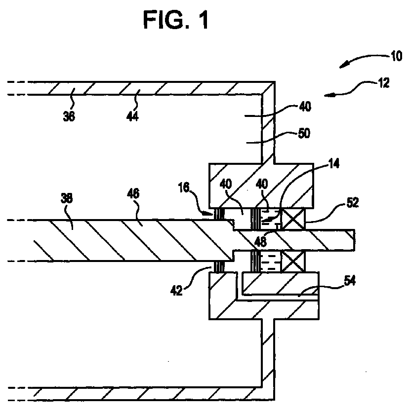
- Figure 1 is a schematic, cross-sectional, side-elevational view of a portion of a hydrogen-cooled electrical generator including two brush seals;
- Figure 2 is a schematic, front-elevational view of a brush seal segment of one of the brush seals of Figure 1, and
- Figure 3 is a view of the brush seal segment of Figure 2 taken along lines 3-3 of Figure 2.
-
- Referring now to the drawings, Figure 1 schematically shows an embodiment of the present invention as a portion of a machine 10 (which is a rotary machine 12) having two
brush seals brush seals 14 shown in greater detail in Figures 2 and 3. It is understood thatbrush seal 16 is similar or generally identical tobrush seal 14, and that the description ofbrush seal 14 given below serves also as a description ofbrush seal 16. In one example, as shown in Figure 1, therotary machine 12 is an electric generator and specifically a hydrogen-cooled electric generator. In other examples, without limitation, therotary machine 12 is a centrifugal compressor, a steam turbine (including a turbine portion thereof) used by a power utility company, or a gas turbine (including a compressor portion or a turbine portion thereof) used as an aircraft engine or used by a power utility company. Such other examples have been omitted from the drawings. It is noted that the invention is not limited to an association with a rotary machine and can be associated with any machine experiencing a fluid pressure drop during machine operation. One example, without limitation, of a non-rotary machine is a linearly-reciprocating machine. It is further noted that the invention is not limited to being expressed as a machine and can also be expressed as a brush seal for a machine. The brush seal is not limited to a moving or rotating portion of the machine and can be employed between two components having no relative motion or relative rotation. - A first expression of the embodiment of the invention shown in Figures 1-3 is a
brush seal 14 for reducing leakage of a fluid across a pressure drop in amachine 10. For purposes of describing the invention, it is understood that the terminology "brush seal" includes, without limitation, a segment of a brush seal when such brush seal is manufactured in segments which are arrayed together to form the complete brush seal Thebrush seal 14 includes abristle holder 18 attachable to themachine 10 and filament-yarn bristles 20 secured to thebristle holder 18. A filament-yarn bristle 20 is defined as a bristle consisting of, or consisting essentially of, afilament 22 supplied to a brush-seal manufacturer together withother filaments 22 in the form of ayarn bristles 20 has a diameter of less than 0.001 inch (and in one example has a diameter of generally 0.00056 inch), a yarn 24-30 contains from 1,000 to 2,000bristles 20, and abrush seal 14 contains between one and hundreds of yarns 24-30. In one construction, thebristles 20 are non-metallic bristles and arefilaments 22 of an aramid filament yarn. An exemplary aramid filament yarn is a KEVLAR® (trademark of DuPont) aramid filament yarn. Other examples of filament yarns include, without limitation, nylon, polyester, and fluorocarbon filament yarns. In one design, each of thebristles 20 has afirst end 32 and asecond end 34, wherein each of thebristles 20 is secured to thebristle holder 18 proximate thefirst end 32, and wherein thesecond end 34 is a free end.. Typically, thebristles 20 have a packing density of greater than 100,000 filaments per inch (and in one example has a packing density of generally 272,000 filaments per inch). - A second expression of the embodiment of the invention shown in Figures 1-3 is a
brush seal 14 for reducing leakage of a fluid across a pressure drop in amachine 10. Thebrush seal 14 includes abristle holder 18 attachable to themachine 10. Thebrush seal 14 also includes a plurality of yarns 24-30, wherein each of the yarns 24-30 consists essentially of (or consists of) a multiplicity offilaments 22, wherein each of thefilaments 22 defines abristle 20, and wherein each of thebristles 20 is secured to thebristle holder 18. For purposes of describing the invention, it is understood that the terminology "plurality of yarns" includes, without limitation, a plurality of shorter yarn segments cut from one or more longer yarns. In one application, thebrush seal 14 contains at least fifty yarns (only four yarns 24-30 being shown for clarity in Figure 2). In an exemplary design, each of thefilaments 22 consists essentially of, or consists of, an aramid filament such as a KEVLAR® (trademark of DuPont) aramid filament, and each of the yarns 24-30 consists of between 1,000 and 2,000filaments 22. In this design, each of thefilaments 22 has a diameter of less than 0.001 inch, and thefilaments 22 have a packing density of greater than 100,000 filaments per inch. For this design, each of thebristles 20 has afirst end 32 and asecond end 34, wherein each of thebristles 20 is secured to the bristleholder 18 proximate thefirst end 32, and wherein thesecond end 34 is a free end. - In a third expression of the invention shown in Figures 1-3, a
machine 10 includes afirst component 36, asecond component 38, a fluid 40, and abrush seal 14. Thesecond component 38 is spaced apart from thefirst component 36 to define agap 42 between the first andsecond components gap 42, wherein the fluid 40 has a pressure drop generally transverse to thegap 42, and wherein the pressure drop is generated during operation of themachine 10. It is noted that the pressure drop can be generated by the machine itself or can be generated independently of the machine. - The
brush seal 14 includes a bristleholder 18 attachable to themachine 10 and filament-yarn bristles 20 secured to the bristleholder 18. A filament-yarn bristle 20 is defined as a bristle consisting of, or consisting essentially of, afilament 22 supplied to a brush-seal manufacturer together withother filaments 22 in the form of ayarn bristles 20 has a diameter of less than 0.001 inch, a yarn 24-30 contains from 1,000 to 2,000bristles 20, and abrush seal 14 contains between one and hundreds of yarns 24-30. In one construction, thebristles 20 arefilaments 22 of an aramid filament yarn. An exemplary aramid filament yarn is a KEVLAR® (trademark of DuPont) aramid filament yarn. Other examples of filament yarns include, without limitation, nylon, polyester, and fluorocarbon filament yarns. In one design, each of thebristles 20 has afirst end 32 and asecond end 34, wherein each of thebristles 20 is secured to the bristleholder 18 proximate thefirst end 32, and wherein thesecond end 34 is a free end.. Typically, thebristles 20 have a packing density of greater than 100,000 filaments per inch. - In a fourth expression of the invention shown in Figures 1-3, a
rotary machine 12 includes astator 44, arotor 46, a fluid 40, and abrush seal 14. Therotor 46 is generally coaxially aligned with thestator 44 and is radially spaced apart from thestator 44 to define agap 42 between thestator 44 and therotor 46. Typically, thestator 44 circumferentially surrounds therotor 46, as seen in Figure 1, but certain applications require the rotor to circumferentially surround the stator, as is known to those skilled in the art. The fluid 40 is disposed in thegap 42, wherein the fluid 40 has a pressure drop generally transverse to thegap 42, and wherein the pressure drop is generated during operation of themachine 10. - The
brush seal 14 includes a bristleholder 18 attachable to thestator 44 of therotary machine 12. Thebrush seal 14 also includes a plurality of yarns 24-30, wherein each of the yarns 24-30 consists essentially of (or consists of) a multiplicity offilaments 22, wherein each of thefilaments 22 defines abristle 20, and wherein each of thebristles 20 is secured to the bristleholder 18. In one application, thebrush seal 14 contains at least fifty yarns (only four yarns 24-30 being shown for clarity in Figure 2). In an exemplary design, each of thefilaments 22 consists essentially of, or consists of, an aramid filament such as a KEVLAR® (trademark of DuPont) aramid filament, and each of the yarns 24-30 consists of between 1,000 and 2,000filaments 22. In this design, each of thefilaments 22 has a diameter of less than 0.001 inch, and thefilaments 22 have a packing density of greater than 100,000 filaments per inch.. For this design, each of thebristles 20 has afirst end 32 and asecond end 34, wherein each of thebristles 20 is secured to the bristleholder 18 proximate thefirst end 32, and wherein thesecond end 34 is a free end which extends generally towards therotor 46. Thesecond end 34 is disposed proximate therotor 46, and in some applications is disposed to just touch therotor 46. Typically, thebristles 20 are canted at an angle, such as the generally forty-five degree angle shown in Figure 2, with such canting being known to the artisan. to minimize interference with therotor 46 if therotor 46 is imagined as present and rotating counterclockwise in Figure 2. - In one design, the
stator 44 is an electric-generator stator, and therotor 46 is an electric-generator rotor. Here,brush seal 14 is for reducing the leakage of a fluid 40 which isliquid oil 48. In a particular refinement of this design, thestator 44 is a hydrogen-cooled electric-generator stator, and therotor 46 is a hydrogen-cooled electric-generator rotor. Here, brush seal 16 (the other brush seal shown in Figure 1) is for reducing the leakage of a fluid 40 which isgaseous hydrogen 50. Arotary machine 12 which is a hydrogen-cooled electric generator has pressurizedgaseous hydrogen 50 present for cooling purposes in that portion of thegap 42 which is to the left ofbrush seal 16 as viewed in Figure 1. The pressure drop of thegaseous hydrogen 50 is from left to right acrossbrush seal 16 as viewed in Figure 1. To prevent anygaseous hydrogen 50 which leaks pastbrush seal 16 from leaking out of therotary machine 12, a more highly-pressurizedliquid oil 48 is introduced (at an entry point not visible in Figure 1) in that portion of thegap 42 which is betweenbrush seal 14 andbearing 52. The pressure drop of theliquid oil 48 is from right to left acrossbrush seal 14 as viewed in Figure 1. Any leaked gaseous hydrogen and liquid oil is extracted from therotary machine 12 throughconduit 54, is separated (not shown), and recycled back into therotary machine 12. Brush seals 14 and/or 16 can be used in other applications such as, without limitation, in a gap between a stator and a rotor (including a tip of a rotor blade) of any compressor and/or turbine portion of an aircraft gas turbine engine or any turbine portion of a steam turbine or any compressor and/or turbine portion of a gas turbine of a power utility company. - One method for making Applicants'
brush seal 10, with its filament-yarn bristles 20, includes cutting a long yarn into shorter, equal-sized yarns (which can also be referred to as yarn segments), wrapping the yarns around a core wire, and clamping the wrapped yarns. Another method includes clamping the yarns between a front plate and a back plate of a bristle holder and then using a high temperature epoxy or other adhesive to join together the yarns and the front and back plates. An exemplary method, whose results are shown in Figures 2-3, includes obtaining a weldablefront plate 56 of abristle holder 18 having astep 58, obtaining aweldable back plate 60 of abristle holder 18 having astep 62 matching thestep 58 of thefront plate 56, clamping the yarns 24-30 between the matchedsteps back plates weldment 64 is spaced apart from the first ends 32 of thebristles 20. - Several benefits and advantages are derived from the invention. Using aramid filaments for the
bristles 20 of abrush seal 14 for amachine 10 results inbristles 20 of smaller diameter resulting in greatly increased bristle packing densities which should significantly reduce leakage. Using a yarn 24-30 of filaments 22 (such as aramid filaments) allows abrush seal 14 of small-diameter bristles 20 to be constructed since it is virtually impossible to handle and secure individual small-diameter aramid filaments to a bristleholder 18. One example of an aramid filament yarn is a KEVLAR® (trademark of DuPont) aramid filament yarn. It is noted that making known metal wire or ceramic wire bristles of smaller diameter would result in bristles that would easily break during usage. When themachine 10 is arotary machine 12, and therotary machine 12 is a hydrogen-cooled electric generator, having smaller diameter bristles results in higher bristle packing densities which should reduce the capillary effect of large diameter bristles to wick the liquid oil acrossbrush seal 16 instead of having that brush seal reduce fluid leakage. It is noted that there is no capillary effect for a gaseous fluid because of the gas turbulence effect which impedes the fluid leakage, as can be appreciated by those skilled in the art. Other benefits include Applicants' bristles being non electrical conductors so that Applicants' brush seal does not require the electrical insulation needed by conventional metal-wire brush seals to insulate them from the stator to prevent unwanted electrical discharge between the rotor and the stator of an electric generator. Applicants' brush seal should save generally one-third the cost of a conventional metal-wire brush seals. - Applicants conducted experiments in a test rig to simulate conditions in an electric generator with the fluid being only oil. The distance between the front plate and the free ends of the bristles was generally 0.300 inch, the distance between the back plate and the free ends of the bristles was 0.030 inch, and the distance between the front and back plates was 0.110 inch. Static test results showed Applicants' brush seal having KEVLAR® (trademark of DuPont) aramid-yarn bristles reduced leakage more than fifty percent compared to a conventional highly-packed metal-bristle brush seal. Preliminary dynamic (i.e., rotating) test results showed Applicants' brush seal having twice the leakage of the conventional brush seal because Applicants' brush seal was made without adequate bristle stiffness wherein such bristles suffered hydrodynamic lift-off. Engineering analysis indicates hydrodynamic lift-off is a problem in a liquid (such as oil) but is not a problem in a gas (such as air), and without hydrodynamic lift-off, dynamic seal behavior should approach static seal behavior. Therefore, it is expected that leakage of a stiffer Applicants' brush seal in oil should be only half the leakage of the conventional brush seal. Applicants plan to dynamically retest their brush seal in oil after increasing bristle stiffness by reducing the distance between the front plate and the free ends of the bristles and/or by increasing the thickness of the brush seal by adding more bristles by increasing the distance between the front and back plates. Applicants also plan static and dynamic tests of their brush seal in air wherein engineering analysis predicts reduced static and dynamic leakage over conventional brush seals.
- For the sake of good order, various features of the invention are set out in the following clauses:-
- 1. A brush seal for reducing leakage of a fluid across a pressure drop in a
machine, said brush seal comprising:
- a) a bristle holder attachable to said machine; and
- b) filament-yarn bristles secured to said bristle holder.
- 2. The brush seal of clause 1, wherein each of said bristles has a diameter of less than 0.001 inch.
- 3. The brush seal of clause 1, wherein said bristles are filaments of an aramid filament yarn.
- 4. The brush seal of clause 1, wherein each of said bristles has a first end and a second end, and wherein each of said bristles is secured to said bristle holder proximate said first end, and wherein said second end is a free end
- 5. The brush seal of clause 1, wherein said bristles have a packing density of greater than 100,000 filaments per inch.
- 6. A brush seal for reducing leakage of a fluid across a pressure drop in a
machine, said brush seal comprising:
- a) a bristle holder attachable to said machine; and
- b) a plurality of yarns, each of said yarns consisting essentially of a multiplicity of filaments, each of said filaments defining a bristle, each of said bristles secured to said bristle holder.
- 7. The brush seal of clause 6, wherein each of said bristles has a diameter of less than 0.001 inch.
- 8. The brush seal of clause 7, wherein said bristles are filaments of an aramid filament yarn.
- 9. The brush seal of clause 8, wherein each of said bristles has a first end and a second end, and wherein each of said bristles is secured to said bristle holder proximate said first end, and wherein said second end is a free end.
- 10. The brush seal of clause 9, wherein said bristles have a packing density of greater than 100,000 filaments per inch.
- 11. A machine comprising:
- a) a first component;
- b) a second component spaced apart from said first component to define a gap between said first and second components;
- c) a fluid in fluid communication with said gap, wherein said fluid has a pressure drop generally transverse to said gap, and wherein said pressure drop is generated during operation of said machine; and
- d) a brush seal including:
- a) a bristle holder attached to said first component; and
- b) filament-yarn bristles secured to said bristle holder.
- 12. The machine of clause 11, wherein each of said bristles has a diameter of less than 0.001 inch.
- 13. The machine of clause 11, wherein said bristles are filaments of an aramid filament yarn.
- 14. The machine of clause 11, wherein each of said bristles has a first end and a second end, wherein each of said bristles is secured to said bristle holder proximate said first end, and wherein said second end extends generally towards said second component.
- 15. The machine of
clause 14, wherein said bristles are filaments of an aramid filament yarn, and wherein each of said bristles has a diameter less than 0.006 inch. - 16. A rotary machine comprising:
- a) a stator;
- b) a rotor generally coaxially aligned with said stator and radially spaced apart from said stator to define a gap between said stator and said rotor;
- c) a fluid disposed in said gap, wherein said fluid has a pressure drop generally transverse to said gap, and wherein said pressure drop is generated during operation of said rotary machine; and
- d) a brush seal including:
- a) a bristle holder attachable to said stator; and
- b) a plurality of yarns, each of said yarns consisting essentially of a multiplicity of filaments, each of said filaments defining a bristle, each of said bristles secured to said bristle holder.
- 17. The rotary machine of
clause 16, wherein each of said filaments consists essentially of an aramid filament. - 18. The rotary machine of clause 17, wherein each of said bristles has a first end and a second end, wherein each of said bristles is secured to said bristle holder proximate said first end, and wherein said second end extends generally towards said rotor.
- 19. The rotary machine of
clause 18, wherein said stator is an electric-generator stator, wherein said rotor is an electric-generator rotor, and wherein said fluid is liquid oil. - 20. The rotary machine of
clause 18, wherein said stator is a hydrogen-cooled electric-generator stator, wherein said rotor is a hydrogen-cooled electric-generator rotor, and wherein said fluid is gaseous hydrogen. -
Claims (10)
- A brush seal for reducing leakage of a fluid across a pressure drop in a machine, said brush seal comprising:a) a bristle holder attachable to said machine; andb) filament-yarn bristles secured to said bristle holder.
- A brush seal for reducing leakage of a fluid across a pressure drop in a machine, said brush seal comprising:a) a bristle holder attachable to said machine; andb) a plurality of yarns, each of said yarns consisting essentially of a multiplicity of filaments, each of said filaments defining a bristle, each of said bristles secured to said bristle holder 2. The brush seal of claim 1, wherein each of said bristles has a diameter of less than 0.001 inch.
- The brush seal of claim 1 or 2, wherein each of said bristles has a diameter less than 0.006 inch.
- The brush seal of claim 3 wherein each of said bristles has a diameter of less than 0.001 inch.
- The brush seal of any preceding claim, wherein said bristles are filaments of an aramid filament yarn.
- The brush seal of any preceding claim, wherein each of said bristles has a first end and a second end, and wherein each of said bristles is secured to said bristle holder proximate said first end, and wherein said second end is a free end
- The brush seal of any preceding claim, wherein said bristles have a packing density of greater than 100,000 filaments per inch.
- A machine comprising:a) a first component;b) a second component spaced apart from said first component to define a gap between said first and second components;c) a fluid in fluid communication with said gap, wherein said fluid has a pressure drop generally transverse to said gap, and wherein said pressure drop is generated during operation of said machine; andd) a brush seal as claimed in any preceding claim:
- The machine of claim 8 when appendant directly or indirectly to claim 6, wherein said second end extends generally towards said second component.
- The machine of claim 8 wherein the machine is a rotary machine the first component is a stator; and the second component is a rotor generally coaxially aligned with said stator and radially spaced apart from said stator to define a gap between said stator and said rotor.
Applications Claiming Priority (4)
| Application Number | Priority Date | Filing Date | Title |
|---|---|---|---|
| US14504999P | 1999-07-22 | 1999-07-22 | |
| US145049P | 1999-07-22 | ||
| US505805 | 2000-02-17 | ||
| US09/505,805 US6406027B1 (en) | 1999-07-22 | 2000-02-17 | Brush seal and machine having a brush seal |
Publications (3)
| Publication Number | Publication Date |
|---|---|
| EP1070888A2 true EP1070888A2 (en) | 2001-01-24 |
| EP1070888A3 EP1070888A3 (en) | 2002-08-28 |
| EP1070888B1 EP1070888B1 (en) | 2008-02-20 |
Family
ID=26842609
Family Applications (1)
| Application Number | Title | Priority Date | Filing Date |
|---|---|---|---|
| EP00306178A Expired - Lifetime EP1070888B1 (en) | 1999-07-22 | 2000-07-20 | Brush seal and machine having a brush seal |
Country Status (4)
| Country | Link |
|---|---|
| US (1) | US6406027B1 (en) |
| EP (1) | EP1070888B1 (en) |
| JP (1) | JP5150021B2 (en) |
| DE (1) | DE60038076T2 (en) |
Cited By (5)
| Publication number | Priority date | Publication date | Assignee | Title |
|---|---|---|---|---|
| EP1696155A2 (en) | 2005-02-25 | 2006-08-30 | Kabushiki Kaisha Toshiba | Brush seal assembly |
| EP1290366B1 (en) * | 2000-10-17 | 2006-11-02 | General Electric Company | Ventilated trickle seal |
| EP1995465A1 (en) * | 2007-05-24 | 2008-11-26 | General Electric Company | Barrier sealing system for centrifugal compressors |
| WO2009010040A1 (en) | 2007-07-14 | 2009-01-22 | Mtu Aero Engines Gmbh | Sealing device for a cooling agent supply on a rotating spindle and machine tool comprising such a sealing device |
| WO2011106118A1 (en) * | 2010-02-26 | 2011-09-01 | General Electric Company | Non-metallic bruch seal |
Families Citing this family (28)
| Publication number | Priority date | Publication date | Assignee | Title |
|---|---|---|---|---|
| US6880829B1 (en) * | 2000-11-06 | 2005-04-19 | Advanced Components & Materials, Inc. | Compliant brush shroud assembly for gas turbine engine compressors |
| JP4944312B2 (en) * | 2001-06-29 | 2012-05-30 | イーグル工業株式会社 | Brush seal device |
| JP3611811B2 (en) * | 2001-08-22 | 2005-01-19 | ティー・アンド・エム株式会社 | SEALING MATERIAL FOR HIGH-SPEED ROTATING BODY, USE THEREOF, AND DEVELOPING DEVICE |
| US7052015B2 (en) * | 2002-08-06 | 2006-05-30 | United Technologies Corporation | Cooling arrangement for brush seal |
| JPWO2004044465A1 (en) | 2002-11-13 | 2006-03-16 | 株式会社東芝 | Rotating electric machine |
| US20040256807A1 (en) * | 2003-06-23 | 2004-12-23 | Nitin Bhate | Retrofittable non-metallic brush seal assembly |
| DE10337867B4 (en) * | 2003-08-18 | 2020-04-23 | MTU Aero Engines AG | Brush seal |
| US6896482B2 (en) * | 2003-09-03 | 2005-05-24 | General Electric Company | Expanding sealing strips for steam turbines |
| US20080284107A1 (en) * | 2004-05-04 | 2008-11-20 | Flaherty Andrew L | Ceramic Brush Seals |
| US7432620B2 (en) * | 2005-05-24 | 2008-10-07 | Siemens Power Generation, Inc. | Seal assembly for a hydrogen-cooled electric power generator with interface impervious to location of plant piping |
| US7255352B2 (en) * | 2005-09-29 | 2007-08-14 | General Electric Company | Pressure balanced brush seal |
| US7653993B2 (en) * | 2005-09-29 | 2010-02-02 | General Electric Company | Method of manufacturing a brush seal for sealing between stationary and rotary components |
| US7565729B2 (en) * | 2006-03-17 | 2009-07-28 | General Electric Company | Methods of manufacturing a segmented brush seal for sealing between stationary and rotary components |
| US20080001363A1 (en) * | 2006-06-28 | 2008-01-03 | General Electric Company | Brush sealing system and method for rotary machines |
| NO325031B1 (en) * | 2006-07-04 | 2008-01-21 | Ge Energy Norway As | Hydro Turbine |
| DE102006034483A1 (en) * | 2006-07-21 | 2008-01-24 | Alstom Technology Ltd. | Regenerative air preheater with brush seal |
| US20080128995A1 (en) * | 2006-12-04 | 2008-06-05 | General Electric | Brush sealing with potting compound for rotary mechanisms |
| US20090302543A1 (en) * | 2008-06-09 | 2009-12-10 | General Electric Company | Sealing systems for rotary machines and methods for modification |
| US20100270747A1 (en) * | 2009-04-24 | 2010-10-28 | General Electric Company | Non-metallic brush seal |
| US8388313B2 (en) * | 2009-11-05 | 2013-03-05 | General Electric Company | Extraction cavity wing seal |
| US8872055B2 (en) * | 2011-04-12 | 2014-10-28 | Fastrax Industries, Inc. | Non-contact rail heater with insulating skirt |
| JP5092036B2 (en) * | 2011-04-25 | 2012-12-05 | 株式会社東芝 | Liquid shaft seal device and rotating electric machine using the shaft seal device |
| US8366115B2 (en) | 2011-06-30 | 2013-02-05 | United Technologies Corporation | Repairable double sided brush seal |
| GB201115773D0 (en) * | 2011-09-13 | 2011-10-26 | Rolls Royce Plc | Brush seal |
| US10400896B2 (en) | 2014-08-28 | 2019-09-03 | United Technologies Corporation | Dual-ended brush seal assembly and method of manufacture |
| US10428953B2 (en) | 2016-02-25 | 2019-10-01 | United Technologies Corporation | C-seal backed brush seal with a compressible core |
| US9845884B2 (en) | 2016-03-17 | 2017-12-19 | United Technologies Corporation | Brush seal with single-layer mixed-diameter bristle pack |
| US10563771B2 (en) * | 2016-04-07 | 2020-02-18 | United Technologies Corporation | Wire mesh brush seal windage cover |
Family Cites Families (19)
| Publication number | Priority date | Publication date | Assignee | Title |
|---|---|---|---|---|
| GB2070700B (en) * | 1980-03-01 | 1983-10-05 | Rolls Royce | Gas turbine seals |
| US4352034A (en) * | 1980-12-22 | 1982-09-28 | General Electric Company | Stator core with axial and radial cooling for dynamoelectric machines wth air-gap stator windings |
| GB2111607B (en) * | 1981-12-08 | 1985-09-18 | Rolls Royce | Bearing chamber pressurisation system for a machine |
| DE3429708C1 (en) * | 1984-08-11 | 1986-01-02 | MTU Motoren- und Turbinen-Union München GmbH, 8000 München | Brush seal |
| CH673729A5 (en) * | 1984-10-04 | 1990-03-30 | Mitsubishi Electric Corp | |
| GB8504331D0 (en) * | 1985-02-20 | 1985-03-20 | Rolls Royce | Brush seals |
| DE3507638A1 (en) * | 1985-03-05 | 1986-09-18 | MTU Motoren- und Turbinen-Union München GmbH, 8000 München | BRUSH SEAL WITH A SPECIAL ARRANGEMENT OF BRUSH ELEMENTS TO IMPROVE OPERATING BEHAVIOR BY DEFLECTION IN THE PRESSURE DIRECTION |
| GB2198195B (en) * | 1986-12-06 | 1990-05-16 | Rolls Royce Plc | Brush seal |
| US4989886A (en) * | 1988-12-30 | 1991-02-05 | Textron Inc. | Braided filamentary sealing element |
| GB8907695D0 (en) * | 1989-04-05 | 1989-05-17 | Cross Mfg Co | Seals |
| FR2690493B1 (en) * | 1992-04-23 | 1996-10-25 | Snecma | BRUSHED ANNULAR JOINT. |
| US5351971A (en) * | 1993-05-21 | 1994-10-04 | Eg&G Sealol, Inc. | Brush seal device having a floating backplate |
| US5425543A (en) * | 1993-09-17 | 1995-06-20 | Buckshaw; Dennis J. | Seal assembly for rotating shaft |
| US5678898A (en) | 1995-04-17 | 1997-10-21 | General Electric Company | Method for making a brush seal |
| US5613829A (en) | 1996-05-03 | 1997-03-25 | General Electric Company | Gas turbine subassembly having a brush seal |
| EP0834688B1 (en) * | 1996-10-02 | 2003-10-22 | MTU Aero Engines GmbH | Brushseal |
| US5961280A (en) | 1997-09-12 | 1999-10-05 | General Elecgtric Company | Anti-hysteresis brush seal |
| US5961125A (en) | 1997-10-02 | 1999-10-05 | General Electric Company | Brush seal for use on rough rotating surfaces |
| US5941685A (en) | 1997-10-14 | 1999-08-24 | General Electric Company | Brush seal for use on bumpy rotating surfaces |
-
2000
- 2000-02-17 US US09/505,805 patent/US6406027B1/en not_active Expired - Lifetime
- 2000-07-19 JP JP2000218143A patent/JP5150021B2/en not_active Expired - Lifetime
- 2000-07-20 EP EP00306178A patent/EP1070888B1/en not_active Expired - Lifetime
- 2000-07-20 DE DE60038076T patent/DE60038076T2/en not_active Expired - Lifetime
Non-Patent Citations (1)
| Title |
|---|
| None |
Cited By (8)
| Publication number | Priority date | Publication date | Assignee | Title |
|---|---|---|---|---|
| EP1290366B1 (en) * | 2000-10-17 | 2006-11-02 | General Electric Company | Ventilated trickle seal |
| EP1696155A2 (en) | 2005-02-25 | 2006-08-30 | Kabushiki Kaisha Toshiba | Brush seal assembly |
| EP1696155A3 (en) * | 2005-02-25 | 2006-11-02 | Kabushiki Kaisha Toshiba | Brush seal assembly |
| EP1995465A1 (en) * | 2007-05-24 | 2008-11-26 | General Electric Company | Barrier sealing system for centrifugal compressors |
| RU2467210C2 (en) * | 2007-05-24 | 2012-11-20 | Дженерал Электрик Компани | Rotary machine (versions) |
| WO2009010040A1 (en) | 2007-07-14 | 2009-01-22 | Mtu Aero Engines Gmbh | Sealing device for a cooling agent supply on a rotating spindle and machine tool comprising such a sealing device |
| US8500128B2 (en) | 2007-07-14 | 2013-08-06 | Mtu Aero Engines Gmbh | Sealing device for a cooling agent supply on a rotating spindle and machine tool comprising such a sealing device |
| WO2011106118A1 (en) * | 2010-02-26 | 2011-09-01 | General Electric Company | Non-metallic bruch seal |
Also Published As
| Publication number | Publication date |
|---|---|
| JP5150021B2 (en) | 2013-02-20 |
| JP2001090842A (en) | 2001-04-03 |
| EP1070888A3 (en) | 2002-08-28 |
| US6406027B1 (en) | 2002-06-18 |
| DE60038076D1 (en) | 2008-04-03 |
| DE60038076T2 (en) | 2009-03-05 |
| EP1070888B1 (en) | 2008-02-20 |
Similar Documents
| Publication | Publication Date | Title |
|---|---|---|
| EP1070888B1 (en) | Brush seal and machine having a brush seal | |
| CA2282006C (en) | Brush seal and rotary machine including such brush seal | |
| US20040000760A1 (en) | Multi-core brush seal assembly for rotary machines | |
| US5961280A (en) | Anti-hysteresis brush seal | |
| US5941685A (en) | Brush seal for use on bumpy rotating surfaces | |
| US9926800B2 (en) | Brush seal | |
| JPH11230361A (en) | Brush seal | |
| EP0979963B1 (en) | Brush seal segment | |
| US20100196139A1 (en) | Leakage flow minimization system for a turbine engine | |
| JP2003106105A (en) | Shaft sealing mechanism and turbine | |
| CN101311549A (en) | Barrier sealing system for centrifugal compressors | |
| CA2744830A1 (en) | Brush seal | |
| CN103477031B (en) | Low pressure cooling seal system for a gas turbine engine | |
| US20040223844A1 (en) | Method and apparatus to facilitate sealing within turbines | |
| US9322287B2 (en) | Brush seal for turbine | |
| JP2009296875A (en) | Rotary machine sealing system and its modification method | |
| US20100275574A1 (en) | Borescope plug with bristles | |
| US20170022837A1 (en) | Aspirating seal assembly and method of assembling | |
| US6612581B2 (en) | Brush seal coil for rotary machinery and method of retrofitting | |
| US5961125A (en) | Brush seal for use on rough rotating surfaces | |
| CN103184902B (en) | Compliance plate-like sealing member and the method for assembling rotating machinery for rotating machinery | |
| US20150001809A1 (en) | Brush seal | |
| US8632075B2 (en) | Seal assembly and method for flowing hot gas in a turbine | |
| EP1070887A2 (en) | Brush seal having secured bristles | |
| CN204627758U (en) | Sealing component and gas turbine |
Legal Events
| Date | Code | Title | Description |
|---|---|---|---|
| PUAI | Public reference made under article 153(3) epc to a published international application that has entered the european phase |
Free format text: ORIGINAL CODE: 0009012 |
|
| AK | Designated contracting states |
Kind code of ref document: A2 Designated state(s): AT BE CH CY DE DK ES FI FR GB GR IE IT LI LU MC NL PT SE |
|
| AX | Request for extension of the european patent |
Free format text: AL;LT;LV;MK;RO;SI |
|
| PUAL | Search report despatched |
Free format text: ORIGINAL CODE: 0009013 |
|
| AK | Designated contracting states |
Kind code of ref document: A3 Designated state(s): AT BE CH CY DE DK ES FI FR GB GR IE IT LI LU MC NL PT SE |
|
| AX | Request for extension of the european patent |
Free format text: AL;LT;LV;MK;RO;SI |
|
| 17P | Request for examination filed |
Effective date: 20030228 |
|
| AKX | Designation fees paid |
Designated state(s): CH DE FR GB LI |
|
| 17Q | First examination report despatched |
Effective date: 20030528 |
|
| GRAP | Despatch of communication of intention to grant a patent |
Free format text: ORIGINAL CODE: EPIDOSNIGR1 |
|
| GRAS | Grant fee paid |
Free format text: ORIGINAL CODE: EPIDOSNIGR3 |
|
| GRAA | (expected) grant |
Free format text: ORIGINAL CODE: 0009210 |
|
| AK | Designated contracting states |
Kind code of ref document: B1 Designated state(s): CH DE FR GB LI |
|
| REG | Reference to a national code |
Ref country code: GB Ref legal event code: FG4D |
|
| REG | Reference to a national code |
Ref country code: CH Ref legal event code: EP |
|
| REF | Corresponds to: |
Ref document number: 60038076 Country of ref document: DE Date of ref document: 20080403 Kind code of ref document: P |
|
| REG | Reference to a national code |
Ref country code: CH Ref legal event code: NV Representative=s name: SERVOPATENT GMBH |
|
| ET | Fr: translation filed | ||
| PLBE | No opposition filed within time limit |
Free format text: ORIGINAL CODE: 0009261 |
|
| STAA | Information on the status of an ep patent application or granted ep patent |
Free format text: STATUS: NO OPPOSITION FILED WITHIN TIME LIMIT |
|
| 26N | No opposition filed |
Effective date: 20081121 |
|
| REG | Reference to a national code |
Ref country code: FR Ref legal event code: PLFP Year of fee payment: 17 |
|
| REG | Reference to a national code |
Ref country code: FR Ref legal event code: PLFP Year of fee payment: 18 |
|
| REG | Reference to a national code |
Ref country code: FR Ref legal event code: PLFP Year of fee payment: 19 |
|
| PGFP | Annual fee paid to national office [announced via postgrant information from national office to epo] |
Ref country code: FR Payment date: 20190621 Year of fee payment: 20 |
|
| PGFP | Annual fee paid to national office [announced via postgrant information from national office to epo] |
Ref country code: CH Payment date: 20190624 Year of fee payment: 20 |
|
| PGFP | Annual fee paid to national office [announced via postgrant information from national office to epo] |
Ref country code: DE Payment date: 20190620 Year of fee payment: 20 Ref country code: GB Payment date: 20190624 Year of fee payment: 20 |
|
| REG | Reference to a national code |
Ref country code: CH Ref legal event code: PCAR Free format text: NEW ADDRESS: WANNERSTRASSE 9/1, 8045 ZUERICH (CH) |
|
| REG | Reference to a national code |
Ref country code: DE Ref legal event code: R071 Ref document number: 60038076 Country of ref document: DE |
|
| REG | Reference to a national code |
Ref country code: CH Ref legal event code: PL |
|
| REG | Reference to a national code |
Ref country code: GB Ref legal event code: PE20 Expiry date: 20200719 |
|
| PG25 | Lapsed in a contracting state [announced via postgrant information from national office to epo] |
Ref country code: GB Free format text: LAPSE BECAUSE OF EXPIRATION OF PROTECTION Effective date: 20200719 |