EP1069980B1 - Apparatus for molding plastic caps - Google Patents
Apparatus for molding plastic caps Download PDFInfo
- Publication number
- EP1069980B1 EP1069980B1 EP99911207A EP99911207A EP1069980B1 EP 1069980 B1 EP1069980 B1 EP 1069980B1 EP 99911207 A EP99911207 A EP 99911207A EP 99911207 A EP99911207 A EP 99911207A EP 1069980 B1 EP1069980 B1 EP 1069980B1
- Authority
- EP
- European Patent Office
- Prior art keywords
- plate assembly
- cap
- blades
- fixed plate
- assembly
- Prior art date
- Legal status (The legal status is an assumption and is not a legal conclusion. Google has not performed a legal analysis and makes no representation as to the accuracy of the status listed.)
- Expired - Lifetime
Links
Images




Classifications
-
- B—PERFORMING OPERATIONS; TRANSPORTING
- B29—WORKING OF PLASTICS; WORKING OF SUBSTANCES IN A PLASTIC STATE IN GENERAL
- B29C—SHAPING OR JOINING OF PLASTICS; SHAPING OF MATERIAL IN A PLASTIC STATE, NOT OTHERWISE PROVIDED FOR; AFTER-TREATMENT OF THE SHAPED PRODUCTS, e.g. REPAIRING
- B29C45/00—Injection moulding, i.e. forcing the required volume of moulding material through a nozzle into a closed mould; Apparatus therefor
- B29C45/17—Component parts, details or accessories; Auxiliary operations
- B29C45/40—Removing or ejecting moulded articles
- B29C45/44—Removing or ejecting moulded articles for undercut articles
-
- B—PERFORMING OPERATIONS; TRANSPORTING
- B29—WORKING OF PLASTICS; WORKING OF SUBSTANCES IN A PLASTIC STATE IN GENERAL
- B29C—SHAPING OR JOINING OF PLASTICS; SHAPING OF MATERIAL IN A PLASTIC STATE, NOT OTHERWISE PROVIDED FOR; AFTER-TREATMENT OF THE SHAPED PRODUCTS, e.g. REPAIRING
- B29C45/00—Injection moulding, i.e. forcing the required volume of moulding material through a nozzle into a closed mould; Apparatus therefor
- B29C45/17—Component parts, details or accessories; Auxiliary operations
- B29C45/26—Moulds
- B29C45/2681—Moulds with rotatable mould parts
-
- B—PERFORMING OPERATIONS; TRANSPORTING
- B29—WORKING OF PLASTICS; WORKING OF SUBSTANCES IN A PLASTIC STATE IN GENERAL
- B29L—INDEXING SCHEME ASSOCIATED WITH SUBCLASS B29C, RELATING TO PARTICULAR ARTICLES
- B29L2031/00—Other particular articles
- B29L2031/56—Stoppers or lids for bottles, jars, or the like, e.g. closures
- B29L2031/565—Stoppers or lids for bottles, jars, or the like, e.g. closures for containers
-
- Y—GENERAL TAGGING OF NEW TECHNOLOGICAL DEVELOPMENTS; GENERAL TAGGING OF CROSS-SECTIONAL TECHNOLOGIES SPANNING OVER SEVERAL SECTIONS OF THE IPC; TECHNICAL SUBJECTS COVERED BY FORMER USPC CROSS-REFERENCE ART COLLECTIONS [XRACs] AND DIGESTS
- Y10—TECHNICAL SUBJECTS COVERED BY FORMER USPC
- Y10S—TECHNICAL SUBJECTS COVERED BY FORMER USPC CROSS-REFERENCE ART COLLECTIONS [XRACs] AND DIGESTS
- Y10S425/00—Plastic article or earthenware shaping or treating: apparatus
- Y10S425/058—Undercut
-
- Y—GENERAL TAGGING OF NEW TECHNOLOGICAL DEVELOPMENTS; GENERAL TAGGING OF CROSS-SECTIONAL TECHNOLOGIES SPANNING OVER SEVERAL SECTIONS OF THE IPC; TECHNICAL SUBJECTS COVERED BY FORMER USPC CROSS-REFERENCE ART COLLECTIONS [XRACs] AND DIGESTS
- Y10—TECHNICAL SUBJECTS COVERED BY FORMER USPC
- Y10S—TECHNICAL SUBJECTS COVERED BY FORMER USPC CROSS-REFERENCE ART COLLECTIONS [XRACs] AND DIGESTS
- Y10S425/00—Plastic article or earthenware shaping or treating: apparatus
- Y10S425/809—Seal, bottle caps only
Definitions
- the components of the injection molding machine are initially in the closed position as shown in Figure 9, wherein plastic is injected through the spine (2), gate (2a), and into the cup-shaped cavity of the female mold (12), wherein the configurations of the upper end portions of the core (11) and blades (13), together with the cup-shaped cavity, form the cap (9).
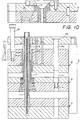
- the movable platen (3) is raised, as shown in Figure 10, and the hydraulic cylinders (5) are extended to raise the movable plate (14a) away from the top surface of the fixed plate assembly (16) while simultaneously moving the movable plate assembly (14) upwardly toward the bottom surface of the fixed plate assembly (16).
Landscapes
- Engineering & Computer Science (AREA)
- Manufacturing & Machinery (AREA)
- Mechanical Engineering (AREA)
- Moulds For Moulding Plastics Or The Like (AREA)
- Encapsulation Of And Coatings For Semiconductor Or Solid State Devices (AREA)
- Casting Or Compression Moulding Of Plastics Or The Like (AREA)
Abstract
Description
- Various apparatus have been proposed for molding plastic caps having hold-down lugs or inclined tabs adapted to engage underneath a shoulder on a container, such as a vial, to hold the cap in a closed, sealed position on the container.
- Before removing the finished cap from the molding apparatus, it is necessary that the tab forming components of the molding apparatus and the molded cap be reoriented relative to each other so that the cap tabs are free from any obstruction in the mold cavity, whereby the finished cap can be stripped from the mold cavity.
- The reorientation of the finished cap and the tab forming components of the molding apparatus relative to each other is usually accomplished by either moving the tab forming components away from the tabs on the finished cap, or rotating the finished cap in a direction away from the tab forming components in the molding apparatus.
- The molding apparatus of the present invention is constructed and arranged to rotate the finished cap relative to the tab forming components in the molding apparatus.
- The apparatus of the present invention for molding plastic caps having inclined tabs and radially inwardly extending ribs comprises, essentially, a conventional injection molding core machine having a fixed platen assembly supporting a core and a movable platen assembly carrying a female mold having a cup-shaped cavity. Fixed and movable plate assemblies are positioned between the platen assemblies and the core extends upwardly through the movable and fixed plate assemblies to the female mold. A plurality of vertically extending blades are secured to one of the movable plate assemblies and are slidably mounted in axial grooves provided on the exterior surface of the core. The upper end portion of the blades are provided with recesses having configurations corresponding to the inclined tabs and radially inwardly extending ribs on the plastic cap.
- A linear drive member is mounted on one of the fixed plate assemblies and a ratchet sleeve is rotatably mounted on one of the movable plate assemblies and extends upwardly coaxially with the linear drive member. The ratchet sleeve is provided with a pair of axially extending, diametrically disposed offset slots which receive transverse pins connected to the linear drive member. The upper peripheral edge of the ratchet sleeve is provided with a plurality of circumferentially spaced teeth between which the plastic, forming the lower edge of the skirt of the cap, flows during the molding operation.
- By this construction and arrangement, when the movable plate assembly carrying the ratchet sleeve moves upwardly, the pin connection between the linear drive member and the ratchet sleeve causes the ratchet sleeve to rotate, whereby the teeth on the end of the ratchet sleeve, engaging the lower edge of the cap skirt, causes the cap to rotate relative to the upper end portions of the blades to thereby move the cap tabs and ribs away from the tab and rib forming recesses prior to stripping the finished cap from the apparatus.
- An apparatus according to US-A-2,583,093 is the basis of the preamble of claim 1. There is disclosed a slot-and-pin-controlled movement of one blade for performing an demoulding sequence. A shaft is prevented from rotation.
- DE 195 38 838 A is showing a plurality of inwardly extending ribs and a plurality of longitudinally extending blades being mounted slidably and rotatably as well as a core prevented from rotation.
- The appended claims characterise the present invention.
-
- Figure 1 is a perspective view of the molding apparatus of the present invention.
- Figure 2 is a perspective view of a vial having a cap thereon molded by the apparatus of the present invention.
- Figure 3 is a sectional, side elevational view of the cap shown in Figure 2, without the dust cover.
- Figure 4 is a perspective view of the cap shown in Figure 3.
- Figure 5 is a bottom plan view of the cap shown in Figure 3.
- Figure 6 is an enlarged, fragmentary, side elevational view of the molding apparatus of the present invention in the closed, cap forming position.
- Figure 7 is a perspective view of the ratchet sleeve and upper end portions of the core and blades employed in the molding machine of the present invention.
- Figure 8 is a view taken along line 8-8 of Figure 9.
- Figure 9 is a view taken along line 9-9 of Figure 1.
- Figure 10, 11, and 12 are sectional, side elevational views illustrating the operation of the molding machine when molding the cap shown in Figure 3.
- Referring to the drawings and, more particularly to Figure 1, the molding apparatus (1) of the present invention comprises a conventional single cavity injection molding machine having a spine (2) mounted and vertically moveable platen assembly (3) and a fixed platen assembly (4) upon which hydraulic cylinders (5) are mounted. The fixed platen assembly (4) and hydraulic cylinders (5) are provided with a suitable housing (6) into which hoses (7) and (8) extend for the supply and exhaust of hydraulic fluid to the cylinders (5).
- The injection molding machine is for molding vial caps (9) shown in Figures 2 to 5, and as disclosed in U.S. 5,718,348. The cap (9) is adapted for sealing a glass vial (10) and is provided with a dust cover (10). The cap has a top wall (9a) and a skirt portion (9b) depending therefrom. The top wall (9a) is provided with an opening (9c) for holding the dust cover (10) thereon. The lower end of the skirt portion (9b) is provided with a plurality of integral, inwardly, and upwardly extending tabs (9d) adapted to engage the bottom surface of a shoulder on the neck of the vial (10) for securing the cap (9) to the vial (10), and a plurality of radially inwardly extending ribs (9e) are integral with the inner wall surface of the skirt (9b), the ribs (9e) being adapted to be inserted between the teeth of a gear finish on the neck of vial (10), to thereby prevent the cap (9) from turning when secured to the vial (10).
- The details of the construction of the apparatus for molding the cap (9) are illustrated in Figures 6 to 9 and comprise a conventional injection molding machine wherein the lower end of a vertically extending core (11) is secured to the fixed platen assembly (4). The upper end portion of the core (11) extends into a female mold (12) having a cup-shaved cavity carried by the movable platen assembly (3). The upper end portion of the core (11) is configured to form the top wall (9a) of the cap and the peripheral portions of the cap skirt (9b) between the tabs (9d) and ribs (9e).
- In order to form the cap tabs (9d) and ribs (9e), a plurality of axially extending blades (13) are slidably mounted in slots 11a (Figure 8) provided on the outer surface of the core (11). The lower ends of the blades (13) are secured to a movable plate assembly (14), and the upper end portions of the blades (13) are provided with recesses (13a and 13b) having configurations corresponding to the cap tabs (9d) and ribs (9e) respectively.
- Figure (9) shows the injection molding machine in the closed position for molding the cap (9) wherein plastic is injected through the spine (2) through a gate (2a) into the cup-shaped cavity of the female mold (12). The upper end portions of the core (11) and blades (13) are spaced slightly radially inwardly from the inner wall of the female mold to provide a clearance into which the plastic flows to form the cap (9).
- Before the finished cap (9) can be removed from the mold (12), it has to be reorientated within the mold (12) to move the tabs (9d) and ribs (9e) out of their respective blade recesses (13a and 13b). To this end, a linear drive member (15) is mounted in a fixed plate assembly (16), and a ratchet sleeve (17) is positioned coaxially within the linear drive member (15) and has its lower end supported on the movable plate assembly (14) and rotatably mounted thereon by suitable bearings (18). The ratchet sleeve (17) extends upwardly through the fixed plate assembly (16) and is rotatably mounted therein by a bearing (19). The ratchet sleeve (17) is provided with a pair of axially extending, diametrically disposed offset slots (17a) which receive transverse pins (20) connected to the linear drive member (15). The upper peripheral edge of the ratchet sleeve (17) is provided with a plurality of circumferentially spaced teeth (17b) between which the plastic, forming the lower edge of the cap skirt, flows during the molding application.
- By this construction and arrangement, when the moveable plate assembly (14) carrying the ratchet sleeve (17) is moved upwardly, the pin connection (20) between the linear drive member (15) and the ratchet sleeve (17) causes the ratchet sleeve (17) to rotate, whereby the teeth (17b) on the end of the ratchet sleeve (17), engaging the lower edge of the cap skirt, causes the cap (9) to rotate relative to the blades (13), to thereby move the cap tabs (9d) and ribs (9e) out of their respective recesses (13a, 13b).
- The upward movement of movable plate assembly (14) is accomplished by the hydraulic cylinders (5) connected at their upper ends to a movable plate (14a) having a depending rod (14b) extending downwardly through the fixed plate assembly (16) and slidably mounted therein. The lower end of the rod (14b) is provided with a spring tensioned telescopic portion (14c), and a friction sleeve (14a) mounted in the movable plate assembly (14). As the hydraulic cylinders (5) are extended, as shown in Figure 10, the movable plate (14a) is pushed upwardly away from the top surface of the fixed plate assembly (16). The rod (14b), carried by the movable plate (14a), pulls the movable plate assembly (14) upwardly until the movable plate assembly (14) engages the bottom surface of the fixed plate assembly (16) as shown in Figure 11. Continued upward movement of the moveable plate (14a), as shown in Figure 12, is accommodated by the extension of the telescopic portion (14c) of the rod (14b).
- To complete the structure of the molding apparatus, suitable guide rods (21,22) extend between the fixed plate assembly (16) and the movable plate (14a), having a stripper (23) mounted therein, and a coolant tube (24) is fixed at its lower end to the fixed platen assembly and extends upwardly into the core (11).
- In the operation of the molding apparatus of the present invention, the components of the injection molding machine are initially in the closed position as shown in Figure 9, wherein plastic is injected through the spine (2), gate (2a), and into the cup-shaped cavity of the female mold (12), wherein the configurations of the upper end portions of the core (11) and blades (13), together with the cup-shaped cavity, form the cap (9). After the plastic has set, the movable platen (3) is raised, as shown in Figure 10, and the hydraulic cylinders (5) are extended to raise the movable plate (14a) away from the top surface of the fixed plate assembly (16) while simultaneously moving the movable plate assembly (14) upwardly toward the bottom surface of the fixed plate assembly (16). Since the blades (13) and ratchet sleeve (17) are mounted on the movable plate assembly (14), they too slide upwardly relative to the core (11) which is mounted on the fixed platen (4). The ratchet sleeve (17) also slides upwardly relative to the linear drive member (15). During this upward movement, the pins (20) on the linear drive member (15) slide in the slots (17a) of the ratchet sleeve (17). Since the first portion of the slot (17a) is axial, as shown schematically in Figure 10, there is no rotation of the ratchet sleeve (17). Continued upward movement of the movable plate assembly (14) and movable plate (14a), as shown in Figure 11, will result in the linear drive member pins (20) sliding in the offset portions of the slots (17a) causing the ratchet sleeve (17) to rotate substantially 60 degrees. Since the teeth (17b) on the end of the ratchet sleeve (17) are connected to the lower peripheral edge of the cap (9), the cap is rotated relative to the blades (13) so that the cap tabs (9d) and ribs (9e) are moved clear of the blade recesses (13a, 13b). The cap (9) is now in position for removal from the molding apparatus which is shown in Figure 12, wherein continued upward movement of the movable plate (14a) causes the stripper (23) to engage the lower edge portion of the cap skirt to thereby push the cap (9) out of engagement with the ratchet sleeve teeth (17b).
- It is to be understood that the form of the invention herewith shown and described is to be taken as a preferred example of the same, and that various changes in the shape, size, and arrangement of parts may be resorted to, without departing from the invention or scope of the subjoined claims.
Claims (5)
- Apparatus for molding a plastic cap (9) having a top wall (9a) and a depending skirt (9b) having a plurality of inwardly and upwardly extending inclined tabs (9d) integral with the lower edge of the skirt and a plurality of radially inwardly extending ribs (9c) integral with the inner wall surface of the skirt, a fixed platen assembly (4), a core (11) secured to said fixed platen assembly, a movable platen assembly (3) spaced from said fixed platen assembly, a female mold (12) having a cup-shaped cavity mounted in said movable platen assembly, said cup-shaped cavity being connected to a supply of flowable plastic material, a movable plate assembly (14) and a fixed plate assembly (16) positioned between the fixed (4) and movable (3) platens, said core (11) extending through the movable and fixed plate assemblies into the cup-shaped cavity of said female mold, characterized by a plurality of longitudinally extending blades (13) slidably mounted on the outer surface of said core (11), a first end of each of said blades being secured to said movable plate assembly (14), a second end of each of said blades extending into the female mold, recesses (13a, 13b) provided in the second end of each of said blades, said recesses having configurations corresponding to the inclined tabs and radially inwardly extending ribs on the cap, said core and blades being spaced inwardly from the wall of said cavity to provide a gap for receiving the flow of plastic material therein to form the cap, a drive member (15) secured to said fixed plate assembly (16), a rotatable driven member (17) mounted on said movable plate assembly (14), said rotatable driven member being operatively connected to said drive member having an end portion engaging the lower peripheral edge of the molded cap skirt in the 21a female mold (12) means (5) for moving the movable plate assembly relative to the fixed plate assembly, whereby the drive member (15) on the fixed plate assembly causes the driven member (17) on the movable plate assembly to rotate, to thereby rotate the molded cap relative to the second end of each of said blades for moving the cap tabs and ribs away from the blade recesses prior to stripping the finished cap from the apparatus, said drive member (15) comprising a cylindrical linear drive member, and said driven member comprising a ratchet sleeve (17) mounted coaxially within the cylindrical drive member (15) and slidably mounted on said core and blades, at least one axially extending offset slot (17a) provided in the side wall of said ratchet sleeve, and at least one pin (20) fixedly mounted into said linear drive member and extending radially therefrom into said slot, whereby upon movement of the movable plate assembly, the pin in the slot causes the ratchet sleeve to rotate.
- Apparatus for molding a plastic cap according to Claim 1, wherein a plurality of circumferentially spaced teeth (17b) are provided on the end portion of the ratchet sleeve (17), said teeth engaging the lower peripheral edge of the molded cap skirt (9b).
- Apparatus for molding a plastic cap according to Claim 2, wherein the movable plate assembly (14) includes first and second plate members positioned on opposite sides of said fixed plate assembly (16), and the means for moving the movable plate assembly relative to the fixed plate assembly comprises at least one hydraulic cylinder (5) connected to the first plate member on one side of said fixed plate assembly, a depending rod (14b) connected to said first plate member and extending through said fixed plate assembly, the end of the rod being connected to the second plate member, whereby upon extension of the hydraulic cylinder (5) the first plate member is moved away from one side of the fixed plate assembly and the second plate member is pulled by said rod (14b) toward the opposite side of said fixed plate assembly (16).
- Apparatus for molding a plastic cap according to Claim 3, wherein the end of the rod (14b) connected to the second plate member is provided with a spring tensioned telescopic portion (14c), whereby when the second plate member abuts said opposite side of the fixed plate assembly (16), the telescopic portion (14c) extends thereby allowing the first plate member to be moved further from the said one side of said fixed plate assembly (16).
- Apparatus according to Claim 4, wherein a stripper (23) is mounted in said first plate member, whereby the stripper removes the finished cap (9) from the second end of each of said blades (13) during said further movement of said first plate member.
Applications Claiming Priority (3)
| Application Number | Priority Date | Filing Date | Title |
|---|---|---|---|
| US09/049,064 US6079973A (en) | 1998-03-27 | 1998-03-27 | Apparatus for molding plastic caps |
| US49064 | 1998-03-27 | ||
| PCT/US1999/005062 WO1999050043A1 (en) | 1998-03-27 | 1999-03-09 | Apparatus for molding plastic caps |
Publications (3)
| Publication Number | Publication Date |
|---|---|
| EP1069980A1 EP1069980A1 (en) | 2001-01-24 |
| EP1069980A4 EP1069980A4 (en) | 2004-04-14 |
| EP1069980B1 true EP1069980B1 (en) | 2006-01-11 |
Family
ID=21957888
Family Applications (1)
| Application Number | Title | Priority Date | Filing Date |
|---|---|---|---|
| EP99911207A Expired - Lifetime EP1069980B1 (en) | 1998-03-27 | 1999-03-09 | Apparatus for molding plastic caps |
Country Status (6)
| Country | Link |
|---|---|
| US (4) | US6079973A (en) |
| EP (1) | EP1069980B1 (en) |
| AT (1) | ATE315463T1 (en) |
| DE (1) | DE69929425T2 (en) |
| TW (1) | TW445204B (en) |
| WO (1) | WO1999050043A1 (en) |
Families Citing this family (20)
| Publication number | Priority date | Publication date | Assignee | Title |
|---|---|---|---|---|
| US6079973A (en) * | 1998-03-27 | 2000-06-27 | Comar, Inc. | Apparatus for molding plastic caps |
| US6287106B1 (en) * | 1999-07-09 | 2001-09-11 | D. Blair Learn | Injection mold cavity and dispensing cap manufactured therein |
| US6592797B2 (en) * | 2001-06-28 | 2003-07-15 | The Tech Group, Inc. | Method and apparatus to reduce galling in a mold device |
| US20050252335A1 (en) * | 2004-05-11 | 2005-11-17 | Harris Corporation | Linear ratchet apparatus |
| US7333057B2 (en) | 2004-07-31 | 2008-02-19 | Harris Corporation | Stacked patch antenna with distributed reactive network proximity feed |
| ITMO20070055A1 (en) * | 2007-02-21 | 2008-08-22 | Sacmi | MOLD DEVICE FOR FORMING OBJECTS |
| JP5258667B2 (en) * | 2009-04-23 | 2013-08-07 | 矢崎総業株式会社 | Housing mold structure, housing molding method, and housing |
| CN101830056B (en) * | 2010-05-21 | 2012-11-14 | 江门敬记塑胶厂有限公司 | Injection mold of formed screw cap ingate |
| ES2371731B1 (en) * | 2010-06-11 | 2012-05-28 | Irumold S.L. | MOLD FOR INJECTED PARTS WITH INTERNAL CONTRASALIDS. |
| US20120107441A1 (en) * | 2010-10-30 | 2012-05-03 | Cheng Uei Precision Industry Co., Ltd. | Mold having push-out structure |
| US8475156B2 (en) * | 2011-03-24 | 2013-07-02 | Cheng Uei Precision Industry Co., Ltd. | Injection mold |
| CN103737868B (en) * | 2013-12-31 | 2016-05-11 | 南烽精密机械(深圳)有限公司 | A kind of mould emptier of plastic bottle cap die and its implementation |
| WO2016131994A1 (en) * | 2015-02-18 | 2016-08-25 | Sna Europe Industries Iberia, S.A. | Mould, part, system and method for objects with grooves or hollows |
| US10695966B2 (en) * | 2016-05-13 | 2020-06-30 | The Procter & Gamble Company | Apparatus for molding hollow workpieces |
| US10322538B2 (en) * | 2016-05-13 | 2019-06-18 | The Procter & Gamble Company | Process for molding hollow workpieces |
| US11052582B1 (en) * | 2018-05-02 | 2021-07-06 | Versevo, Inc. | Collapsible core devices and method for injection molding |
| IT201800009101A1 (en) * | 2018-10-02 | 2020-04-02 | Gefit Spa | APPARATUS AND METHOD OF MANUFACTURING A GUARANTEE CAP FOR BOTTLES |
| GB2580062B (en) * | 2018-12-20 | 2021-01-06 | John Guest International Ltd | A mold and method for molding a body or cap for a connector |
| IT201900004057A1 (en) * | 2019-03-20 | 2020-09-20 | Bisio Progetti Spa | MOLD, INJECTION MOLDING METHOD AND RELEVANT CAP WITH EXTERNAL INTERNAL PORTIONS |
| FR3108550B1 (en) * | 2020-03-24 | 2022-04-08 | Faurecia Interieur Ind | Mold for producing a molded article |
Family Cites Families (19)
| Publication number | Priority date | Publication date | Assignee | Title |
|---|---|---|---|---|
| US2583093A (en) * | 1949-01-26 | 1952-01-22 | Fed Tool Corp | Apparatus for making closures for containers |
| US3584111A (en) * | 1968-10-03 | 1971-06-08 | Owens Illinois Inc | Method and apparatus for molding plastic articles |
| US3737277A (en) * | 1971-07-19 | 1973-06-05 | G Uhlig | Mold structure for molding skirted closures having integral lugs on the inside surface thereof |
| US3730664A (en) * | 1971-11-24 | 1973-05-01 | Eyelet Specialty Co | Mold apparatus for making a closure cap |
| US4019711A (en) * | 1975-11-10 | 1977-04-26 | J & J Tool And Mold Ltd. | Mould for closure caps with intermittent threads undercuts or hold-down lugs |
| US4496302A (en) * | 1982-06-04 | 1985-01-29 | Husky Injection Molding Systems Inc. | Apparatus for molding plastic articles |
| US4592475A (en) * | 1982-12-06 | 1986-06-03 | Charles N. Hannon | Plastic closure with mechanical pilfer-proof |
| US4673158A (en) * | 1984-12-10 | 1987-06-16 | Charles N. Hannon | Apparatus for forming a pilfer proof container closure |
| JP2585601B2 (en) * | 1987-06-05 | 1997-02-26 | 東陶機器株式会社 | Core structure for molding equipment |
| JP2649098B2 (en) * | 1990-06-16 | 1997-09-03 | ファナック株式会社 | Injection molding machine with built-in core drive |
| US5061168A (en) * | 1990-07-09 | 1991-10-29 | Fox Alton L | Modular unscrewing mold apparatus |
| IT1254621B (en) * | 1992-02-21 | 1995-09-28 | WARRANTY CLOSURE FOR BOTTLES AND SIMILAR | |
| US5383780A (en) * | 1993-09-27 | 1995-01-24 | Husky Injection Molding Systems Ltd. | Apparatus for forming threaded molded article |
| US5421717A (en) * | 1994-05-31 | 1995-06-06 | Husky Injection Molding Systems Ltd. | Apparatus for forming threaded molded articles |
| US5565223A (en) * | 1993-09-27 | 1996-10-15 | Husky Injection Molding Systems Ltd. | Apparatus for forming molded article |
| US5403179A (en) * | 1993-10-29 | 1995-04-04 | Ramsey; William C. | Collapsible mold core assembly |
| DE19538838A1 (en) * | 1995-10-19 | 1997-04-24 | Wella Ag | Plastic closure cap moulding tool for forming internal projections and operation of tool |
| DE19724204A1 (en) * | 1997-06-09 | 1998-12-10 | Richard Herbst | Method and device for the injection moulding of a plastic body with an internal thread |
| US6079973A (en) * | 1998-03-27 | 2000-06-27 | Comar, Inc. | Apparatus for molding plastic caps |
-
1998
- 1998-03-27 US US09/049,064 patent/US6079973A/en not_active Expired - Lifetime
-
1999
- 1999-03-09 AT AT99911207T patent/ATE315463T1/en not_active IP Right Cessation
- 1999-03-09 DE DE69929425T patent/DE69929425T2/en not_active Expired - Lifetime
- 1999-03-09 EP EP99911207A patent/EP1069980B1/en not_active Expired - Lifetime
- 1999-03-09 WO PCT/US1999/005062 patent/WO1999050043A1/en not_active Ceased
- 1999-03-26 TW TW088104822A patent/TW445204B/en active
-
2000
- 2000-04-18 US US09/551,048 patent/US6409498B1/en not_active Expired - Lifetime
-
2001
- 2001-10-23 US US10/044,661 patent/US20020086080A1/en not_active Abandoned
-
2003
- 2003-07-30 US US10/631,361 patent/US20040115301A1/en not_active Abandoned
Also Published As
| Publication number | Publication date |
|---|---|
| WO1999050043A1 (en) | 1999-10-07 |
| DE69929425D1 (en) | 2006-04-06 |
| US6409498B1 (en) | 2002-06-25 |
| EP1069980A4 (en) | 2004-04-14 |
| EP1069980A1 (en) | 2001-01-24 |
| US6079973A (en) | 2000-06-27 |
| DE69929425T2 (en) | 2006-08-31 |
| US20040115301A1 (en) | 2004-06-17 |
| TW445204B (en) | 2001-07-11 |
| ATE315463T1 (en) | 2006-02-15 |
| US20020086080A1 (en) | 2002-07-04 |
Similar Documents
| Publication | Publication Date | Title |
|---|---|---|
| US6079973A (en) | Apparatus for molding plastic caps | |
| US5383780A (en) | Apparatus for forming threaded molded article | |
| US4340352A (en) | Hinge exercising mechanism | |
| US6599115B2 (en) | Mold unscrewing mechanism for making threaded articles | |
| DE69600791T2 (en) | SEAMLESS MOLDED RING COLLAR AND METHOD | |
| EP0618857B1 (en) | Process and device for injection moulding plastic pots | |
| DE69705636T2 (en) | INJECTION MOLD FOR PRODUCING A BUCKET WITH SWIVELING HANDLE | |
| EP3455061B1 (en) | Process for molding hollow workpieces | |
| EP0581483B1 (en) | Device for and method of forging a helical gear | |
| US3584111A (en) | Method and apparatus for molding plastic articles | |
| RU2295441C2 (en) | Rotary-type device for manufacture of the articles out of the plastics by the direct pressure | |
| EP3455062B1 (en) | Apparatus for molding hollow workpieces | |
| CN114179304B (en) | Injection mold | |
| WO2009111854A1 (en) | In-mold closing mechanism and method | |
| JP3908332B2 (en) | Method for forming cylindrical body and mold | |
| US3930777A (en) | Plastic u-shaped return conduit and apparatus and method for molding the same | |
| RU2423232C2 (en) | Cap compression moulding machine | |
| CN114407290A (en) | Successive layer injection mold of degradable plastic product | |
| US4174940A (en) | Apparatus for automatically handling a mold for tires with a rigid segmented core | |
| AU2006309262C1 (en) | Method and machine for compression molding closure shells | |
| CN217916579U (en) | Improved oil can cover injection mold | |
| CN219883195U (en) | Processing die convenient to location | |
| CN116766495A (en) | Intelligent injection molding device with consistent stability | |
| CN224046938U (en) | Cover screwing machine capable of switching moving cover and fixed cover | |
| JPS5816842Y2 (en) | Undercut processing equipment for container molding molds |
Legal Events
| Date | Code | Title | Description |
|---|---|---|---|
| PUAI | Public reference made under article 153(3) epc to a published international application that has entered the european phase |
Free format text: ORIGINAL CODE: 0009012 |
|
| 17P | Request for examination filed |
Effective date: 20000906 |
|
| AK | Designated contracting states |
Kind code of ref document: A1 Designated state(s): AT BE CH CY DE DK ES FI FR GB GR IE IT LI LU MC NL PT SE |
|
| A4 | Supplementary search report drawn up and despatched |
Effective date: 20040227 |
|
| RIC1 | Information provided on ipc code assigned before grant |
Ipc: 7B 29C 33/48 B Ipc: 7B 29C 45/44 A |
|
| 17Q | First examination report despatched |
Effective date: 20040507 |
|
| GRAP | Despatch of communication of intention to grant a patent |
Free format text: ORIGINAL CODE: EPIDOSNIGR1 |
|
| GRAS | Grant fee paid |
Free format text: ORIGINAL CODE: EPIDOSNIGR3 |
|
| GRAA | (expected) grant |
Free format text: ORIGINAL CODE: 0009210 |
|
| AK | Designated contracting states |
Kind code of ref document: B1 Designated state(s): AT BE CH CY DE DK ES FI FR GB GR IE IT LI LU MC NL PT SE |
|
| PG25 | Lapsed in a contracting state [announced via postgrant information from national office to epo] |
Ref country code: NL Free format text: LAPSE BECAUSE OF FAILURE TO SUBMIT A TRANSLATION OF THE DESCRIPTION OR TO PAY THE FEE WITHIN THE PRESCRIBED TIME-LIMIT Effective date: 20060111 Ref country code: LI Free format text: LAPSE BECAUSE OF FAILURE TO SUBMIT A TRANSLATION OF THE DESCRIPTION OR TO PAY THE FEE WITHIN THE PRESCRIBED TIME-LIMIT Effective date: 20060111 Ref country code: FI Free format text: LAPSE BECAUSE OF FAILURE TO SUBMIT A TRANSLATION OF THE DESCRIPTION OR TO PAY THE FEE WITHIN THE PRESCRIBED TIME-LIMIT Effective date: 20060111 Ref country code: CH Free format text: LAPSE BECAUSE OF FAILURE TO SUBMIT A TRANSLATION OF THE DESCRIPTION OR TO PAY THE FEE WITHIN THE PRESCRIBED TIME-LIMIT Effective date: 20060111 Ref country code: AT Free format text: LAPSE BECAUSE OF FAILURE TO SUBMIT A TRANSLATION OF THE DESCRIPTION OR TO PAY THE FEE WITHIN THE PRESCRIBED TIME-LIMIT Effective date: 20060111 |
|
| REG | Reference to a national code |
Ref country code: CH Ref legal event code: EP |
|
| REG | Reference to a national code |
Ref country code: IE Ref legal event code: FG4D |
|
| PG25 | Lapsed in a contracting state [announced via postgrant information from national office to epo] |
Ref country code: MC Free format text: LAPSE BECAUSE OF NON-PAYMENT OF DUE FEES Effective date: 20060331 Ref country code: LU Free format text: LAPSE BECAUSE OF NON-PAYMENT OF DUE FEES Effective date: 20060331 |
|
| REF | Corresponds to: |
Ref document number: 69929425 Country of ref document: DE Date of ref document: 20060406 Kind code of ref document: P |
|
| PG25 | Lapsed in a contracting state [announced via postgrant information from national office to epo] |
Ref country code: SE Free format text: LAPSE BECAUSE OF FAILURE TO SUBMIT A TRANSLATION OF THE DESCRIPTION OR TO PAY THE FEE WITHIN THE PRESCRIBED TIME-LIMIT Effective date: 20060411 Ref country code: DK Free format text: LAPSE BECAUSE OF FAILURE TO SUBMIT A TRANSLATION OF THE DESCRIPTION OR TO PAY THE FEE WITHIN THE PRESCRIBED TIME-LIMIT Effective date: 20060411 |
|
| PG25 | Lapsed in a contracting state [announced via postgrant information from national office to epo] |
Ref country code: ES Free format text: LAPSE BECAUSE OF FAILURE TO SUBMIT A TRANSLATION OF THE DESCRIPTION OR TO PAY THE FEE WITHIN THE PRESCRIBED TIME-LIMIT Effective date: 20060422 |
|
| PG25 | Lapsed in a contracting state [announced via postgrant information from national office to epo] |
Ref country code: PT Free format text: LAPSE BECAUSE OF FAILURE TO SUBMIT A TRANSLATION OF THE DESCRIPTION OR TO PAY THE FEE WITHIN THE PRESCRIBED TIME-LIMIT Effective date: 20060612 |
|
| NLV1 | Nl: lapsed or annulled due to failure to fulfill the requirements of art. 29p and 29m of the patents act | ||
| REG | Reference to a national code |
Ref country code: CH Ref legal event code: PL |
|
| ET | Fr: translation filed | ||
| PLBE | No opposition filed within time limit |
Free format text: ORIGINAL CODE: 0009261 |
|
| STAA | Information on the status of an ep patent application or granted ep patent |
Free format text: STATUS: NO OPPOSITION FILED WITHIN TIME LIMIT |
|
| 26N | No opposition filed |
Effective date: 20061012 |
|
| PG25 | Lapsed in a contracting state [announced via postgrant information from national office to epo] |
Ref country code: GR Free format text: LAPSE BECAUSE OF FAILURE TO SUBMIT A TRANSLATION OF THE DESCRIPTION OR TO PAY THE FEE WITHIN THE PRESCRIBED TIME-LIMIT Effective date: 20060412 |
|
| PG25 | Lapsed in a contracting state [announced via postgrant information from national office to epo] |
Ref country code: CY Free format text: LAPSE BECAUSE OF FAILURE TO SUBMIT A TRANSLATION OF THE DESCRIPTION OR TO PAY THE FEE WITHIN THE PRESCRIBED TIME-LIMIT Effective date: 20060111 |
|
| REG | Reference to a national code |
Ref country code: DE Ref legal event code: R082 Ref document number: 69929425 Country of ref document: DE Representative=s name: PATENTANWAELTE WESTPHAL MUSSGNUG & PARTNER, DE |
|
| REG | Reference to a national code |
Ref country code: GB Ref legal event code: 732E Free format text: REGISTERED BETWEEN 20140501 AND 20140507 |
|
| REG | Reference to a national code |
Ref country code: DE Ref legal event code: R082 Ref document number: 69929425 Country of ref document: DE Representative=s name: WESTPHAL, MUSSGNUG & PARTNER PATENTANWAELTE MI, DE Effective date: 20140428 Ref country code: DE Ref legal event code: R082 Ref document number: 69929425 Country of ref document: DE Representative=s name: PATENTANWAELTE WESTPHAL MUSSGNUG & PARTNER, DE Effective date: 20140428 Ref country code: DE Ref legal event code: R081 Ref document number: 69929425 Country of ref document: DE Owner name: COMAR, LLC (N.D.GES. DES STAATES DELAWARE), BU, US Free format text: FORMER OWNER: COMAR, INC., BUENA, N.J., US Effective date: 20140428 Ref country code: DE Ref legal event code: R081 Ref document number: 69929425 Country of ref document: DE Owner name: COMAR, LLC (N.D.GES. DES STAATES DELAWARE), US Free format text: FORMER OWNER: COMAR, INC., BUENA, US Effective date: 20140428 |
|
| REG | Reference to a national code |
Ref country code: FR Ref legal event code: TP Owner name: COMAR LLC, US Effective date: 20140505 |
|
| REG | Reference to a national code |
Ref country code: FR Ref legal event code: PLFP Year of fee payment: 18 |
|
| REG | Reference to a national code |
Ref country code: FR Ref legal event code: PLFP Year of fee payment: 19 |
|
| REG | Reference to a national code |
Ref country code: FR Ref legal event code: PLFP Year of fee payment: 20 |
|
| PGFP | Annual fee paid to national office [announced via postgrant information from national office to epo] |
Ref country code: DE Payment date: 20180529 Year of fee payment: 20 Ref country code: IE Payment date: 20180529 Year of fee payment: 20 |
|
| PGFP | Annual fee paid to national office [announced via postgrant information from national office to epo] |
Ref country code: IT Payment date: 20180522 Year of fee payment: 20 Ref country code: BE Payment date: 20180528 Year of fee payment: 20 Ref country code: FR Payment date: 20180525 Year of fee payment: 20 |
|
| PGFP | Annual fee paid to national office [announced via postgrant information from national office to epo] |
Ref country code: GB Payment date: 20180529 Year of fee payment: 20 |
|
| REG | Reference to a national code |
Ref country code: DE Ref legal event code: R071 Ref document number: 69929425 Country of ref document: DE |
|
| REG | Reference to a national code |
Ref country code: GB Ref legal event code: PE20 Expiry date: 20190308 |
|
| REG | Reference to a national code |
Ref country code: IE Ref legal event code: MK9A |
|
| PG25 | Lapsed in a contracting state [announced via postgrant information from national office to epo] |
Ref country code: GB Free format text: LAPSE BECAUSE OF EXPIRATION OF PROTECTION Effective date: 20190308 Ref country code: IE Free format text: LAPSE BECAUSE OF EXPIRATION OF PROTECTION Effective date: 20190309 |
|
| REG | Reference to a national code |
Ref country code: BE Ref legal event code: PD Owner name: COMAR, LLC; US Free format text: DETAILS ASSIGNMENT: CHANGE OF OWNER(S), AFFECTATION / CESSION; FORMER OWNER NAME: COMAR, INC. Effective date: 20151110 Ref country code: BE Ref legal event code: MK Effective date: 20190309 |