EP1069802A2 - Headphone - Google Patents
Headphone Download PDFInfo
- Publication number
- EP1069802A2 EP1069802A2 EP00305970A EP00305970A EP1069802A2 EP 1069802 A2 EP1069802 A2 EP 1069802A2 EP 00305970 A EP00305970 A EP 00305970A EP 00305970 A EP00305970 A EP 00305970A EP 1069802 A2 EP1069802 A2 EP 1069802A2
- Authority
- EP
- European Patent Office
- Prior art keywords
- housing
- headphone
- headband
- hanger
- opening
- Prior art date
- Legal status (The legal status is an assumption and is not a legal conclusion. Google has not performed a legal analysis and makes no representation as to the accuracy of the status listed.)
- Granted
Links
Images
Classifications
-
- H—ELECTRICITY
- H04—ELECTRIC COMMUNICATION TECHNIQUE
- H04R—LOUDSPEAKERS, MICROPHONES, GRAMOPHONE PICK-UPS OR LIKE ACOUSTIC ELECTROMECHANICAL TRANSDUCERS; ELECTRIC HEARING AIDS; PUBLIC ADDRESS SYSTEMS
- H04R1/00—Details of transducers, loudspeakers or microphones
- H04R1/10—Earpieces; Attachments therefor ; Earphones; Monophonic headphones
- H04R1/1058—Manufacture or assembly
- H04R1/1066—Constructional aspects of the interconnection between earpiece and earpiece support
-
- H—ELECTRICITY
- H04—ELECTRIC COMMUNICATION TECHNIQUE
- H04R—LOUDSPEAKERS, MICROPHONES, GRAMOPHONE PICK-UPS OR LIKE ACOUSTIC ELECTROMECHANICAL TRANSDUCERS; ELECTRIC HEARING AIDS; PUBLIC ADDRESS SYSTEMS
- H04R1/00—Details of transducers, loudspeakers or microphones
- H04R1/10—Earpieces; Attachments therefor ; Earphones; Monophonic headphones
- H04R1/1008—Earpieces of the supra-aural or circum-aural type
-
- H—ELECTRICITY
- H04—ELECTRIC COMMUNICATION TECHNIQUE
- H04R—LOUDSPEAKERS, MICROPHONES, GRAMOPHONE PICK-UPS OR LIKE ACOUSTIC ELECTROMECHANICAL TRANSDUCERS; ELECTRIC HEARING AIDS; PUBLIC ADDRESS SYSTEMS
- H04R5/00—Stereophonic arrangements
- H04R5/033—Headphones for stereophonic communication
- H04R5/0335—Earpiece support, e.g. headbands or neckrests
Definitions
- the present invention relates to a headphone, and more particularly to a headphone in which a hanger of a headband is stored in a headphone housing (which will be hereinafter referred to as a housing) and an opening between the headphone housing and the swinging headband is concealed by shielding means, thereby preventing foreign substances, dust and the like from entering the housing. Moreover, the acoustic characteristics of the headphone can be enhanced.
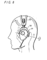
- FIG. 8 shows an example of a conventional headphone.
- a housing 21 having a built-in speaker unit is pivotally supported on an exterior type hanger 23 provided in a headband 22.
- the headband 22 is attached to the top of a head portion and the housing 21 can be swung and adjusted in a driving direction by setting a pivot O in the longitudinal direction as the center of swinging.
- An operation for attaching the headphone has a problem in that attachment is hard to perform because fingers touch part of the hanger 23 when the housing 21 is held.
- the housing 21 supported swingably is unsteady and is attached with difficulty without pressing down the housing 21 while holding the hanger 23.
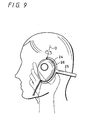
- FIG. 9 shows an example of another headphone of a conventional type.
- the headphone also has such a structure that a housing 24 including a speaker unit is supported pivotally by an exterior type hanger 26 provided in a headband 25.
- the headband 22 is attached to a rear head portion and the housing 24 can be swung and adjusted in a twist direction by setting a pivot O in the vertical direction as the center of swinging.
- the headphone has a problem that if the headband 25 is to be spread in order to attach.the headphone to the head portion by holding the housing 24 and the hanger 26, the housing 24 is turned from a pivot portion so that attachment property is very deteriorated.
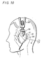
- FIG. 10 shows a headphone of a conventional type in which a hanger 27 is stored in a housing 28 in place of the above-mentioned exterior type hanger.
- a headphone having a hanger of a storage type has such a structure that an arm 30 of a headband 29 coupled to the hanger 27 is drawn from the housing 28.
- the headband 29 is attached to the top of the head portion, and the housing 28 is provided with an opening 31 such that the housing 28 can be swung in the driving direction by setting the pivot O in the longitudinal direction as the center of swinging.
- the opening 31 is formed on the housing 28, there is a problem that foreign substances, dust and the like enter the housing 28 or fingers are caught between the opening 31 and the arm 30 during the driving adjustment of the housing 28.
- the present invention has been made to eliminate the above-mentioned problems and has an object to obtain a headphone capable of preventing foreign substances, dust and the like from entering a housing and of enhancing acoustic characteristics.
- the present invention provides a headphone in which an opening formed in a coupling portion between a housing and a headband is concealed by shielding means.
- the opening of the housing is always concealed by the shielding means. Therefore, foreign substances, dust and the like do not enter the housing.
- the shielding means shields the opening by means of a shielding plate extended from the hanger of the headband, the opening is always blocked by the shielding plate even in case the housing is swung in the driving direction or the twist direction. Consequently, it is possible to prevent the foreign substances, the dust and the like from entering the housing.
- the inside of the housing is divided by a partition wall and a speaker unit has a sealing structure. Consequently, the acoustic characteristics of a speaker can be enhanced.
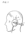
- FIG. 1 is a view showing the appearance of a state in which the headphone is attached
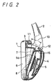
- FIG. 2 is a sectional view taken along the line A-A of FIG. 1
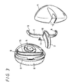
- FIG. 3 is a perspective view showing the main part of the headphone which is divided.
- the headband 2 has an arch-shaped hanger 7 provided integrally with an end, and convex shafts 8 and 8 provided in both tip portions of the hanger 7 are pivotally supported on shaft holes 9 and 9 (only one of the shaft holes 9 is shown in FIG. 3) of the housing body 3 so that the housing body 3 is held.
- the cover 4 is assembled into the housing body 3 having the headband 2 fixed thereto in order to cover the speaker unit 5 on the rear face side of the speaker unit 5 and is coupled with a screw which is not shown.
- the hanger 7 of the headband 2 is also stored in the cover 4.
- the headband 2 is attached to the rear head portion and the housing 2 can be adjusted in the twist direction by using a pivot O as the fulcrum of swinging with respect to the headband 2 as shown in FIG. 1.
- the cover 4 should be provided with an opening 10 for guiding the headband 2.
- the opening 10 is blocked by a shielding member formed on the headband 2.
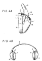
- the shielding plate 11 is integrally extended from the hanger 7 and a portion 12 integrally protruded from the headband 2 is formed on the side opposite to the shielding plate 11.
- the opening 10 of the housing 1 is blocked by the shielding plate 11 as shown in FIG. 4A.
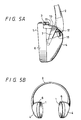
- the opening 10 of the housing 1 is blocked by the protruded portion 12 of the headband 2 as shown in FIG. 5A.
- the headphone is attached in the state shown in FIG. 4B or FIG. 5B depending on the size of a user's head portion.
- the opening 10 of the housing 1 can be always blocked by the shielding plate 11 and the protruded portion 12 also in any working condition of the headphone. Therefore, it is possible to prevent foreign substances, dust and the like from entering the housing 1, for example, and to avoid such a danger that fingers might be caught by mistake between the opening 10 and the headband 2 during the attachment of the headphone. Furthermore, it is possible to enhance the design of appearance of the headphone and to increase the value of goods.
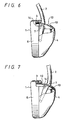
- a shielding sheet 13 for expanding or contracting like bellows which is formed of a rubber material, a soft plastic material, a cloth or the like may be attached between the hanger 7 and the cover 4 on the inside of the opening 10 and a shielding sheet 14 for expanding or contracting like bellows may be similarly attached between the hanger 7 and the housing body 3 on the inside of the opening 10 as shown in FIGS. 6 and 7.
- the shielding sheet 13 can expand to block the opening 10, while the shielding sheet 14 provided on the opposite side contracts.
- the shielding sheet 14 can expand to block the opening 10, while the shielding sheet 13 provided on the opposite side contracts. Consequently, it is possible to prevent the foreign substances, dust and the like from entering the housing 1. Furthermore, in the case in which the bellows-shaped shielding sheet is used, a manufacturing cost can be reduced.
- the housing 1 of the headphone according to the present invention has a sealing structure on the rear face side of the speaker unit 5. Consequently, the acoustic characteristics of the speaker can be enhanced.
- a rib-shaped partition wall 15 is formed to surround the speaker unit 5 on the rear face side of the housing body 3 as shown in FIGS. 2 and 3. More specifically, when the cover 4 is closed on the housing body 3, the speaker unit 5 side can have a sealing room structure from the opening 10 side by using the partition wall 15 as a dividing wall. Consequently, the acoustic characteristics of the speaker can be enhanced with a simple structure.
- the headband 2 can be hung on the rear head portion and the housing 1 can be adjusted in the twist direction. It is also possible to apply a headphone having such a structure that the headband 2 can be hung on the top of the head portion and the housing 1 can be adjusted in the driving direction.
- the opening formed in the coupling portion of the housing having the speaker unit and the storage type hanger and serving to swing and the headband is concealed by the shielding means. Therefore, it is possible to prevent foreign substances, dust and the like from entering the housing and to avoid such a danger that fingers might be caught by mistake between the opening and the headband during the attachment of the headphone. Furthermore, it is possible to enhance the design of appearance of the headphone and to increase the value of goods.
- the opening is shielded by the shielding member extended from the hanger as the shielding means. Consequently, it is possible to effectively block the opening by utilizing the member formed integrally with the hanger.
- the opening is shielded by the bellows-shaped shielding sheet provided in the headphone housing as the shielding means. Consequently, the shielding means can be manufactured inexpensively.
- the partition wall is provided in the headphone housing and the rear face side of the speaker unit has a sealing structure. Consequently, the acoustic characteristics of the speaker can be enhanced with a simple structure.
Landscapes
- Engineering & Computer Science (AREA)
- Physics & Mathematics (AREA)
- Acoustics & Sound (AREA)
- Signal Processing (AREA)
- Manufacturing & Machinery (AREA)
- Headphones And Earphones (AREA)
Abstract
an opening generated between the housing and the headband being blocked by a shielding plate formed on one side of the hanger and a protruded portion formed on the side opposite to the shielding plate.
Description
Claims (5)
- A headphone in which a hanger of a headband in a headphone housing having a speaker unit is of a storage type and is pivotally supported and coupled and the headphone housing can be swung in a driving direction or a twist direction with respect to the headband , wherein
a coupling portion is covered and concealed by part of the housing. - A headphone according to claim 1, wherein
an opening generated in a coupling portion between the headphone housing and the headband is blocked by shielding means. - The headphone according to claim 2, wherein
the shielding means shields the opening by means of a shielding member protruded from the hanger. - The headphone according to claim 2, wherein
the shielding means shields the opening by means of a bellows-shaped shielding sheet provided in the headphone housing. - The headphone according to any one of claims 1 to 4, wherein
a partition wall is provided in the headphone housing and a rear face side of the speaker unit has a sealing structure.
Applications Claiming Priority (2)
| Application Number | Priority Date | Filing Date | Title |
|---|---|---|---|
| JP19919899A JP4062824B2 (en) | 1999-07-13 | 1999-07-13 | Headphone |
| JP19919899 | 1999-07-13 |
Publications (3)
| Publication Number | Publication Date |
|---|---|
| EP1069802A2 true EP1069802A2 (en) | 2001-01-17 |
| EP1069802A3 EP1069802A3 (en) | 2003-05-21 |
| EP1069802B1 EP1069802B1 (en) | 2004-09-15 |
Family
ID=16403782
Family Applications (1)
| Application Number | Title | Priority Date | Filing Date |
|---|---|---|---|
| EP00305970A Expired - Lifetime EP1069802B1 (en) | 1999-07-13 | 2000-07-13 | Headphone |
Country Status (9)
| Country | Link |
|---|---|
| US (1) | US6542615B1 (en) |
| EP (1) | EP1069802B1 (en) |
| JP (1) | JP4062824B2 (en) |
| KR (1) | KR100655499B1 (en) |
| CN (1) | CN1283065A (en) |
| DE (1) | DE60013709T2 (en) |
| MY (1) | MY123408A (en) |
| SG (1) | SG90148A1 (en) |
| TW (1) | TW471234B (en) |
Cited By (3)
| Publication number | Priority date | Publication date | Assignee | Title |
|---|---|---|---|---|
| DE102005063075A1 (en) * | 2005-12-29 | 2007-07-05 | Sennheiser Electronic Gmbh & Co. Kg | Headset e.g. nape holder headset, has nape holder, and two ear pads that are arranged at ends of nape holder that is pre-tensioned, where ear pads are designed as convex such that ear pads fit in form of outer ear |
| CN1333619C (en) * | 2003-01-31 | 2007-08-22 | Akg声学有限公司 | Headphone |
| CN1333620C (en) * | 2003-01-31 | 2007-08-22 | Akg声学有限公司 | Headphone |
Families Citing this family (23)
| Publication number | Priority date | Publication date | Assignee | Title |
|---|---|---|---|---|
| ES2382114T3 (en) * | 2006-01-04 | 2012-06-05 | Coby Electronics Corporation | Helmets with detachable headband |
| KR100825959B1 (en) | 2007-10-02 | 2008-05-02 | (주)케이에이브이 | Ceiling Mount Speaker |
| US7549178B2 (en) * | 2007-10-12 | 2009-06-23 | Kimberly-Clark Worldwide, Inc. | Patch for securing a surgical gown tie |
| CA2740296C (en) * | 2010-01-06 | 2018-05-01 | Skullcandy, Inc. | Dj mixing headphones |
| CN102232888B (en) * | 2010-04-21 | 2013-08-21 | 声腾企业有限公司 | Earmuff structure |
| GB2500159B (en) | 2011-01-03 | 2018-08-22 | Apple Inc | Audio listening system |
| CN102231866B (en) * | 2011-04-22 | 2013-12-18 | 浙江魔杰电子股份有限公司 | Headset with earflaps capable of rotating and extending relative to head band |
| CN102291639A (en) * | 2011-06-23 | 2011-12-21 | 邦拓国际有限公司 | Multimedia earplug accessory and multimedia earplug holder adopting the accessory |
| US8861770B2 (en) * | 2013-01-23 | 2014-10-14 | Koss Corporation | Headband for personal speakers |
| US8737668B1 (en) * | 2013-01-23 | 2014-05-27 | Koss Corporation | Headband for personal speakers |
| CN104254037B (en) * | 2014-09-30 | 2017-08-11 | 广东欧珀移动通信有限公司 | Auricular concha rotating shaft mechanism and its headphone |
| US9522086B2 (en) | 2015-01-06 | 2016-12-20 | Honeywell International Inc. | Headband folding mechanism allowing two axis folding directions |
| US10667029B2 (en) * | 2015-07-16 | 2020-05-26 | Voyetra Turtle Beach, Inc. | Headset with internal gimbal |
| CN105959840B (en) * | 2015-11-03 | 2020-08-04 | 深圳升韵声学有限公司 | An elastic joint headphone |
| US10085085B2 (en) * | 2017-02-01 | 2018-09-25 | Bose Corporation | Headphone |
| US10129632B2 (en) * | 2017-02-01 | 2018-11-13 | Bose Corporation | Headphone |
| US11208912B2 (en) | 2018-12-13 | 2021-12-28 | General Electric Company | Turbine engine with floating shrouds |
| JP7266872B2 (en) * | 2019-09-13 | 2023-05-01 | 株式会社オーディオテクニカ | headphones and earmuffs |
| US11729553B2 (en) * | 2020-05-29 | 2023-08-15 | Sony Interactive Entertainment Inc. | Headset mechanism for comfort coupling ear cups to head |
| KR102860388B1 (en) | 2021-02-08 | 2025-09-16 | 삼성전자주식회사 | Headset with Variable Band Type |
| US20240080607A1 (en) * | 2022-09-07 | 2024-03-07 | Sony Interactive Entertainment LLC | Headset with pivoting ear cups |
| US12382206B2 (en) | 2022-09-07 | 2025-08-05 | Sony Interactive Entertainment LLC | Headset with reciprocating microphone support |
| US20240171897A1 (en) * | 2022-11-22 | 2024-05-23 | Justin Lee | Adjustable and Retractable Headset For Enhanced Hearing Experience |
Family Cites Families (17)
| Publication number | Priority date | Publication date | Assignee | Title |
|---|---|---|---|---|
| US4027113A (en) * | 1974-09-12 | 1977-05-31 | Nippon Gakki Seizo Kabushiki Kaisha | Headphone |
| AT348050B (en) * | 1976-08-30 | 1979-01-25 | Akg Akustische Kino Geraete | HEADPHONE WITH MICROPHONE |
| US4065645B1 (en) * | 1976-10-26 | 1993-05-18 | Audiotronics Corporation | Headset |
| US4542803A (en) * | 1984-05-31 | 1985-09-24 | Houng Huang C | Detachable inflight headset for civil aircraft |
| US4588868A (en) * | 1984-07-12 | 1986-05-13 | Avicom International, Inc. | Headset |
| US4689822A (en) * | 1986-01-29 | 1987-08-25 | Houng Huang Chiang | Headset |
| US4949806A (en) * | 1988-12-20 | 1990-08-21 | Stanton Magnetics, Inc. | Headset for underwater use |
| US5109424A (en) * | 1989-01-19 | 1992-04-28 | Koss Corporation | Stereo headphones with plug, receptacle and securing plates |
| US4965836A (en) * | 1989-01-19 | 1990-10-23 | Koss Corporation | Stereo headphone |
| JP2870791B2 (en) * | 1989-03-20 | 1999-03-17 | ソニー株式会社 | Wireless headphones |
| US5035005A (en) * | 1990-07-27 | 1991-07-30 | Hung Huang C | Inflight headset for civil aircraft |
| US5117464A (en) * | 1991-03-08 | 1992-05-26 | Jones Edward I | Adjustable clip-on headphones |
| JP3111757B2 (en) * | 1993-06-14 | 2000-11-27 | ソニー株式会社 | Headphones |
| JP3318442B2 (en) * | 1994-07-20 | 2002-08-26 | アイワ株式会社 | headphone |
| US5793878A (en) * | 1997-06-05 | 1998-08-11 | Chang; Ching-Wen | Headset microphone having a location apparatus |
| US5887286A (en) * | 1998-01-22 | 1999-03-30 | Waldron; Carolyn A. | Ear protector |
| US5970105A (en) * | 1998-05-11 | 1999-10-19 | Cleveland Medical Devices Inc. | Apparatus and method for efficient wireless communications in the presence of frequency error |
-
1999
- 1999-07-13 JP JP19919899A patent/JP4062824B2/en not_active Expired - Fee Related
-
2000
- 2000-07-11 SG SG200003876A patent/SG90148A1/en unknown
- 2000-07-11 KR KR1020000039635A patent/KR100655499B1/en not_active Expired - Fee Related
- 2000-07-11 TW TW089113782A patent/TW471234B/en not_active IP Right Cessation
- 2000-07-13 MY MYPI20003204 patent/MY123408A/en unknown
- 2000-07-13 DE DE60013709T patent/DE60013709T2/en not_active Expired - Lifetime
- 2000-07-13 US US09/615,204 patent/US6542615B1/en not_active Expired - Lifetime
- 2000-07-13 CN CN00126284A patent/CN1283065A/en active Pending
- 2000-07-13 EP EP00305970A patent/EP1069802B1/en not_active Expired - Lifetime
Cited By (3)
| Publication number | Priority date | Publication date | Assignee | Title |
|---|---|---|---|---|
| CN1333619C (en) * | 2003-01-31 | 2007-08-22 | Akg声学有限公司 | Headphone |
| CN1333620C (en) * | 2003-01-31 | 2007-08-22 | Akg声学有限公司 | Headphone |
| DE102005063075A1 (en) * | 2005-12-29 | 2007-07-05 | Sennheiser Electronic Gmbh & Co. Kg | Headset e.g. nape holder headset, has nape holder, and two ear pads that are arranged at ends of nape holder that is pre-tensioned, where ear pads are designed as convex such that ear pads fit in form of outer ear |
Also Published As
| Publication number | Publication date |
|---|---|
| SG90148A1 (en) | 2002-07-23 |
| JP2001028792A (en) | 2001-01-30 |
| DE60013709D1 (en) | 2004-10-21 |
| TW471234B (en) | 2002-01-01 |
| DE60013709T2 (en) | 2005-09-29 |
| EP1069802A3 (en) | 2003-05-21 |
| US6542615B1 (en) | 2003-04-01 |
| EP1069802B1 (en) | 2004-09-15 |
| CN1283065A (en) | 2001-02-07 |
| JP4062824B2 (en) | 2008-03-19 |
| KR20010015284A (en) | 2001-02-26 |
| MY123408A (en) | 2006-05-31 |
| KR100655499B1 (en) | 2006-12-08 |
Similar Documents
| Publication | Publication Date | Title |
|---|---|---|
| EP1069802B1 (en) | Headphone | |
| JP5432694B2 (en) | Battery storage mechanism for noise canceling headphones | |
| KR100767463B1 (en) | Headphone device | |
| US4775083A (en) | Portable radio carrying case | |
| JP2001045584A (en) | Microphone | |
| CN109076277A (en) | Headset assembly with the wing tip for being fixed to user | |
| CA2286634A1 (en) | Headset assembly | |
| CA1088872A (en) | Ear defenders | |
| JPH07298383A (en) | Headphone device | |
| US20010043711A1 (en) | Headphone | |
| JP3154136B2 (en) | Headphone equipment | |
| JP3318442B2 (en) | headphone | |
| JP3873161B2 (en) | Portable terminal | |
| JPH08294191A (en) | Headphone device | |
| JP2001211491A (en) | Earphone microphone | |
| JPH04319841A (en) | Ear set | |
| JP4147998B2 (en) | Housing with boss that eliminates sharp edges | |
| EP1185137A2 (en) | Headphone device | |
| CN210379569U (en) | Positioning mechanism for splash box and splash box with positioning mechanism | |
| CN209375885U (en) | Adjustable earphone | |
| JP2546600Y2 (en) | Inner phone | |
| JP2577201Y2 (en) | headphone | |
| JP2001065907A (en) | Air conditioner indoor unit | |
| WO2025223013A1 (en) | Headband and headphone | |
| KR960030876A (en) | Vacuum cleaner dust cover mounting structure |
Legal Events
| Date | Code | Title | Description |
|---|---|---|---|
| PUAI | Public reference made under article 153(3) epc to a published international application that has entered the european phase |
Free format text: ORIGINAL CODE: 0009012 |
|
| AK | Designated contracting states |
Kind code of ref document: A2 Designated state(s): AT BE CH CY DE DK ES FI FR GB GR IE IT LI LU MC NL PT SE |
|
| AX | Request for extension of the european patent |
Free format text: AL;LT;LV;MK;RO;SI |
|
| PUAL | Search report despatched |
Free format text: ORIGINAL CODE: 0009013 |
|
| AK | Designated contracting states |
Designated state(s): AT BE CH CY DE DK ES FI FR GB GR IE IT LI LU MC NL PT SE |
|
| AX | Request for extension of the european patent |
Extension state: AL LT LV MK RO SI |
|
| RIC1 | Information provided on ipc code assigned before grant |
Ipc: 7H 04R 5/033 B Ipc: 7H 04R 1/10 A |
|
| 17P | Request for examination filed |
Effective date: 20031024 |
|
| AKX | Designation fees paid |
Designated state(s): DE FR GB |
|
| GRAP | Despatch of communication of intention to grant a patent |
Free format text: ORIGINAL CODE: EPIDOSNIGR1 |
|
| GRAS | Grant fee paid |
Free format text: ORIGINAL CODE: EPIDOSNIGR3 |
|
| GRAA | (expected) grant |
Free format text: ORIGINAL CODE: 0009210 |
|
| AK | Designated contracting states |
Kind code of ref document: B1 Designated state(s): DE FR GB |
|
| REG | Reference to a national code |
Ref country code: GB Ref legal event code: FG4D |
|
| REG | Reference to a national code |
Ref country code: IE Ref legal event code: FG4D |
|
| REF | Corresponds to: |
Ref document number: 60013709 Country of ref document: DE Date of ref document: 20041021 Kind code of ref document: P |
|
| PLBE | No opposition filed within time limit |
Free format text: ORIGINAL CODE: 0009261 |
|
| STAA | Information on the status of an ep patent application or granted ep patent |
Free format text: STATUS: NO OPPOSITION FILED WITHIN TIME LIMIT |
|
| ET | Fr: translation filed | ||
| 26N | No opposition filed |
Effective date: 20050616 |
|
| PGFP | Annual fee paid to national office [announced via postgrant information from national office to epo] |
Ref country code: FR Payment date: 20110729 Year of fee payment: 12 |
|
| PGFP | Annual fee paid to national office [announced via postgrant information from national office to epo] |
Ref country code: DE Payment date: 20110722 Year of fee payment: 12 Ref country code: GB Payment date: 20110721 Year of fee payment: 12 |
|
| GBPC | Gb: european patent ceased through non-payment of renewal fee |
Effective date: 20120713 |
|
| REG | Reference to a national code |
Ref country code: FR Ref legal event code: ST Effective date: 20130329 |
|
| PG25 | Lapsed in a contracting state [announced via postgrant information from national office to epo] |
Ref country code: DE Free format text: LAPSE BECAUSE OF NON-PAYMENT OF DUE FEES Effective date: 20130201 Ref country code: GB Free format text: LAPSE BECAUSE OF NON-PAYMENT OF DUE FEES Effective date: 20120713 Ref country code: FR Free format text: LAPSE BECAUSE OF NON-PAYMENT OF DUE FEES Effective date: 20120731 |
|
| REG | Reference to a national code |
Ref country code: DE Ref legal event code: R119 Ref document number: 60013709 Country of ref document: DE Effective date: 20130201 |