EP1069700A2 - Echo cancellation for an ADSL modem - Google Patents
Echo cancellation for an ADSL modem Download PDFInfo
- Publication number
- EP1069700A2 EP1069700A2 EP00305711A EP00305711A EP1069700A2 EP 1069700 A2 EP1069700 A2 EP 1069700A2 EP 00305711 A EP00305711 A EP 00305711A EP 00305711 A EP00305711 A EP 00305711A EP 1069700 A2 EP1069700 A2 EP 1069700A2
- Authority
- EP
- European Patent Office
- Prior art keywords
- signal
- echo
- analog
- training
- transfer function
- Prior art date
- Legal status (The legal status is an assumption and is not a legal conclusion. Google has not performed a legal analysis and makes no representation as to the accuracy of the status listed.)
- Granted
Links
Images


Classifications
-
- H—ELECTRICITY
- H04—ELECTRIC COMMUNICATION TECHNIQUE
- H04B—TRANSMISSION
- H04B3/00—Line transmission systems
- H04B3/02—Details
- H04B3/20—Reducing echo effects or singing; Opening or closing transmitting path; Conditioning for transmission in one direction or the other
- H04B3/23—Reducing echo effects or singing; Opening or closing transmitting path; Conditioning for transmission in one direction or the other using a replica of transmitted signal in the time domain, e.g. echo cancellers
Definitions
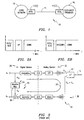
- the ADSL modem 12 divides the available bandwidth of the twisted pair telephone line in one of two ways.
- frequency division multiplexing FDM
- FDM frequency division multiplexing
- the bands for uplink and downlink data communication are assigned to partially overlay one another, and local echo cancellation is used at each end of the twisted pair line 14 to separate the two bands from each other and recover the transmitted information.
- the ADSL modem 12 splits off the four kilohertz voice band at the DC end of the available bandwidth to support conventional communications services.
- the magnitude of the receive component Vrx of the composite signal Vrx+Ve may be very small relative to the magnitude of the echo portion Ve.
- the modem 12 components in the receive channel 30, especially those components located within the analog domain 32 such as the receive amplifier, filters and analog-to-digital converter, must be capable of handling signals with a relatively large dynamic range (in the order of 80-90 dB). While it is possible to design and build such a device, its design and implementation present quite complicated and expensive propositions that detract from the advantages of ADSL technology.
- Still another limitation of a fully digital echo canceler is the substantial computational complexity of the adaptive filter 24 (comparable of that of an entire modem), which arises due to the high complexity of the echo path 33 transfer function that incorporates transmit, echo and receive chains. There is accordingly a need for a less complicated and expensive echo cancellation functionality for use within ADSL modems.
- the echo cancellation functionality is implemented within the modem to provide two operational modes.
- a first (training) mode of operation the echo cancellation functionality configures the transmit channel, echo channel and receive channel of the modem to either by-pass certain modem components having transfer functions that would otherwise introduce amplitude and phase distortions in an error signal (comprising the echo component minus the echo cancellation signal), or to define some transfer functions in the modem, in order to tune the transfer function of the adaptive filter to substantially match the echo transfer function.
- the echo cancellation functionality configures the modem into a second (operating) mode of operation to support information transfer to and from the modem over the twisted pair.
- the adaptive filter may comprise any tunable finite or infinite impulse response filter including known least mean square, Kalman and recursive mean square types.
- the modem comprises a least mean square type finite impulse response adaptive filter that may also contain a predistortion function in accordance with the present invention.
- the adaptive filter accordingly includes a first n-tap delay line and a recursive tap weight update section in accordance with conventional filter design.
- the adaptive filter further includes a second n-tap delay line with a filter block whose transfer function substantially matches a combined transfer function for an adaptation loop of the modem comprising the echo channel and the receive channel. The outputs of the second n-tap delay line then generate a predistortion vector for input to the recursive tap weight update section of the adaptive filter.
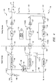
- FIGURE 4 a block diagram for a mixed analog/digital domain adaptive echo canceler 110 of the present invention for use within the ADSL modem 12 of FIGURE 1.
- the echo canceler 110 includes a plurality of analog and digital switches 112 operable to switch the modem 12 (and more particularly its echo cancellation functionality) between an operating mode (selected generally speaking when the switches 112 are placed in the "1" position) and a training mode (selected generally speaking when the switches 112 are placed in the "2" position). More specifically, a switch controller 113 selects switch 112 position (either "1" or "2") of certain ones of the switches and thus places the echo canceler 110 in the proper mode of operation.
- the nature of the interface 126 and the line impedance matching conditions result in E(s) having a modulus that is essentially of the high pass type with a magnitude typically oscillating around 0.5 in the frequency band of interest (but may, under various termination conditions, have a normalized magnitude with a value of anywhere between zero and one). Due to the high losses experienced with transmission of signals over the twisted pair line 14, the magnitude of the receive component Vrx of the composite signal Vrx+Ve may be very small relative to the magnitude of the echo portion Ve. transmit channel 124 onto the twisted pair line 14 for communication.
- the cancellation of the Ve echo component occurs in the analog domain by having a subtractor 128 subtract an echo cancellation signal Ve' from the composite signal Vrx+Ve.
- a receive signal Vrx' is generated that is substantially equal to the receive signal Vrx received over the line 14 at the interface 126.
- the echo cancellation signal Ve' is generated by processing the digital transmit signal received on line 114 (after passing through switch 112(1)) through a digital domain adaptive finite impulse response (FIR) filter 130 having a transfer function H FIR (z) which adaptively approximates the echo transfer function E(s).
- FIR digital domain adaptive finite impulse response
- the transfer functions H and E for the corresponding components in the canceler 110 are defined in terms of the complex frequency variable j ⁇ , and all signals in the signal flow diagram may be represented by their Fourier transforms. More specifically, the transfer function H I (j ⁇ ) defines the transfer characteristics of the interpolators 116 and 116', the transfer function H D (j ⁇ ) defines the transfer characteristics of the decimator 140, the transfer function H TX (j ⁇ ) defines the transfer characteristics of the transmit filter 120, the transfer function H E (j ⁇ ) defines the transfer characteristics of the echo filter 120', and the transfer function H RX (j ⁇ ) defines the transfer characteristics of the receive filters 136.
- the transfer functions H FIR (j ⁇ ) and E(j ⁇ ) are as discussed above relating to the transfer function of the adaptive filter 130 and the echo transfer function at the interface 126.
- the transform TR corresponds to the training signal output of the signal generator 148.
- the transform YD corresponds to the receive channel output from the interface 126.
- the resulting analog echo (training) signal then by-passes any processing in the low pass filter 120', passes through switch 112(5), and is amplified 122' to generate the echo (training) cancellation signal Ve' for application to the inverting input of the summer 128.
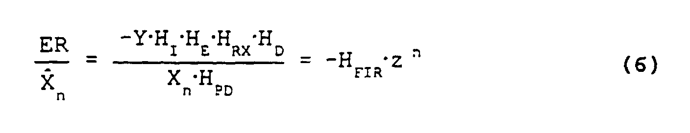
- the echo (training) cancellation signal Ve' is then subtracted from the echo (training) signal Ve to generate an error (training) signal ER.
- the actual echo channel of the modem is not required in this mode (as illustrated), so it must be disconnected by disabling, for example, the converter 118'.
- the adaptation of the filter 130 may be performed either in real time, during acquisition of the training signal, or off-line after the acquisition is completed, in either case using the above-mentioned LMS algorithm.
- the adaptive filter transfer function converges essentially to the product of the echo and low pass filter transfer functions.
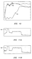
- the adaptive filter 130 finite impulse response length was chosen to be twenty-one tap.
- the adaptation results calculated in the frequency domain after approximately two-thousand steps of training are illustrated in FIGURE 6. What this illustrates is that for a significant portion of the band of interest (for example, up to approximately the end of the overlap band in FIGURE 2B), the adaptive filter response 150 substantially matches the echo response 152 producing echo leakage 154 levels in the range of up to minus fifty dB.
- a corresponding simulation performed concerning operation of the echo cancellation system of the first type confirms the effectiveness of the echo cancellation operation.
- FIGURES 7A and 7B Transmit and receive signals corresponding to the non-overlapped spectral usage operation were simulated with the results illustrated in FIGURES 7A and 7B in the form of composite receive and echo canceler output signal PSD characteristics. What this illustrates is that the excessive dynamic range in the analog signal (see, FIGURE 7A, generally at 156) is dramatically reduced at the echo canceler output (see, FIGURE 7B, generally at 158) in the range of up to a fifty dB reduction.
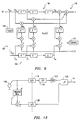
- the operation of the adaptive filter is predistorted to account for the amplitude and phase distortions introduced in the error signal ER by the transfer functions H for the components (interpolator 116', filter 120', filters 136 and decimator 140) of the echo channel 132 and receive channel 144.
- the goal of the training in this configuration is to define the predistortion transfer function of the filter 186 in FIGURE 9. This may be achieved by configuring the modem as follows: switch 112(1) is placed in the "2" position, and switches 112(4), 112(5), 112(6) and 112(7) are placed in the "1" position.
- Adaptive filter feedback is connected by a way indicated at 146 in FIGURE 4.
- the transfer function H PD is realized in the digital domain. However, it is recognized that any given analog transfer function component appearing in the adaptation loop transfer function of H I ⁇ H E ⁇ H RX ⁇ H D may only be approximately reproduced in the digital domain. This presents a theoretical limitation on the design realization for the filter. Still further, it is recognized that setting the proper value for the adaptation constant ⁇ is required to ensure convergence.
- the training mode for the echo canceler of the second type may be simplified as only one switch, 112(1), is needed to toggle between the train and operate modes of the modem.
- the modified LMS adaptive filter 130 finite impulse response length was chosen to be seventeen tap with an eight tap predistortion filter.
- the adaptation results calculated in the frequency domain after approximately two-thousand steps of training are illustrated in FIGURE 10. What this illustrates is that for a significant portion of the band of interest (for example, up to approximately the end of the overlap band in FIGURE 2B), the modified LMS adaptive filter response 160 substantially matches the echo response 162 producing echo leakage 164 levels in the range of up to minus forty dB.
- a corresponding simulation performed concerning operation of the echo cancellation system of the send type confirms the effectiveness of the echo cancellation operation.
- the modified second type LMS adaptive filter 130 for the echo canceler 110 of FIGURE 4 allows for the possibility of continuous mode operation (as opposed to training mode operation) with respect to the echo cancellation process.
- a benefit of such an operation is that adaptation of the filter 130 would continue within the echo canceler 110 following (or in the absence of) completion of training mode. Use of this mode could also imply the use of the actual transmit signal (instead of a training signal) for use in the modified LMS adaptive filter 130 as the training sequence.
- the modified LMS adaptive filter 130 response When configured for use within an ADSL modem 12 having automatic gain control and a transmit signal whose spectral and amplitude characteristics may vary considerably during operation (such as with the digital multi-tone modulation based G.Lite ADSL implementation), the modified LMS adaptive filter 130 response must continuously change in time.
Landscapes
- Engineering & Computer Science (AREA)
- Computer Networks & Wireless Communication (AREA)
- Signal Processing (AREA)
- Cable Transmission Systems, Equalization Of Radio And Reduction Of Echo (AREA)
- Telephonic Communication Services (AREA)
Abstract
Description


Claims (22)
- A bi-directional communications device including both an analog processing domain and a digital processing domain, comprising:a transmit channel spanning the digital and analog processing domains for processing a transmit signal;a receive channel spanning the analog and digital processing domains for processing a receive signal;a line interface in the analog processing domain for transmitting the transmit signal over a communications line, and for receiving the receive signal as corrupted by an unwanted echo component of the transmit signal from the communications line; andan echo channel spanning the digital and analog processing domains and including:a tap in the digital processing domain for tapping the transmit signal from the transmit channel;an adaptive filter in the digital processing domain for processing the tapped transmit signal to generate an echo cancellation signal, the adaptive filter having a transfer function substantially matching an echo transfer function which defines a relationship at the interface between the transmit signal and the unwanted echo component; anda converter for converting the echo cancellation signal to an analog echo cancellation signal; andwherein the receive channel further includes a summer in the analog processing domain for subtracting the analog echo cancellation signal from the echo component corrupted receive signal and outputting a corrected receive signal for further processing in the receive channel.
- The communications device of claim 1 wherein the communications line comprises a twisted pair telephone line.
- The communications device of claim 2 wherein the device comprises a modem.
- The communications device of claim 3 wherein the modem comprises an Asymmetric Digital Subscriber Line (ADSL) modem.
- The communications device of claim 1 wherein the transmit channel comprises:a first interpolator;a first digital-to-analog converter having an input connected to an output of the first interpolator;a first low pass filter having an input connected to an output of the first digital-to-analog converter; anda first amplifier driver having an input connected to an output of the first low pass filter and an output connected to the line interface.
- The communications device of claim 5 wherein the echo channel comprises:the adaptive filter;a second interpolator having an input connected to an output of the adaptive filter;a second digital-to-analog converter having an input connected to an output of the second interpolator;a second low pass filter having an input connected to an output of the second digital-to-analog converter; anda second amplifier having an input connected to an output of the second low pass filter and an output connected to the summer.
- The communications device of claim 6 wherein:the first and second interpolators have substantially matching transfer functions; andthe first and second low pass filters have substantially matching transfer functions.
- The communications device of claim 6 wherein the receive channel comprises:a line receiver having an input connected to an output of the summer;filter means having an input connected to an output of the line receiver;an analog-to-digital converter having an input connected to an output of the filter means; anda decimator having an input connected to an output of the analog to digital converter.
- The communications device of claim 8 further comprising:a first switch moveable between an operating position connecting the transmit channel to receive the transmit signal and a training position connecting the transmit channel to receive a training signal;a second switch moveable between an operating position wherein the first interpolator processes the transmit signal and a training position wherein the training signal is by-passed around the first interpolator;a third switch moveable between an operating position wherein the first low pass filter processes the transmit signal and a training position wherein the training signal is by-passed around the first low pass filter.
- The communications device of claim 8 further comprising:a fourth switch moveable between an operating position wherein the second interpolator processes the echo cancellation signal output from the adaptive filter and a training position wherein the echo cancellation signal is by-passed around the second interpolator;a fifth switch moveable between an operating position wherein the second low pass filter processes the echo cancellation signal and a training position wherein the echo cancellation signal is by-passed around the second low pass filter;a sixth switch moveable between an operating position wherein the corrected receive signal is processed through the line receiver and filter means and a training position wherein the corrected receive signal comprising an error correction signal is by-passed around the line receiver and filter means; anda seventh switch moveable between an operating wherein the corrected receive signal is processed by the decimator and a training position wherein the error correction signal is routed to the adaptive filter.
- The communications device of claim 10 further including a switch controller operating responsive to the initiation of communication through the communications device for moving certain ones of the switches into the training position for a short period of time necessary to adaptively configure the transfer function of the adaptive filter to substantially match the echo transfer function.
- The communications device of claim 1 wherein the adaptive filter comprises a least mean square finite impulse response filter.
- The communications device of claim 12 wherein the least mean square filter comprises:a first n-tap delay line;a recursive tap weight update section connected to the first n-tap delay line;a predistortion filter having a transfer function substantially matching a combined transfer function for the echo channel and the receive channel; anda second n-tap delay line having an input connected to an output of the filter and an output generating a predistortion vector for input to the recursive tap weight update section.
- An echo cancellation functionality, comprising: an adaptation loop, including:a receive channel for processing a received analog receive signal; andan echo channel, including:a digital adaptive filter for processing a digital transmit signal to generate a digital echo cancellation signal, the adaptive filter having a transfer function substantially matching an echo transfer function which defines a relationship between the transmit signal and an unwanted echo component corrupting the analog receive signal; anda converter for converting the digital echo cancellation signal to an analog echo cancellation signal; anda summer operable to subtract the analog echo cancellation signal from the echo component corrupted analog receive signal and output the receive signal for further processing in the receive channel.
- The echo cancellation functionality of claim 14 wherein adaptation loop has a combined transfer function and wherein the adaptive filter comprises:an adaptation functionality responsive to an error correction signal for adaptively configuring an overall transfer function of the adaptive filter to substantially match the echo transfer functionality; anda predistortion functionality for predistorting the overall transfer function of the adaptive filter to account for the combined transfer function of the adaptation loop.
- The echo cancellation functionality of claim 15 further including switch means operable to place the echo cancellation functionality in a training mode wherein adaptation loop processed signals by-pass certain components of the adaptation loop which contribute to the combined transfer function and wherein the receive channel generates the error correction signal for application to the adaptation functionality of the adaptive filter.
- The echo cancellation functionality of claim 16 further including a switch controller for placing certain switch means into the training mode for a short period of time necessary to adaptively configure the overall transfer function of the adaptive filter to substantially match the echo transfer function.
- The echo cancellation functionality of claim 15 wherein the predistortion functionality comprises:a predistortion filter having a transfer function substantially matching the combined transfer function for the adaptation loop; anda first n-tap delay line having an input connected to an output of the filter and an output generating a predistortion vector; and wherein the adaptation functionality comprises:a second n-tap delay line; anda recursive tap weight update section connected to the first n-tap delay line and responsive to the error correction signal and the predistortion vector to adaptively configure the overall transfer function to substantially match the echo transfer function.
- A method, comprising the steps of:processing a first signal in a transmit channel spanning a digital processing domain and an analog processing domain;transmitting the first signal over a communications line;receiving a second signal from the communications line, the second signal being corrupted by an unwanted echo component of the first signal;processing the receive signal in a receive channel spanning the analog and digital processing domains;tapping in the digital processing domain the first signal from the transmit channel;adaptively filtering in the digital processing domain the tapped first signal to generate an echo cancellation signal, the adaptive filter having a transfer function substantially matching an echo transfer function which defines a relationship between the first signal and the unwanted echo component;converting the echo cancellation signal to an analog echo cancellation signal; andsubtracting in the analog processing domain the analog echo cancellation signal from the echo component corrupted second signal and outputting a corrected second signal for further processing in the receive channel.
- The method of claim 19, further including the step of training the adaptive filter transfer function to substantially match the echo transfer function.
- The method of claim 20 wherein the step of training is performed at the beginning of each new communication.
- The method of claim 20 wherein the step of training comprises the steps of:applying a training signal to the transmit channel as the transmit signal;tapping in the digital processing domain the first training from the transmit channel;adaptively filtering in the digital processing domain the tapped training signal to generate an echo cancellation training signal;converting the echo cancellation training signal to an analog echo cancellation signal;subtracting in the analog processing domain the analog echo cancellation training signal from the echo component corrupted second signal and outputting a corrected training signal; andadjusting the adaptive filter transfer function in response to the corrected training signal to drive the echo cancellation training signal closer to substantially zero.
Applications Claiming Priority (2)
| Application Number | Priority Date | Filing Date | Title |
|---|---|---|---|
| US09/352,813 US6480532B1 (en) | 1999-07-13 | 1999-07-13 | Echo cancellation for an ADSL modem |
| US352813 | 1999-07-13 |
Publications (3)
| Publication Number | Publication Date |
|---|---|
| EP1069700A2 true EP1069700A2 (en) | 2001-01-17 |
| EP1069700A3 EP1069700A3 (en) | 2004-06-23 |
| EP1069700B1 EP1069700B1 (en) | 2008-08-13 |
Family
ID=23386607
Family Applications (1)
| Application Number | Title | Priority Date | Filing Date |
|---|---|---|---|
| EP00305711A Expired - Lifetime EP1069700B1 (en) | 1999-07-13 | 2000-07-06 | Echo cancellation for an ADSL modem |
Country Status (3)
| Country | Link |
|---|---|
| US (1) | US6480532B1 (en) |
| EP (1) | EP1069700B1 (en) |
| DE (1) | DE60039822D1 (en) |
Families Citing this family (37)
| Publication number | Priority date | Publication date | Assignee | Title |
|---|---|---|---|---|
| KR100330237B1 (en) * | 1999-07-19 | 2002-03-25 | 윤종용 | apparatus and method for estimating an echo path delay |
| US6985521B1 (en) * | 2000-01-07 | 2006-01-10 | Ikanos Communication, Inc | Method and apparatus for channel estimation for X-DSL communications |
| US7023812B1 (en) * | 2000-02-15 | 2006-04-04 | Siemens Communications, Inc. | System and method for improving modem transmission through private branch exchanges, central offices, and other systems |
| US6963603B1 (en) | 2000-06-06 | 2005-11-08 | Ikanos Communication, Inc. | Method and apparatus for pre-compensation of an XDSL modem |
| US6671374B1 (en) * | 2000-08-03 | 2003-12-30 | Globespanvirata, Inc. | Adaptive filter for echo cancellation, method for operating an adaptive filter for echo cancellation, an article of manufacture for determining tap weights and a length for an adaptive filter for echo cancellation and a computer implemented control system for determining tap weights and a length for an adaptive filter for echo cancellation |
| US6728368B1 (en) * | 2000-11-06 | 2004-04-27 | Centillium Communications, Inc. | Apparatus and method for a highly efficient low power driver for a central office ADSL system |
| US6785384B2 (en) * | 2000-12-04 | 2004-08-31 | Agere Systems Inc. | Two-step algorithm for training an echo cancellation filter |
| US6711216B2 (en) * | 2001-06-28 | 2004-03-23 | Intel Corporation | Method and apparatus for an ultra-wideband radio utilizing MEMS filtering |
| US20030112860A1 (en) * | 2001-12-18 | 2003-06-19 | Erdogan Alper Tunga | Method and system for shortening channel impulse response using time domain equalization filter |
| US6961373B2 (en) * | 2002-07-01 | 2005-11-01 | Solarflare Communications, Inc. | Method and apparatus for channel equalization |
| US7065167B2 (en) * | 2002-07-10 | 2006-06-20 | Solarflare Communications, Inc. | Method and apparatus for constellation shaping |
| US7133425B2 (en) * | 2002-07-10 | 2006-11-07 | Solarflare Communications, Inc. | Communication system |
| US7809021B2 (en) | 2002-07-10 | 2010-10-05 | Solarflare Communications, Inc. | Communication system and encoding method having low overhead |
| US7023963B1 (en) | 2002-09-18 | 2006-04-04 | Adtran, Inc. | DSL line card echo canceler-based mechanism for locating telecommunication line fault |
| US7164764B2 (en) * | 2002-11-07 | 2007-01-16 | Solarflare Communications, Inc. | Method and apparatus for precode crosstalk mitigation |
| US6912208B2 (en) * | 2002-11-07 | 2005-06-28 | Solarflare Communications, Inc. | Method and apparatus for equalization and crosstalk mitigation |
| US20040114676A1 (en) * | 2002-12-13 | 2004-06-17 | Texas Instruments Incorporated | Upstream signal optimizer with a transmitter employing the same and a method of optimizing an upstream signal |
| US7274732B2 (en) * | 2003-03-21 | 2007-09-25 | Texas Instruments Incorporated | Echo cancellation in communication systems with asymmetric data rates |
| US7126378B2 (en) * | 2003-12-17 | 2006-10-24 | Rambus, Inc. | High speed signaling system with adaptive transmit pre-emphasis |
| US7002897B2 (en) * | 2003-04-28 | 2006-02-21 | Solarflare Communications, Inc. | Multiple channel interference cancellation |
| JP2006524970A (en) * | 2003-04-28 | 2006-11-02 | ソーラーフレア・コミュニケーションズ・インコーポレイテッド | Eliminate interference in multiple channels |
| US8363535B2 (en) * | 2003-04-28 | 2013-01-29 | Marvell International Ltd. | Frequency domain echo and next cancellation |
| US20040213354A1 (en) * | 2003-04-28 | 2004-10-28 | Jones William W. | Mixed domain cancellation |
| US7009945B1 (en) * | 2003-06-18 | 2006-03-07 | Centillium Communications, Inc. | Dual-mode analog/digital adaptive echo cancellation in communication systems with asymmetric spectrum |
| US7460498B2 (en) * | 2003-12-04 | 2008-12-02 | Adtran, Inc. | System and method for detecting anomalies along telecommunication lines |
| US7688968B1 (en) | 2004-09-16 | 2010-03-30 | Marvell International Ltd. | Adaptive analog echo/next cancellation |
| JP4765117B2 (en) * | 2006-03-02 | 2011-09-07 | オンセミコンダクター・トレーディング・リミテッド | Echo prevention circuit, filter coefficient setting method, and program |
| US8761387B2 (en) | 2006-05-04 | 2014-06-24 | Mindspeed Technologies, Inc. | Analog transmit crosstalk canceller |
| US7720068B2 (en) | 2006-08-23 | 2010-05-18 | Solarflare Communications, Inc. | Method and system for a multi-rate gigabit media independent interface |
| US8050201B2 (en) * | 2007-03-21 | 2011-11-01 | Skyworks Solutions, Inc. | LMS adaptive filter for digital cancellation of second order inter-modulation due to transmitter leakage |
| US8855029B2 (en) * | 2007-03-21 | 2014-10-07 | Skyworks Solutions, Inc. | LMS adaptive filter for digital cancellation of second order inter-modulation due to transmitter leakage |
| US7808407B2 (en) | 2007-06-15 | 2010-10-05 | Solarflare Communications, Inc. | Sub-channel distortion mitigation in parallel digital systems |
| US7948862B2 (en) | 2007-09-26 | 2011-05-24 | Solarflare Communications, Inc. | Crosstalk cancellation using sliding filters |
| US8984304B2 (en) * | 2007-11-12 | 2015-03-17 | Marvell International Ltd. | Active idle communication system |
| US9749746B2 (en) * | 2015-04-29 | 2017-08-29 | Fortemedia, Inc. | Devices and methods for reducing the processing time of the convergence of a spatial filter |
| CN110689890B (en) * | 2019-10-16 | 2023-06-06 | 声耕智能科技(西安)研究院有限公司 | Voice interaction service processing system |
| TWI819276B (en) * | 2021-02-20 | 2023-10-21 | 瑞昱半導體股份有限公司 | Channel estimation method |
Family Cites Families (20)
| Publication number | Priority date | Publication date | Assignee | Title |
|---|---|---|---|---|
| IT1115559B (en) * | 1978-08-29 | 1986-02-03 | Cselt Centro Studi Lab Telecom | PROCEDURE AND DEVICE FOR THE NUMERICAL CANCELLATION OF THE ECHO |
| NL8102225A (en) * | 1981-05-07 | 1982-12-01 | Philips Nv | DEVICE FOR COMPENSATING ECO SIGNALS. |
| US4621172A (en) * | 1982-12-22 | 1986-11-04 | Nec Corporation | Fast convergence method and system for echo canceller |
| FR2556530B1 (en) * | 1983-10-28 | 1986-04-04 | Telediffusion Fse | ECHO CORRECTION DEVICE, ESPECIALLY FOR A DATA BROADCASTING SYSTEM |
| CA1238381A (en) * | 1985-03-14 | 1988-06-21 | Ephraim Arnon | Multi-stage echo canceller |
| JPH0616592B2 (en) * | 1985-12-23 | 1994-03-02 | 富士通株式会社 | FDM modem |
| US4823382A (en) * | 1986-10-01 | 1989-04-18 | Racal Data Communications Inc. | Echo canceller with dynamically positioned adaptive filter taps |
| US4970715A (en) * | 1987-03-27 | 1990-11-13 | Universal Data Systems, Inc. | Modem with improved remote echo location and cancellation |
| JP3158414B2 (en) * | 1990-06-25 | 2001-04-23 | 日本電気株式会社 | Echo canceller |
| US5278872A (en) * | 1991-05-28 | 1994-01-11 | North American Philips Corporation | System and circuit architecture for echo cancellation and a television receiver comprising same |
| US5561424A (en) * | 1993-04-30 | 1996-10-01 | Lucent Technologies Inc. | Data converter with minimum phase fir filter and method for calculating filter coefficients |
| US5623513A (en) * | 1993-12-13 | 1997-04-22 | Amati Communications Corporation | Mitigating clipping and quantization effects in digital transmission systems |
| US6094422A (en) * | 1994-02-09 | 2000-07-25 | 3Com Corporation | Echo canceller touch-up period in an echo-cancelling modem |
| EP0691756A1 (en) * | 1994-07-07 | 1996-01-10 | Siemens-Albis Aktiengesellschaft | Echo canceller with analogue coarse canceller and digital fine canceller |
| JP3396393B2 (en) * | 1997-04-30 | 2003-04-14 | 沖電気工業株式会社 | Echo / noise component removal device |
| AU1411299A (en) * | 1997-12-12 | 1999-07-05 | Motorola, Inc. | Apparatus and method for adapting an echo canceller in a communication system |
| US6181791B1 (en) * | 1998-01-06 | 2001-01-30 | Stmicroelectronics, Inc. | Apparatus and method for reducing local interference in subscriber loop communication system |
| US6570985B1 (en) * | 1998-01-09 | 2003-05-27 | Ericsson Inc. | Echo canceler adaptive filter optimization |
| US6226322B1 (en) * | 1998-03-30 | 2001-05-01 | Texas Instruments Incorporated | Analog receive equalizer for digital-subscriber-line communications system |
| US6542477B1 (en) * | 1999-03-31 | 2003-04-01 | Virata Corporation | Digitally-tunable echo-cancelling analog front end for wireline communications devices |
-
1999
- 1999-07-13 US US09/352,813 patent/US6480532B1/en not_active Expired - Lifetime
-
2000
- 2000-07-06 DE DE60039822T patent/DE60039822D1/en not_active Expired - Fee Related
- 2000-07-06 EP EP00305711A patent/EP1069700B1/en not_active Expired - Lifetime
Also Published As
| Publication number | Publication date |
|---|---|
| EP1069700B1 (en) | 2008-08-13 |
| EP1069700A3 (en) | 2004-06-23 |
| US6480532B1 (en) | 2002-11-12 |
| DE60039822D1 (en) | 2008-09-25 |
Similar Documents
| Publication | Publication Date | Title |
|---|---|---|
| US6480532B1 (en) | Echo cancellation for an ADSL modem | |
| US5917809A (en) | Asymmetric digital subscriber loop modem and method | |
| US6765967B2 (en) | PCM codec and modem for 56k bi-directional transmission | |
| US6965657B1 (en) | Method and apparatus for interference cancellation in shared communication mediums | |
| US6940830B2 (en) | Method and apparatus for echo cancellation | |
| US5793801A (en) | Frequency domain signal reconstruction compensating for phase adjustments to a sampling signal | |
| US7173962B2 (en) | High-speed modem with uplink remote-echo canceller | |
| US4464545A (en) | Echo canceller | |
| US6434233B1 (en) | Method and apparatus for canceling periodic interference signals in a digital data communication system | |
| US6618480B1 (en) | DAC architecture for analog echo cancellation | |
| US5117418A (en) | Frequency domain adaptive echo canceller for full-duplex data transmission | |
| US5859907A (en) | Echo canceler and echo path estimating method | |
| US5153875A (en) | Adaptive balancing network | |
| US6157680A (en) | Audio distortion canceler method and apparatus | |
| US20040218756A1 (en) | ISDN crosstalk cancellation in a DSL system | |
| US7352776B1 (en) | Line terminator unit for a subscriber line | |
| US7068780B1 (en) | Hybrid echo canceller | |
| US5933494A (en) | Echo canceling method and apparatus in a communication device | |
| JPS58173937A (en) | Telephone channel data transmitting device and method | |
| US6459684B1 (en) | Multiplexed codec for an ADSL system | |
| US5181228A (en) | System and method for phase equalization | |
| KR100502414B1 (en) | Echo canceller of adsl system and method for training thereof | |
| JP4436366B2 (en) | Dual-mode analog / digital adaptive echo cancellation in communication systems with asymmetric spectrum | |
| US6741701B1 (en) | Dual echo canceller and method for increasing dynamic range of a receiver | |
| CA2487183C (en) | Digital echo canceller |
Legal Events
| Date | Code | Title | Description |
|---|---|---|---|
| PUAI | Public reference made under article 153(3) epc to a published international application that has entered the european phase |
Free format text: ORIGINAL CODE: 0009012 |
|
| AK | Designated contracting states |
Kind code of ref document: A2 Designated state(s): AT BE CH CY DE DK ES FI FR GB GR IE IT LI LU MC NL PT SE |
|
| AX | Request for extension of the european patent |
Free format text: AL;LT;LV;MK;RO;SI |
|
| PUAL | Search report despatched |
Free format text: ORIGINAL CODE: 0009013 |
|
| AK | Designated contracting states |
Kind code of ref document: A3 Designated state(s): AT BE CH CY DE DK ES FI FR GB GR IE IT LI LU MC NL PT SE |
|
| AX | Request for extension of the european patent |
Extension state: AL LT LV MK RO SI |
|
| 17P | Request for examination filed |
Effective date: 20041207 |
|
| AKX | Designation fees paid |
Designated state(s): DE FR GB IT |
|
| 17Q | First examination report despatched |
Effective date: 20050801 |
|
| GRAP | Despatch of communication of intention to grant a patent |
Free format text: ORIGINAL CODE: EPIDOSNIGR1 |
|
| GRAS | Grant fee paid |
Free format text: ORIGINAL CODE: EPIDOSNIGR3 |
|
| GRAA | (expected) grant |
Free format text: ORIGINAL CODE: 0009210 |
|
| AK | Designated contracting states |
Kind code of ref document: B1 Designated state(s): DE FR GB IT |
|
| REG | Reference to a national code |
Ref country code: GB Ref legal event code: FG4D |
|
| REF | Corresponds to: |
Ref document number: 60039822 Country of ref document: DE Date of ref document: 20080925 Kind code of ref document: P |
|
| PLBE | No opposition filed within time limit |
Free format text: ORIGINAL CODE: 0009261 |
|
| STAA | Information on the status of an ep patent application or granted ep patent |
Free format text: STATUS: NO OPPOSITION FILED WITHIN TIME LIMIT |
|
| 26N | No opposition filed |
Effective date: 20090514 |
|
| PG25 | Lapsed in a contracting state [announced via postgrant information from national office to epo] |
Ref country code: IT Free format text: LAPSE BECAUSE OF FAILURE TO SUBMIT A TRANSLATION OF THE DESCRIPTION OR TO PAY THE FEE WITHIN THE PRESCRIBED TIME-LIMIT Effective date: 20080813 |
|
| PG25 | Lapsed in a contracting state [announced via postgrant information from national office to epo] |
Ref country code: DE Free format text: LAPSE BECAUSE OF NON-PAYMENT OF DUE FEES Effective date: 20100202 |
|
| REG | Reference to a national code |
Ref country code: FR Ref legal event code: PLFP Year of fee payment: 17 |
|
| REG | Reference to a national code |
Ref country code: FR Ref legal event code: PLFP Year of fee payment: 18 |
|
| REG | Reference to a national code |
Ref country code: FR Ref legal event code: PLFP Year of fee payment: 19 |
|
| PGFP | Annual fee paid to national office [announced via postgrant information from national office to epo] |
Ref country code: FR Payment date: 20190621 Year of fee payment: 20 |
|
| PGFP | Annual fee paid to national office [announced via postgrant information from national office to epo] |
Ref country code: GB Payment date: 20190624 Year of fee payment: 20 |
|
| REG | Reference to a national code |
Ref country code: GB Ref legal event code: PE20 Expiry date: 20200705 |
|
| PG25 | Lapsed in a contracting state [announced via postgrant information from national office to epo] |
Ref country code: GB Free format text: LAPSE BECAUSE OF EXPIRATION OF PROTECTION Effective date: 20200705 |