EP1069648A2 - Cornet d'alimentation à mode multiple avec une structure piège - Google Patents
Cornet d'alimentation à mode multiple avec une structure piège Download PDFInfo
- Publication number
- EP1069648A2 EP1069648A2 EP00114022A EP00114022A EP1069648A2 EP 1069648 A2 EP1069648 A2 EP 1069648A2 EP 00114022 A EP00114022 A EP 00114022A EP 00114022 A EP00114022 A EP 00114022A EP 1069648 A2 EP1069648 A2 EP 1069648A2
- Authority
- EP
- European Patent Office
- Prior art keywords
- aperture
- section
- chokes
- horn
- plane
- Prior art date
- Legal status (The legal status is an assumption and is not a legal conclusion. Google has not performed a legal analysis and makes no representation as to the accuracy of the status listed.)
- Withdrawn
Links
Images
Classifications
-
- H—ELECTRICITY
- H01—ELECTRIC ELEMENTS
- H01Q—ANTENNAS, i.e. RADIO AERIALS
- H01Q13/00—Waveguide horns or mouths; Slot antennas; Leaky-waveguide antennas; Equivalent structures causing radiation along the transmission path of a guided wave
- H01Q13/02—Waveguide horns
- H01Q13/0266—Waveguide horns provided with a flange or a choke
Definitions
- This invention relates generally to an antenna feed horn, and more particularly, to a compact, low weight, relatively easy to manufacture, and cost effective antenna feed horn for a satellite communications antenna array, that includes multiple chokes to provide radiation patterns with substantially equal E- and H-plane beamwidths, suppressed sidelobes, low cross-polarization, and low axial ratio across a relatively wide bandwidth or over multiple widely-separated frequency bands. Additional important features of the horn are the wide-frequency impedance match and the relatively fixed phase center from the horn aperture over a wide bandwidth.
- Ka-band satellite communications networks employ satellites orbiting the Earth in a geosynchronous orbit.
- a satellite uplink communications signal is transmitted to the satellite from one or more ground stations, and then is switched and retransmitted by the satellite to the Earth as a downlink communications signal to cover a desirable reception area.
- the uplink and downlink signals are transmitted at a particular frequency bandwidth and are coded.
- Both commercial and military Ka-band communication satellite networks require a high effective isotropic radiated power (EIRP) in the downlink signal, and an acceptable gain versus temperature ratio (G/T) in the uplink signal for the communications link.
- EIRP effective isotropic radiated power
- G/T gain versus temperature ratio
- the EIRP and acceptable G/T require a high gain antenna system providing a smaller beam size, thus reducing the beam coverage and requiring a multi-beam antenna system.
- the satellite is therefore equipped with an antenna system that includes a plurality of antenna feed horns arranged in a predetermined configuration that receive the uplink signals and transmit the downlink signals to the Earth over a predetermined field-of-view.
- the antenna system must provide a beam scan capability up to fifteen beamwidths away from the antenna boresight with a low scan loss and minimal beam distortion in order to compensate for the longer path length losses at the edges of the field-of-view.
- Multi-beam antenna systems that produce a system of contiguous beams by the plurality of feed horns require highly circular beam symmetry, steep main beam roll-off, suppressed sidelobes and low cross-polarization to achieve low interference between adjacent beams. To provide maximum signal strength intensity independent of the user's orientation, it is necessary that the communications signals be circularly polarized.
- the antenna feed horns must be capable of producing beam radiation patterns that have substantially equal E-plane and H-plane beamwidths over the operating frequency band of the signal.
- the level of the cross-polarization and the ratio of the E-plane beamwidth to the H-plane beamwidth in the downlink or uplink signal determines the axial ratio of the signal. If the cross-polarization is substantially negligible and the E-plane and H-plane beamwidths are substantially the same, the axial ratio is about one and the signals are effectively circularly polarized. However, if the E-plane and H-plane beamwidths are significantly different, the signal is elliptically polarized and the received signal strength is reduced, causing increased insertion loss and data rate loss of the uplink or downlink signal.
- the useable bandwidth of the downlink signal that is able to transmit information is determined by the combination of the various propagation modes (amplitude and phase) over frequency in the horn aperture.
- These feed horn propagation modes include the transverse electric (TE mn ) modes and the transverse magnetic (TM mn ).
- the Potter Horn is a conical-shaped feed horn that includes a single step transition that generates an additional (TM 11 ) mode for equal E-plane and H-plane beamwidths and suppressed sidelobes.
- a corrugated horn is a conical shaped feed horn that includes a corrugated structure within the horn from the input port to the aperture that also allows propagation of the TM 11 mode and suppresses the sidelobes.
- the Potter horn Although the configuration of the Potter horn is generally successful in providing a desirable mode content with low cross-polarization and suppressed sidelobe levels, the Potter horn generates signals that are limited by their useful bandwidth, on the order of 3%, because of the amplitude and phase relationship of the propagating modes at the horn aperture.
- the corrugated horn is able to provide wider bandwidth at the higher mode content, but does so at the expense of signal loss. Additionally, the corrugated horn includes significant horn material, and thus is not lightweight and cost effective suitable for the space environment.
- What is needed is a compact, lightweight, easy to manufacture, and cost effective antenna feed horn that provides substantially equal E-plane and H-plane beamwidths, low cross-polarization and suppressed sidelobes, but has a higher useful bandwidth than those feed horns known in the art. It is therefore the objective of the present invention to provide such an antenna feed horn.
- an antenna feed horn for a satellite antenna array includes multiple chokes to provide an effective control of the mode content in the horn aperture to generate radiation patterns with substantially equal E-plane and H-plane beamwidths, low cross-polarization, and suppressed sidelobes.
- the chokes are annular notches that have both radial and axial dimensions.
- two chokes are provided at an internal transition location between a conical profile section and a cylindrical aperture section.
- another choke is provided at the aperture of the horn, and two additional chokes are provided proximate the aperture.
- the size and location of the chokes is optimized for the desirable mode content at the frequency band of interest to allow the propagation modes to be properly phased relative to each other so that the useful bandwidth of the signal is on the order of 10% or greater.
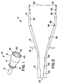
- FIG 1 is a perspective view and Figure 2 is a side plan view of an antenna feed horn 10, according to the invention.
- the feed horn 10 would be one of a plurality of antenna feed horns associated with an antenna array used in connection with a satellite communications network that is operating, for example, in the Ka frequency band.
- the antenna system can take on any suitable configuration and optical geometry for this type of communications network, such as a side-fed antenna system, a front-fed antenna system, a cassegrain antenna system, and a Gregorian antenna system.
- the design of the feed horn 10 is not limited to a particular communications network or antenna system, but has a wider application for many types of communications systems and networks.
- the discussion of the feed horn 10 below will be directed to using the feed horn for the downlink signal of the satellite communications network.
- the feed horn 10 also has reception capabilities for receiving a signal transmitted from the Earth to the satellite on a satellite uplink.
- the feed horn 10 will transmit a signal having a frequency consistent with the communications network, such as the Ka frequency bandwidth, but can be used for any applicable frequency bandwidth, both commercial and military, including the Ku-band.
- the antenna feed horn 10 includes a throat section 12, a profile section 14 and an aperture section 16 connected together to form a single unit.
- An input end of the throat section 12 would be connected to a signal waveguide (not shown), which would be connected to a beam generating system (not shown), as would be well understood to those skilled in the art.
- the signal travels from the waveguide through the throat section 12 and expands through the profile section 14.
- the expanded signal then exits the feed horn 10 at an aperture mouth 20 opposite to the throat section 12.
- An annular mounting flange 18 encircles the profile section 14 and provides a mechanism for mounting the horn 10 to an antenna support structure (not shown).
- the configuration of the inside of the horn 10 provides propagation of desirable incident TE and TM modes at the horn aperture while suppressing undesirable interfering sidelobes, and generates substantially equal E-plane and H-plane beamwidths with low cross-polarization and low phase center variation across a relatively wide bandwidth.
- the outer surface of the throat section 12 is cylindrical, and an internal surface of the throat section 12 includes a cylindrical throat portion 22 proximate an input end 24 of the horn 10.
- the signal traveling through the cylindrical portion 22 expands in a first expanding throat transition portion 26 connected to the cylindrical portion 22 and a second expanding throat transition portion 28 connected to the transition portion 26, as shown.
- the first and second expanding portions 26 and 28 gradually widen the opening of the feed horn 10 from the input end 24, so that the combination of the throat portions 22, 26 and 28 act to lower the cross-polarization of the frequency signal to lessen interference between adjacent beams generated by the antenna system.
- the expanding portions 26 and 28 are specially designed to be different and have the shape as shown to provide this function.
- the expanding portion 28 continues to expand into the profile section 14.
- the profile section 14 has an outer conical surface and an inner profile surface 30 defined by a sine-squared function. The advantage of choosing a profile geometry is in providing a horn that is compact in size, shorter in length and thus lower in weight.
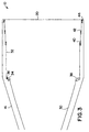
- FIG. 3 is an enlarged side plan view of the aperture section 16.
- the outer surface of the aperture section 16 is cylindrical in shape.
- An aperture inner surface 32 of the aperture section 16 is generally cylindrical in shape, and includes a series of strategically configured and positioned chokes, according to the invention.
- a first choke 34 and a second choke 36 are formed at the transition location between the inner profile surface 30 and the inner aperture surface 32.
- Both of the chokes 34 and 36 are annular notches formed in the inner surface 32 of the horn 10 that have radial and axial dimensions selected by a horn optimization process depending on the frequency and bandwidth of the signal desired.
- the chokes 34 and 36 are adjacent to each other and separated by a common wall 38, where the annular choke 36 has a larger diameter and is outside of the annular choke 34.
- the discontinuity in the inner surface of the horn 10 provided by the chokes 34 and 36 causes higher propagating modes to be generated for increased signal bandwidth.
- the inner surface 32 of the aperture section 16 also includes chokes 40, 42 and 44 proximate the mouth 20 of the aperture section 16.
- the choke 44 is formed in the end of the horn 10 at the mouth 20, and the chokes 40 and 42 are formed in the surface 32, as shown.
- Each of the chokes 40, 42 and 44 are also annular notches having radial and axial dimensions, where the diameter of the choke increases from the choke 40 to the choke 44, as shown.
- the chokes 40, 42 and 44 are spaced apart from each other a predetermined amount, as shown, and have a narrower radial dimension than the chokes 34 and 36.
- the chokes 40, 42 and 44 act to absorb surface currents in the aperture section 16 proximate the mouth 20 to help equalize the E-plane and H-plane beamwidths, suppress the sidelobes and lower the cross-polarization.
- the chokes 34, 36, 40, 42 and 44 combine to control the mode content at the mouth 20 to provide an output signal that has low cross-polarization, low sidelobes, is circularly polarized and has a 10% or more operational bandwidth.
- the internal diameter of the throat section 12 relative to the wavelength ⁇ of the signal being transmitted only allows propagation of the lower TE 11 mode. Propagation of the TE 11 modes limits the E-plane beamwidth, and thus does not allow propagation of substantially equal E-plane and H-plane beamwidths necessary for circular polarization. This creates a large axial ratio causing the signal to be elliptically polarized, as discussed above, reducing signal strength and increasing data rate loss.
- a discontinuity must be provided within the horn 10 that expands the propagation diameter of the horn 10.
- the chokes 34, 36, 40, 42 and 44 provide this discontinuity.
- the combination of the chokes 34, 36, 40, 42 and 44 allows the designer of the horn 10 to optimize the weighting of higher order modes by providing the necessary phase and amplitude relationships between these higher modes for increased bandwidth.
- the chokes 34, 36, 40, 42 and 44 give the flexibility to provide phase and amplitude matching for the propagating modes over a wider bandwidth, on the order of 10%-20%, at the mouth 20.
- the location of the chokes 34, 36, 40, 42 and 44, as well as the radial and axial dimensions of the chokes 34, 36, 40, 42 and 44, is experimentally optimized to provide the desirable phase and amplitude matching of the mode content at the horn aperture for this purpose.
- This control of the mode content provides for minimizing the length of the feed horn 10, maximizing the size of the mouth 20 at the desired operational bandwidth, and provide radiation patterns with equal E- and H-plane beamdwidths, suppressed sidelobes and low-cross polarization. Additional chokes may also be provided within the horn 10 to further optimize the signal propagation consistent with the discussion above.
Landscapes
- Waveguide Aerials (AREA)
- Variable-Direction Aerials And Aerial Arrays (AREA)
- Aerials With Secondary Devices (AREA)
- Details Of Aerials (AREA)
Applications Claiming Priority (2)
| Application Number | Priority Date | Filing Date | Title |
|---|---|---|---|
| US09/351,896 US6208310B1 (en) | 1999-07-13 | 1999-07-13 | Multimode choked antenna feed horn |
| US351896 | 1999-07-13 |
Publications (2)
| Publication Number | Publication Date |
|---|---|
| EP1069648A2 true EP1069648A2 (fr) | 2001-01-17 |
| EP1069648A3 EP1069648A3 (fr) | 2002-07-31 |
Family
ID=23382884
Family Applications (1)
| Application Number | Title | Priority Date | Filing Date |
|---|---|---|---|
| EP00114022A Withdrawn EP1069648A3 (fr) | 1999-07-13 | 2000-07-04 | Cornet d'alimentation à mode multiple avec une structure piège |
Country Status (4)
| Country | Link |
|---|---|
| US (1) | US6208310B1 (fr) |
| EP (1) | EP1069648A3 (fr) |
| JP (1) | JP2001044742A (fr) |
| CA (1) | CA2311015C (fr) |
Cited By (3)
| Publication number | Priority date | Publication date | Assignee | Title |
|---|---|---|---|---|
| RU2630845C1 (ru) * | 2016-06-14 | 2017-09-13 | Общество с ограниченной ответственностью "Даурия - спутниковые технологии" | Компактный высокоскоростной радиопередающий комплекс космического аппарата |
| CN109119764A (zh) * | 2018-09-28 | 2019-01-01 | 江苏亨通太赫兹技术有限公司 | 一种双圆极化馈源天线 |
| CN114639964A (zh) * | 2022-03-09 | 2022-06-17 | 四创电子股份有限公司 | 一种一体化单脉冲测控雷达天线的可折叠馈源系统 |
Families Citing this family (31)
| Publication number | Priority date | Publication date | Assignee | Title |
|---|---|---|---|---|
| US6396453B2 (en) | 2000-04-20 | 2002-05-28 | Ems Technologies Canada, Ltd. | High performance multimode horn |
| US6577283B2 (en) * | 2001-04-16 | 2003-06-10 | Northrop Grumman Corporation | Dual frequency coaxial feed with suppressed sidelobes and equal beamwidths |
| US6504514B1 (en) * | 2001-08-28 | 2003-01-07 | Trw Inc. | Dual-band equal-beam reflector antenna system |
| US6642900B2 (en) | 2001-09-21 | 2003-11-04 | The Boeing Company | High radiation efficient dual band feed horn |
| ES2204288B1 (es) * | 2002-05-24 | 2005-07-16 | Universidad Publica De Navarra. | Antena de bocina que combina corrugaciones horizontales y verticales. |
| US6618021B1 (en) * | 2002-06-12 | 2003-09-09 | The Boeing Company | Electrically small aperture antennae with field minimization |
| US20040222934A1 (en) * | 2003-05-06 | 2004-11-11 | Northrop Grumman Corporation | Multi-mode, multi-choke feed horn |
| US7161550B2 (en) * | 2004-04-20 | 2007-01-09 | Tdk Corporation | Dual- and quad-ridged horn antenna with improved antenna pattern characteristics |
| US7511678B2 (en) * | 2006-02-24 | 2009-03-31 | Northrop Grumman Corporation | High-power dual-frequency coaxial feedhorn antenna |
| US7852277B2 (en) * | 2007-08-03 | 2010-12-14 | Lockheed Martin Corporation | Circularly polarized horn antenna |
| US8026859B2 (en) * | 2008-08-07 | 2011-09-27 | Tdk Corporation | Horn antenna with integrated impedance matching network for improved operating frequency range |
| US9496620B2 (en) | 2013-02-04 | 2016-11-15 | Ubiquiti Networks, Inc. | Radio system for long-range high-speed wireless communication |
| US8836601B2 (en) | 2013-02-04 | 2014-09-16 | Ubiquiti Networks, Inc. | Dual receiver/transmitter radio devices with choke |
| US8184061B2 (en) * | 2009-09-16 | 2012-05-22 | Ubiquiti Networks | Antenna system and method |
| US20150244077A1 (en) | 2014-02-25 | 2015-08-27 | Ubiquiti Networks Inc. | Antenna system and method |
| US9543635B2 (en) | 2013-02-04 | 2017-01-10 | Ubiquiti Networks, Inc. | Operation of radio devices for long-range high-speed wireless communication |
| US9397820B2 (en) | 2013-02-04 | 2016-07-19 | Ubiquiti Networks, Inc. | Agile duplexing wireless radio devices |
| US9531067B2 (en) | 2013-02-08 | 2016-12-27 | Ubiquiti Networks, Inc. | Adjustable-tilt housing with flattened dome shape, array antenna, and bracket mount |
| EP3648359B1 (fr) | 2013-10-11 | 2024-12-11 | Ubiquiti Inc. | Optimisation de système radio sans fil par analyse continue du spectre |
| US9325516B2 (en) | 2014-03-07 | 2016-04-26 | Ubiquiti Networks, Inc. | Power receptacle wireless access point devices for networked living and work spaces |
| PL3114884T3 (pl) | 2014-03-07 | 2020-05-18 | Ubiquiti Inc. | Uwierzytelnianie i identyfikacja urządzenia w chmurze |
| US9843096B2 (en) | 2014-03-17 | 2017-12-12 | Ubiquiti Networks, Inc. | Compact radio frequency lenses |
| DK3127187T3 (da) | 2014-04-01 | 2021-02-08 | Ubiquiti Inc | Antenneanordning |
| US9431715B1 (en) | 2015-08-04 | 2016-08-30 | Northrop Grumman Systems Corporation | Compact wide band, flared horn antenna with launchers for generating circular polarized sum and difference patterns |
| US11103925B2 (en) * | 2018-03-22 | 2021-08-31 | The Boeing Company | Additively manufactured antenna |
| US10892549B1 (en) | 2020-02-28 | 2021-01-12 | Northrop Grumman Systems Corporation | Phased-array antenna system |
| US11909110B2 (en) | 2020-09-30 | 2024-02-20 | The Boeing Company | Additively manufactured mesh horn antenna |
| USD1003875S1 (en) * | 2021-04-15 | 2023-11-07 | Nan Hu | Corrugated feed horn antenna |
| USD1008234S1 (en) * | 2021-04-21 | 2023-12-19 | Nan Hu | Corrugated feed horn antenna |
| USD1006800S1 (en) * | 2021-04-29 | 2023-12-05 | Nan Hu | Dual linear polarization conical horn antenna |
| CN115458912A (zh) * | 2022-08-31 | 2022-12-09 | 西安电子科技大学 | 一种高隔离度的双喇叭天线结构 |
Family Cites Families (6)
| Publication number | Priority date | Publication date | Assignee | Title |
|---|---|---|---|---|
| US3898669A (en) * | 1973-05-15 | 1975-08-05 | Us Air Force | Apparatus for providing higher order mode compensation in horn antennas |
| US4658258A (en) * | 1983-11-21 | 1987-04-14 | Rca Corporation | Taperd horn antenna with annular choke channel |
| US4731616A (en) * | 1985-06-03 | 1988-03-15 | Fulton David A | Antenna horns |
| US4792814A (en) * | 1986-10-23 | 1988-12-20 | Mitsubishi Denki Kabushiki Kaisha | Conical horn antenna applicable to plural modes of electromagnetic waves |
| US5486839A (en) * | 1994-07-29 | 1996-01-23 | Winegard Company | Conical corrugated microwave feed horn |
| US6208309B1 (en) * | 1999-03-16 | 2001-03-27 | Trw Inc. | Dual depth aperture chokes for dual frequency horn equalizing E and H-plane patterns |
-
1999
- 1999-07-13 US US09/351,896 patent/US6208310B1/en not_active Expired - Fee Related
-
2000
- 2000-06-08 CA CA002311015A patent/CA2311015C/fr not_active Expired - Fee Related
- 2000-07-04 EP EP00114022A patent/EP1069648A3/fr not_active Withdrawn
- 2000-07-05 JP JP2000203425A patent/JP2001044742A/ja not_active Ceased
Cited By (5)
| Publication number | Priority date | Publication date | Assignee | Title |
|---|---|---|---|---|
| RU2630845C1 (ru) * | 2016-06-14 | 2017-09-13 | Общество с ограниченной ответственностью "Даурия - спутниковые технологии" | Компактный высокоскоростной радиопередающий комплекс космического аппарата |
| WO2017217893A1 (fr) * | 2016-06-14 | 2017-12-21 | Общество С Ограниченной Ответственностью "Даурия – Спутниковые Технологии" | Complexe compact de transmission radio haut débit pour véhicule spatial |
| CN109119764A (zh) * | 2018-09-28 | 2019-01-01 | 江苏亨通太赫兹技术有限公司 | 一种双圆极化馈源天线 |
| CN114639964A (zh) * | 2022-03-09 | 2022-06-17 | 四创电子股份有限公司 | 一种一体化单脉冲测控雷达天线的可折叠馈源系统 |
| CN114639964B (zh) * | 2022-03-09 | 2024-05-31 | 四创电子股份有限公司 | 一种一体化单脉冲测控雷达天线的可折叠馈源系统 |
Also Published As
| Publication number | Publication date |
|---|---|
| CA2311015A1 (fr) | 2001-01-13 |
| JP2001044742A (ja) | 2001-02-16 |
| EP1069648A3 (fr) | 2002-07-31 |
| US6208310B1 (en) | 2001-03-27 |
| CA2311015C (fr) | 2003-02-25 |
Similar Documents
| Publication | Publication Date | Title |
|---|---|---|
| US6208310B1 (en) | Multimode choked antenna feed horn | |
| US6967627B2 (en) | High radiation efficient dual band feed horn | |
| US7034771B2 (en) | Multi-beam and multi-band antenna system for communication satellites | |
| US8957821B1 (en) | Dual-band feed horn with common beam widths | |
| EP1152484B1 (fr) | Cornet à mode multiple à performances elevées | |
| US7236681B2 (en) | Feed assembly for multi-beam antenna with non-circular reflector, and such an assembly that is field-switchable between linear and circular polarization modes | |
| US6163304A (en) | Multimode, multi-step antenna feed horn | |
| EP1037305B1 (fr) | Antenne cornet pour deux fréquences avec une structure piège à deux profondeurs pour égalisation de diagrammes de rayonnement dans les plans E et H | |
| US6480165B2 (en) | Multibeam antenna for establishing individual communication links with satellites positioned in close angular proximity to each other | |
| US8164533B1 (en) | Horn antenna and system for transmitting and/or receiving radio frequency signals in multiple frequency bands | |
| US7463207B1 (en) | High-efficiency horns for an antenna system | |
| US6384795B1 (en) | Multi-step circular horn system | |
| US6535174B2 (en) | Multi-mode square horn with cavity-suppressed higher-order modes | |
| US6577283B2 (en) | Dual frequency coaxial feed with suppressed sidelobes and equal beamwidths | |
| US20040222934A1 (en) | Multi-mode, multi-choke feed horn | |
| EP1267445A1 (fr) | Antenne cornet multimode | |
| US20020126063A1 (en) | Rectangular paraboloid truncation wall | |
| US20240413532A1 (en) | Nested concentric coaxial feed assembly for ground antennas supporting multiple frequency bands | |
| Claydon | Earth-station and satellite antennas | |
| JPS623510A (ja) | 多周波数帯共用アンテナ装置 |
Legal Events
| Date | Code | Title | Description |
|---|---|---|---|
| PUAI | Public reference made under article 153(3) epc to a published international application that has entered the european phase |
Free format text: ORIGINAL CODE: 0009012 |
|
| AK | Designated contracting states |
Kind code of ref document: A2 Designated state(s): AT BE CH CY DE DK ES FI FR GB GR IE IT LI LU MC NL PT SE |
|
| AX | Request for extension of the european patent |
Free format text: AL;LT;LV;MK;RO;SI |
|
| PUAL | Search report despatched |
Free format text: ORIGINAL CODE: 0009013 |
|
| AK | Designated contracting states |
Kind code of ref document: A3 Designated state(s): AT BE CH CY DE DK ES FI FR GB GR IE IT LI LU MC NL PT SE |
|
| AX | Request for extension of the european patent |
Free format text: AL;LT;LV;MK;RO;SI |
|
| 17P | Request for examination filed |
Effective date: 20030108 |
|
| 17Q | First examination report despatched |
Effective date: 20030206 |
|
| AKX | Designation fees paid |
Designated state(s): DE FR GB IT |
|
| GRAP | Despatch of communication of intention to grant a patent |
Free format text: ORIGINAL CODE: EPIDOSNIGR1 |
|
| RAP1 | Party data changed (applicant data changed or rights of an application transferred) |
Owner name: NORTHROP GRUMMAN CORPORATION |
|
| RAP1 | Party data changed (applicant data changed or rights of an application transferred) |
Owner name: NORTHROP GRUMMAN CORPORATION |
|
| STAA | Information on the status of an ep patent application or granted ep patent |
Free format text: STATUS: THE APPLICATION IS DEEMED TO BE WITHDRAWN |
|
| 18D | Application deemed to be withdrawn |
Effective date: 20031230 |