EP1069647B1 - Antenna having a helical antenna element extending along a cylindrical flexible substrate - Google Patents
Antenna having a helical antenna element extending along a cylindrical flexible substrate Download PDFInfo
- Publication number
- EP1069647B1 EP1069647B1 EP99113715A EP99113715A EP1069647B1 EP 1069647 B1 EP1069647 B1 EP 1069647B1 EP 99113715 A EP99113715 A EP 99113715A EP 99113715 A EP99113715 A EP 99113715A EP 1069647 B1 EP1069647 B1 EP 1069647B1
- Authority
- EP
- European Patent Office
- Prior art keywords
- antenna
- helical
- flexible substrate
- conductive patterns
- sleeve
- Prior art date
- Legal status (The legal status is an assumption and is not a legal conclusion. Google has not performed a legal analysis and makes no representation as to the accuracy of the status listed.)
- Expired - Lifetime
Links
- 239000000758 substrate Substances 0.000 title claims description 32
- 238000004519 manufacturing process Methods 0.000 description 8
- 239000012212 insulator Substances 0.000 description 7
- 238000006073 displacement reaction Methods 0.000 description 5
- 230000008878 coupling Effects 0.000 description 4
- 238000010168 coupling process Methods 0.000 description 4
- 238000005859 coupling reaction Methods 0.000 description 4
- 230000015572 biosynthetic process Effects 0.000 description 3
- 238000000034 method Methods 0.000 description 3
- 230000002411 adverse Effects 0.000 description 2
- 239000004020 conductor Substances 0.000 description 2
- 239000012811 non-conductive material Substances 0.000 description 2
- 230000002093 peripheral effect Effects 0.000 description 2
- 239000004677 Nylon Substances 0.000 description 1
- 230000000694 effects Effects 0.000 description 1
- 238000010295 mobile communication Methods 0.000 description 1
- 229920001778 nylon Polymers 0.000 description 1
- 239000011347 resin Substances 0.000 description 1
- 229920005989 resin Polymers 0.000 description 1
- 238000005476 soldering Methods 0.000 description 1
- 238000003466 welding Methods 0.000 description 1
Images
Classifications
-
- H—ELECTRICITY
- H01—ELECTRIC ELEMENTS
- H01Q—ANTENNAS, i.e. RADIO AERIALS
- H01Q1/00—Details of, or arrangements associated with, antennas
- H01Q1/36—Structural form of radiating elements, e.g. cone, spiral, umbrella; Particular materials used therewith
-
- H—ELECTRICITY
- H01—ELECTRIC ELEMENTS
- H01Q—ANTENNAS, i.e. RADIO AERIALS
- H01Q1/00—Details of, or arrangements associated with, antennas
- H01Q1/12—Supports; Mounting means
- H01Q1/22—Supports; Mounting means by structural association with other equipment or articles
- H01Q1/24—Supports; Mounting means by structural association with other equipment or articles with receiving set
- H01Q1/241—Supports; Mounting means by structural association with other equipment or articles with receiving set used in mobile communications, e.g. GSM
- H01Q1/242—Supports; Mounting means by structural association with other equipment or articles with receiving set used in mobile communications, e.g. GSM specially adapted for hand-held use
-
- H—ELECTRICITY
- H01—ELECTRIC ELEMENTS
- H01Q—ANTENNAS, i.e. RADIO AERIALS
- H01Q1/00—Details of, or arrangements associated with, antennas
- H01Q1/12—Supports; Mounting means
- H01Q1/22—Supports; Mounting means by structural association with other equipment or articles
- H01Q1/24—Supports; Mounting means by structural association with other equipment or articles with receiving set
- H01Q1/241—Supports; Mounting means by structural association with other equipment or articles with receiving set used in mobile communications, e.g. GSM
- H01Q1/242—Supports; Mounting means by structural association with other equipment or articles with receiving set used in mobile communications, e.g. GSM specially adapted for hand-held use
- H01Q1/243—Supports; Mounting means by structural association with other equipment or articles with receiving set used in mobile communications, e.g. GSM specially adapted for hand-held use with built-in antennas
-
- H—ELECTRICITY
- H01—ELECTRIC ELEMENTS
- H01Q—ANTENNAS, i.e. RADIO AERIALS
- H01Q1/00—Details of, or arrangements associated with, antennas
- H01Q1/12—Supports; Mounting means
- H01Q1/22—Supports; Mounting means by structural association with other equipment or articles
- H01Q1/24—Supports; Mounting means by structural association with other equipment or articles with receiving set
- H01Q1/241—Supports; Mounting means by structural association with other equipment or articles with receiving set used in mobile communications, e.g. GSM
- H01Q1/242—Supports; Mounting means by structural association with other equipment or articles with receiving set used in mobile communications, e.g. GSM specially adapted for hand-held use
- H01Q1/243—Supports; Mounting means by structural association with other equipment or articles with receiving set used in mobile communications, e.g. GSM specially adapted for hand-held use with built-in antennas
- H01Q1/244—Supports; Mounting means by structural association with other equipment or articles with receiving set used in mobile communications, e.g. GSM specially adapted for hand-held use with built-in antennas extendable from a housing along a given path
-
- H—ELECTRICITY
- H01—ELECTRIC ELEMENTS
- H01Q—ANTENNAS, i.e. RADIO AERIALS
- H01Q1/00—Details of, or arrangements associated with, antennas
- H01Q1/36—Structural form of radiating elements, e.g. cone, spiral, umbrella; Particular materials used therewith
- H01Q1/362—Structural form of radiating elements, e.g. cone, spiral, umbrella; Particular materials used therewith for broadside radiating helical antennas
-
- H—ELECTRICITY
- H01—ELECTRIC ELEMENTS
- H01Q—ANTENNAS, i.e. RADIO AERIALS
- H01Q11/00—Electrically-long antennas having dimensions more than twice the shortest operating wavelength and consisting of conductive active radiating elements
- H01Q11/02—Non-resonant antennas, e.g. travelling-wave antenna
- H01Q11/08—Helical antennas
-
- H—ELECTRICITY
- H01—ELECTRIC ELEMENTS
- H01Q—ANTENNAS, i.e. RADIO AERIALS
- H01Q11/00—Electrically-long antennas having dimensions more than twice the shortest operating wavelength and consisting of conductive active radiating elements
- H01Q11/02—Non-resonant antennas, e.g. travelling-wave antenna
- H01Q11/08—Helical antennas
- H01Q11/083—Tapered helical aerials, e.g. conical spiral aerials
Definitions
- This invention relates to an antenna for use in a mobile communication apparatus such as a mobile telephone set and, in particular, to an antenna in which an antenna base element arranged in an antenna top has a flexible structure.
- the helical antenna is manufactured in the following manner. At first, an antenna base element is prepared which has a one-end portion provided with a helical coil guide made of a nonconductive material and the other-end portion coupled to a sleeve made of a conductive material.
- the sleeve has a sleeve-helical coupling portion and a flange portion and serves as a feeding portion.
- a helical antenna element having an antenna function is screwed onto the helical coil guide and is brought into contact with the flange portion of the sleeve so as to be electrically fed from the sleeve.
- an antenna top is molded to cover the one-end portion of the antenna base element and the flange portion of the sleeve.
- the separate antenna is manufactured.
- a whip antenna element is mechanically fixed to the other-end portion of the antenna base element before the above-mentioned antenna top is molded.
- the whip antenna element is supported at its one end by an insulator forming a body of the antenna base element and extending through an inner bore of the sleeve.
- the helical antenna element is screwed onto the helical coil guide and is brought into contact with the flange portion of the sleeve so as to be electrically fed from the sleeve.
- the antenna top is molded to cover the one-end portion of the antenna base element and the flange portion.
- the whip antenna element is covered with a face tube for protection and smart appearance.
- a holder is attached so as to be slidable on the outer peripheral surface of the face tube.
- a stopper is attached to the whip antenna element at the other end thereof opposite to the one end fixed to the insulator.
- the helical antenna element Upon manufacture of the helical antenna or the separate antenna described above, it is required to screw the helical antenna element of a predetermined diameter onto the helical coil guide. During any operation in the overall manufacturing process up to the formation of the antenna top, the helical antenna element may be deformed or displaced under some external force. In this event, antenna characteristics will be adversely affected.
- each of the helical antenna element and the helical coil guide is accurately selected so that the helical antenna element is exactly fitted to the helical coil guide to be prevented from easy movement out of its proper position.
- JP-A Japanese Unexamined Patent Publications
- a helical antenna according to the preamble of claim 1 is known from US 4,945,363.
- the flexible substrate has end portions facing to each other in the cylindrical shape, each of the oblique conductive patters extending between the end portions.
- the oblique conductive patterns are parallel to one another.
- the oblique conductive patterns may have a pitch similar therebetween.
- the oblique conductive patterns may have a width similar to one another.
- the antenna further comprises an antenna top containing the flexible substrate of the cylindrical shape.
- the antenna further comprises a conductive sleeve fitted as a feeding portion to the flexible substrate of the cylindrical shape.
- the flexible substrate has a feeding contact formed on one of two remaining sides thereof to be electrically connected to the sleeve.
- an antenna base element is prepared.
- the antenna base element has a one-end portion provided with a helical coil guide 11 made of a nonconductive material such as nylon and the other-end portion coupled to a sleeve 5 made of a conductive material.
- the sleeve 5 has a sleeve-helical coupling portion 6 and a flange portion and serves as a feeding portion.
- a helical antenna element 40 of a helical shape is screwed onto the helical coil guide 11 and is brought into contact with the flange portion of the sleeve 5.
- the helical antenna element 40 is electrically fed through the sleeve 5 to have an antenna function. Finally, in order to protect the helical antenna element 40 and to improve a commercial value in design, an antenna top (not shown) is molded to cover the one-end portion of the antenna base element and the flange portion of the sleeve. Thus, the helical antenna is completed.
- a whip antenna element 9 is mechanically fixed to the other-end portion of the antenna base element before the above-mentioned antenna top is molded. More in detail, the whip antenna element 9 is supported at its one end by an insulator 7 forming a body of the antenna base element and extending through an inner bore of the sleeve 5.
- the helical antenna element 40 is screwed onto the helical coil guide 11 and is brought into contact with the flange portion of the sleeve 5 so as to be electrically fed from the sleeve 5. Thereafter, the antenna top 10 is molded to cover the one-end portion of the antenna base element and the flange portion.
- the whip antenna element 9 is covered with a face tube 8 for protection and smart appearance.
- a holder (not shown) is attached so as to be slidable on the outer peripheral surface of the face tube 8.
- a stopper (not shown) is attached to the whip antenna element 9 at the other end thereof opposite to the one end fixed to the insulator 7.
- the holder serves to attach the antenna to a housing of a radio apparatus.
- the stopper is engaged with the holder to maintain an extended condition of the antenna.
- the antenna top 10 may be replaced by an antenna cap preliminarily formed so as to achieve a similar function. In this event, the cap is simply fitted to cover the antenna base element.
- each of the helical antenna element 40 and the helical coil guide 11 is accurately selected so that the helical antenna element 40 is exactly fitted to the helical coil guide 11 to be prevented from easy movement out of its proper position.
- An antenna according to one embodiment of this invention comprises an antenna base element having one-end portion arranged in an antenna top and the other-end portion fitted and connected to a part of a sleeve as a feeding portion, like in the conventional antenna described above.
- the antenna base element comprises a flexible substrate 1.
- the flexible substrate 1 is provided with a plurality of oblique conductive patterns 4 printed thereon.
- the oblique conductive patterns 4 have a same width and extend from one side to the other side of the flexible substrate 1 in parallel to one another at a same pitch.
- the flexible substrate 1 has a plurality of contact pin terminals 3 formed at one ends of the oblique conductive patterns 4 on the one side of the flexible substrate 1 and a plurality of contact receptacle terminals 12 formed at the other ends of the oblique conductive patterns 4 on the other side of the flexible substrate 1.
- the flexible substrate 1 is provided with a feeding contact 2 formed on one of two remaining sides thereof to be electrically connected to the sleeve 5 when the antenna base element is fitted and bonded to the above-mentioned part of the sleeve 5.
- the flexible substrate 1 illustrated in Fig. 3 is rounded to form a cylindrical shape.
- the one side and the other side of the flexible substrate 1 are fixedly bonded to each other by soldering or welding to form the antenna base element.
- the contact pin terminals 3 and the contact receptacle terminals 12 of the flexible substrate 1 are connected to each other in one-to-one correspondence.
- a combination of the oblique conductive patterns 4 extends along a helical shape and forms a helical conductive pattern having an antenna function similar to the helical antenna element 40 of the antenna illustrated in Fig. 2.
- a separate antenna comprises the antenna base element with the feeding contact 2 of the flexible substrate 1 connected to a part of the sleeve 5 (specifically, a sleeve-helical coupling portion 6 described in conjunction with Figs. 1 and 2).
- a whip antenna element 9 is mechanically fixed by the insulator 7 that extends through the sleeve 5 fitted thereto.
- an antenna top 10 is formed to cover the one-end portion of the antenna base element and the flange portion of the sleeve 5. Then, a face tube 8 for protection and smart appearance is attached to cover the whip antenna element 9 coupled to the other end of the insulator 7. Thus, the separate antenna is completed.
- the flexible substrate 1 as the antenna base element of a flexible structure has the oblique conductive patterns 4 forming the helical conductive pattern equivalent in function to the helical antenna element of the conventional antenna. Therefore, manufacture or assembling is easily carried out without deformation or displacement of the helical conductive pattern which is printed on the flexible substrate 1. As a result, stable electrical characteristics are achieved.
- the contact pin terminals 3 protrude outwards in a radial direction when the flexible substrate 1 is rounded and bonded.
- the contact pin terminals 3 may protrude inwards provided that a plurality of pin escape grooves are formed in the insulator 7 to serve as helical guides for the contact pin terminals 3. In this event, coupling between the contact pin terminals 3 and the pin escape grooves prevents the rotation of the flexible substrate 1 so that antenna characteristics are further stabilized.
- the separate antenna has been directed to the separate antenna. It is noted here that this invention is also applicable to an integral-type antenna (all of the helical antenna, the sleeve 5, and the whip antenna element 9 are electrically connected) and a fixed antenna (only the helical antenna exhibits the antenna function) to achieve the similar effect.
- the helical antenna is achieved by the helical conductive pattern formed by a combination of the oblique conductive patterns 4.
- the antenna base element has a flexible structure achieved by the flexible substrate 1.
- the flexible substrate 1 is rounded in a cylindrical shape so that the oblique conductive patterns 4 printed thereon are combined and electrically connected to form the helical conductive pattern equivalent to the helical antenna element 40 in the conventional antenna.
- the antenna can be easily and economically assembled and manufactured without displacement or deformation and is therefore stable in electrical characteristics and high in reliability.
Landscapes
- Engineering & Computer Science (AREA)
- Computer Networks & Wireless Communication (AREA)
- Details Of Aerials (AREA)
- Support Of Aerials (AREA)
Description
- This invention relates to an antenna for use in a mobile communication apparatus such as a mobile telephone set and, in particular, to an antenna in which an antenna base element arranged in an antenna top has a flexible structure.
- As a conventional antenna of the type, use is typically made of a helical antenna and a separate antenna comprising the helical antenna. For example, the helical antenna is manufactured in the following manner. At first, an antenna base element is prepared which has a one-end portion provided with a helical coil guide made of a nonconductive material and the other-end portion coupled to a sleeve made of a conductive material. The sleeve has a sleeve-helical coupling portion and a flange portion and serves as a feeding portion. Then, a helical antenna element having an antenna function is screwed onto the helical coil guide and is brought into contact with the flange portion of the sleeve so as to be electrically fed from the sleeve. Finally, in order to protect the helical antenna element and to improve a commercial value in design, an antenna top is molded to cover the one-end portion of the antenna base element and the flange portion of the sleeve.
- By the use of the above-mentioned antenna base element, the separate antenna is manufactured. Specifically, a whip antenna element is mechanically fixed to the other-end portion of the antenna base element before the above-mentioned antenna top is molded. More in detail, the whip antenna element is supported at its one end by an insulator forming a body of the antenna base element and extending through an inner bore of the sleeve. The helical antenna element is screwed onto the helical coil guide and is brought into contact with the flange portion of the sleeve so as to be electrically fed from the sleeve. Thereafter, the antenna top is molded to cover the one-end portion of the antenna base element and the flange portion. Subsequently, the whip antenna element is covered with a face tube for protection and smart appearance. Around the face tube, a holder is attached so as to be slidable on the outer peripheral surface of the face tube. A stopper is attached to the whip antenna element at the other end thereof opposite to the one end fixed to the insulator.
- Upon manufacture of the helical antenna or the separate antenna described above, it is required to screw the helical antenna element of a predetermined diameter onto the helical coil guide. During any operation in the overall manufacturing process up to the formation of the antenna top, the helical antenna element may be deformed or displaced under some external force. In this event, antenna characteristics will be adversely affected.
- In order to avoid the above-mentioned situation, the size of each of the helical antenna element and the helical coil guide is accurately selected so that the helical antenna element is exactly fitted to the helical coil guide to be prevented from easy movement out of its proper position.
- However, in order to fit the helical antenna element of such a size accurately selected as described above to the helical coil guide, delicate and skillful work is required. In addition, it is difficult to completely prevent the deformation or the displacement of the helical antenna element: As a result, the production cost is inevitably increased in order to provide good products excellent in antenna characteristics and high in reliability.
- For example, existing techniques related to the helical antenna and the separate antenna are disclosed in Japanese Unexamined Patent Publications (JP-A) Nos. 5-243829 (243829/1993) and 7-99404 (99404/1995).
- A helical antenna according to the preamble of claim 1 is known from US 4,945,363.
- It is an object of the present invention to provide an antenna which can be easily and economically manufactured and is highly reliable without deformation and displacement during manufacture.
- Other objects of the present invention will become clear as the description proceeds.
- The object is solved by an antenna according to claim 1.
- It may be arranged that the flexible substrate has end portions facing to each other in the cylindrical shape, each of the oblique conductive patters extending between the end portions.
- It may be arranged that the oblique conductive patterns are parallel to one another.
- It may be arranged that the oblique conductive patterns have a pitch similar therebetween.
- It may be arranged that the oblique conductive patterns have a width similar to one another.
- It may be arranged that the antenna further comprises an antenna top containing the flexible substrate of the cylindrical shape.
- It may be arranged that the antenna further comprises a conductive sleeve fitted as a feeding portion to the flexible substrate of the cylindrical shape.
- It may be arranged that the flexible substrate has a feeding contact formed on one of two remaining sides thereof to be electrically connected to the sleeve.
-
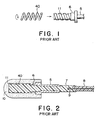
- Fig. 1 is a side view of a characteristic part of a conventional helical antenna;
- Fig. 2 is a side sectional view of a conventional separate antenna using the helical antenna illustrated in Fig. 1;
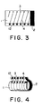
- Fig. 3 is a plan view of a flexible substrate to form an antenna base element of an antenna according to one embodiment of this invention;
- Fig. 4 is a perspective view of the flexible substrate illustrated in Fig. 3 when it is rounded in a cylindrical shape;
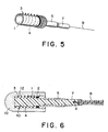
- Fig. 5 is a perspective view of a separate antenna comprising the antenna base element with the flexible substrate in Fig. 4 connected to a part of a sleeve; and
- Fig. 6 is a side sectional view of the separate antenna illustrated in Fig. 5.
-
- In order to facilitate an understanding of the present invention, description will at first be made about conventional antennas with reference to Figs. 1 and 2.
- Referring to Fig. 1, a process of producing a conventional helical antenna will be described. At first, an antenna base element is prepared. The antenna base element has a one-end portion provided with a helical coil guide 11 made of a nonconductive material such as nylon and the other-end portion coupled to a
sleeve 5 made of a conductive material. Thesleeve 5 has a sleeve-helical coupling portion 6 and a flange portion and serves as a feeding portion. Then, ahelical antenna element 40 of a helical shape is screwed onto the helical coil guide 11 and is brought into contact with the flange portion of thesleeve 5. Thehelical antenna element 40 is electrically fed through thesleeve 5 to have an antenna function. Finally, in order to protect thehelical antenna element 40 and to improve a commercial value in design, an antenna top (not shown) is molded to cover the one-end portion of the antenna base element and the flange portion of the sleeve. Thus, the helical antenna is completed. - Referring to Fig. 2, a process of producing a conventional separate antenna will be described. A
whip antenna element 9 is mechanically fixed to the other-end portion of the antenna base element before the above-mentioned antenna top is molded. More in detail, thewhip antenna element 9 is supported at its one end by aninsulator 7 forming a body of the antenna base element and extending through an inner bore of thesleeve 5. Thehelical antenna element 40 is screwed onto the helical coil guide 11 and is brought into contact with the flange portion of thesleeve 5 so as to be electrically fed from thesleeve 5. Thereafter, theantenna top 10 is molded to cover the one-end portion of the antenna base element and the flange portion. Subsequently, thewhip antenna element 9 is covered with aface tube 8 for protection and smart appearance. Around theface tube 8, a holder (not shown) is attached so as to be slidable on the outer peripheral surface of theface tube 8. A stopper (not shown) is attached to thewhip antenna element 9 at the other end thereof opposite to the one end fixed to theinsulator 7. Thus, the separate antenna is completed. It is noted here that the holder serves to attach the antenna to a housing of a radio apparatus. When the antenna is extended, the stopper is engaged with the holder to maintain an extended condition of the antenna. Theantenna top 10 may be replaced by an antenna cap preliminarily formed so as to achieve a similar function. In this event, the cap is simply fitted to cover the antenna base element. - Upon manufacture of the helical antenna or the separate antenna described above, it is required to screw the
helical antenna element 40 of a predetermined diameter (for example, = 0.5 mm) onto the helical coil guide 11. During any operation in the overall manufacturing process up to the formation of theantenna top 10 or the fitting of the antenna cap, thehelical antenna element 40 may be deformed or displaced under some external force. Specifically, thehelical antenna element 40 is often deformed or displaced under the pressure of molded resin during the formation of theantenna top 10. In this event, antenna characteristics will be adversely affected. - In order to avoid the above-mentioned situation, the size of each of the
helical antenna element 40 and the helical coil guide 11 is accurately selected so that thehelical antenna element 40 is exactly fitted to the helical coil guide 11 to be prevented from easy movement out of its proper position. - However, in order to fit the
helical antenna element 40 of such a size accurately selected as described above to the helical coil guide 11, delicate and skillful work is required. In addition, it is difficult to completely prevent the deformation or the displacement of thehelical antenna element 40. As a result, the production cost is inevitably increased in order to provide good products excellent in antenna characteristics and high in reliability. - Now, the description will be made in detail about one embodiment of the present invention with reference to the drawing.
- An antenna according to one embodiment of this invention comprises an antenna base element having one-end portion arranged in an antenna top and the other-end portion fitted and connected to a part of a sleeve as a feeding portion, like in the conventional antenna described above. As a characteristic of this invention, the antenna base element comprises a flexible substrate 1.
- Referring to Fig. 3, the flexible substrate 1 is provided with a plurality of oblique
conductive patterns 4 printed thereon. The obliqueconductive patterns 4 have a same width and extend from one side to the other side of the flexible substrate 1 in parallel to one another at a same pitch. The flexible substrate 1 has a plurality ofcontact pin terminals 3 formed at one ends of the obliqueconductive patterns 4 on the one side of the flexible substrate 1 and a plurality ofcontact receptacle terminals 12 formed at the other ends of the obliqueconductive patterns 4 on the other side of the flexible substrate 1. Furthermore, the flexible substrate 1 is provided with afeeding contact 2 formed on one of two remaining sides thereof to be electrically connected to thesleeve 5 when the antenna base element is fitted and bonded to the above-mentioned part of thesleeve 5. - Referring to Fig. 4, the flexible substrate 1 illustrated in Fig. 3 is rounded to form a cylindrical shape. The one side and the other side of the flexible substrate 1 are fixedly bonded to each other by soldering or welding to form the antenna base element. In this state, the
contact pin terminals 3 and thecontact receptacle terminals 12 of the flexible substrate 1 are connected to each other in one-to-one correspondence. As a result, a combination of the obliqueconductive patterns 4 extends along a helical shape and forms a helical conductive pattern having an antenna function similar to thehelical antenna element 40 of the antenna illustrated in Fig. 2. - Referring to Fig. 5, a separate antenna comprises the antenna base element with the
feeding contact 2 of the flexible substrate 1 connected to a part of the sleeve 5 (specifically, a sleeve-helical coupling portion 6 described in conjunction with Figs. 1 and 2). At the other end of the antenna base element, awhip antenna element 9 is mechanically fixed by theinsulator 7 that extends through thesleeve 5 fitted thereto. - Referring to Fig. 6, an
antenna top 10 is formed to cover the one-end portion of the antenna base element and the flange portion of thesleeve 5. Then, aface tube 8 for protection and smart appearance is attached to cover thewhip antenna element 9 coupled to the other end of theinsulator 7. Thus, the separate antenna is completed. - In the separate antenna of the above-mentioned structure, the flexible substrate 1 as the antenna base element of a flexible structure has the oblique
conductive patterns 4 forming the helical conductive pattern equivalent in function to the helical antenna element of the conventional antenna. Therefore, manufacture or assembling is easily carried out without deformation or displacement of the helical conductive pattern which is printed on the flexible substrate 1. As a result, stable electrical characteristics are achieved. - In the foregoing embodiment, the
contact pin terminals 3 protrude outwards in a radial direction when the flexible substrate 1 is rounded and bonded. Alternatively, thecontact pin terminals 3 may protrude inwards provided that a plurality of pin escape grooves are formed in theinsulator 7 to serve as helical guides for thecontact pin terminals 3. In this event, coupling between thecontact pin terminals 3 and the pin escape grooves prevents the rotation of the flexible substrate 1 so that antenna characteristics are further stabilized. - In the foregoing, description has been directed to the separate antenna. It is noted here that this invention is also applicable to an integral-type antenna (all of the helical antenna, the
sleeve 5, and thewhip antenna element 9 are electrically connected) and a fixed antenna (only the helical antenna exhibits the antenna function) to achieve the similar effect. In any event, the helical antenna is achieved by the helical conductive pattern formed by a combination of the obliqueconductive patterns 4. - As described above, in the antenna of this invention, the antenna base element has a flexible structure achieved by the flexible substrate 1. The flexible substrate 1 is rounded in a cylindrical shape so that the oblique
conductive patterns 4 printed thereon are combined and electrically connected to form the helical conductive pattern equivalent to thehelical antenna element 40 in the conventional antenna. Thus, the antenna can be easily and economically assembled and manufactured without displacement or deformation and is therefore stable in electrical characteristics and high in reliability.
Claims (8)
- An antenna comprising a helical antenna element (40) of a helical shape, further comprising a flexible substrate (1) rolled to from a cylindrical shape, said helical antenna element (40) comprising a plurality of oblique conductive patterns (4) on said flexible substrate and electrically connected to one another at their terminal ends to form said helical shape, characterised in that said helical antenna element further comprises a plurality of contact pin terminals (3) comprising contact pins formed at one end of said oblique conductive patterns, respectively, and protruding in a radial direction with respect to said cylindrical shape and a plurality of contact receptacle terminals (12) formed at the other ends of said oblique conductive patterns, respectively, said contact pin terminals and said contact receptacle terminals being connected to each other in one-two-one correspondence.
- An antenna as claimed in claim 1, wherein said flexible substrate (1) has end portions facing to each other in said cylindrical shape, each of said oblique conductive patterns extending between said end portions.
- An antenna as claimed in claim 1 or 2, wherein said conductive patterns (4) are parallel to one another on said flexible substrate (1).
- An antenna as claimed in one of claims 1 to 3, wherein said oblique conductive patterns (4) have the same pitch.
- An antenna as claimed in one of claims 1 to 4, wherein said oblique conductive patterns (4) have the same width.
- An antenna as claimed in one of claims 1 to 5, further comprising an antenna top containing said flexible substrate of the cylindrical shape.
- An antenna as claimed in one of claims 1 to 6, further comprising a conductive sleeve (5) fitted as a feeding portion to said flexible substrate (1) of the cylindrical shape.
- An antenna as claimed in claim 7, wherein said flexible substrate (1) has a feeding contact (2) formed on one of two remaining sides thereof to be electrically connected to said sleeve (5).
Priority Applications (10)
| Application Number | Priority Date | Filing Date | Title |
|---|---|---|---|
| JP10007731A JP3041520B2 (en) | 1998-01-19 | 1998-01-19 | antenna |
| AU39126/99A AU3912699A (en) | 1998-01-19 | 1999-07-12 | Antenna having a helical antenna element extending along a cylindrical flexible substrate |
| EP99113715A EP1069647B1 (en) | 1998-01-19 | 1999-07-13 | Antenna having a helical antenna element extending along a cylindrical flexible substrate |
| DE1999606958 DE69906958T2 (en) | 1999-07-13 | 1999-07-13 | Antenna with a helical antenna element along a cylindrical flexible substrate |
| US09/354,010 US6384799B1 (en) | 1998-01-19 | 1999-07-15 | Antenna having a helical antenna element extending along a cylindrical flexible substrate |
| NO993491A NO993491L (en) | 1998-01-19 | 1999-07-15 | Antenna with helical antenna element extending along a cylindrical flexible substrate |
| CA002277613A CA2277613A1 (en) | 1998-01-19 | 1999-07-16 | Antenna having a helical antenna element extending along a cylindrical flexible substrate |
| TW088112090A TW431032B (en) | 1998-01-19 | 1999-07-16 | Antenna having a helical antenna element extending along a cylindrical flexible substrate |
| CN99110399.8A CN1281269A (en) | 1998-01-19 | 1999-07-19 | Antenna with helical antenna element extending along drum shaped flexible substrate layer |
| HK01104852.8A HK1034367B (en) | 2001-07-11 | Antenna having a helical antenna element extending along a cylindrical flexible substrate |
Applications Claiming Priority (6)
| Application Number | Priority Date | Filing Date | Title |
|---|---|---|---|
| JP10007731A JP3041520B2 (en) | 1998-01-19 | 1998-01-19 | antenna |
| AU39126/99A AU3912699A (en) | 1998-01-19 | 1999-07-12 | Antenna having a helical antenna element extending along a cylindrical flexible substrate |
| EP99113715A EP1069647B1 (en) | 1998-01-19 | 1999-07-13 | Antenna having a helical antenna element extending along a cylindrical flexible substrate |
| NO993491A NO993491L (en) | 1998-01-19 | 1999-07-15 | Antenna with helical antenna element extending along a cylindrical flexible substrate |
| CA002277613A CA2277613A1 (en) | 1998-01-19 | 1999-07-16 | Antenna having a helical antenna element extending along a cylindrical flexible substrate |
| CN99110399.8A CN1281269A (en) | 1998-01-19 | 1999-07-19 | Antenna with helical antenna element extending along drum shaped flexible substrate layer |
Publications (2)
| Publication Number | Publication Date |
|---|---|
| EP1069647A1 EP1069647A1 (en) | 2001-01-17 |
| EP1069647B1 true EP1069647B1 (en) | 2003-04-16 |
Family
ID=27542681
Family Applications (1)
| Application Number | Title | Priority Date | Filing Date |
|---|---|---|---|
| EP99113715A Expired - Lifetime EP1069647B1 (en) | 1998-01-19 | 1999-07-13 | Antenna having a helical antenna element extending along a cylindrical flexible substrate |
Country Status (8)
| Country | Link |
|---|---|
| US (1) | US6384799B1 (en) |
| EP (1) | EP1069647B1 (en) |
| JP (1) | JP3041520B2 (en) |
| CN (1) | CN1281269A (en) |
| AU (1) | AU3912699A (en) |
| CA (1) | CA2277613A1 (en) |
| NO (1) | NO993491L (en) |
| TW (1) | TW431032B (en) |
Families Citing this family (13)
| Publication number | Priority date | Publication date | Assignee | Title |
|---|---|---|---|---|
| KR100406352B1 (en) * | 2001-03-29 | 2003-11-28 | 삼성전기주식회사 | Antenna and method for manufacture thereof |
| US7038636B2 (en) * | 2003-06-18 | 2006-05-02 | Ems Technologies Cawada, Ltd. | Helical antenna |
| EP1681010B1 (en) * | 2003-10-27 | 2012-10-10 | Olympus Corporation | Capsule type medical device |
| FR2866479A1 (en) | 2004-02-12 | 2005-08-19 | Thomson Licensing Sa | METHOD FOR MANUFACTURING ANTENNA AND / OR ANTENNA NETWORK, ANTENNA AND / OR ANTENNA NETWORK MANUFACTURED BY SUCH A METHOD |
| JP4013987B1 (en) * | 2006-07-07 | 2007-11-28 | 株式会社村田製作所 | Antenna device |
| JP3957000B1 (en) * | 2006-07-07 | 2007-08-08 | 株式会社村田製作所 | Antenna coil for board mounting and antenna device |
| US7916092B2 (en) * | 2006-08-02 | 2011-03-29 | Schlumberger Technology Corporation | Flexible circuit for downhole antenna |
| JP5458981B2 (en) * | 2009-03-24 | 2014-04-02 | カシオ計算機株式会社 | Multiband antenna and electronic equipment |
| US8543190B2 (en) | 2010-07-30 | 2013-09-24 | Medtronic, Inc. | Inductive coil device on flexible substrate |
| GB2535353B (en) * | 2013-09-09 | 2017-02-22 | Rtl Mat Ltd | Antenna assembly comprising slit-tubular mast |
| US20170093030A1 (en) * | 2015-09-30 | 2017-03-30 | Getac Technology Corporation | Helix antenna device |
| EP3871015A4 (en) | 2018-10-25 | 2022-06-22 | National Research Council of Canada | PRINTED FILM ELECTROSTATIC CONCENTRATOR FOR RADON DETECTION |
| US11145966B2 (en) | 2019-08-28 | 2021-10-12 | Pctel, Inc. | Over-molded thin film antenna device |
Family Cites Families (16)
| Publication number | Priority date | Publication date | Assignee | Title |
|---|---|---|---|---|
| CH499888A (en) * | 1967-12-15 | 1970-11-30 | Onera (Off Nat Aerospatiale) | Helically wound single conductor antenna of reduced dimensions, and method for its manufacture |
| US4945363A (en) * | 1984-05-25 | 1990-07-31 | Revlon, Inc. | Conical spiral antenna |
| FR2624656B1 (en) * | 1987-12-10 | 1990-05-18 | Centre Nat Etd Spatiales | PROPELLER-TYPE ANTENNA AND ITS MANUFACTURING METHOD |
| JPH0236505A (en) | 1988-07-26 | 1990-02-06 | Tokin Corp | Coaxial rotary transformer using flexible printed wiring coil |
| JPH0374906A (en) | 1989-08-16 | 1991-03-29 | Toyo Commun Equip Co Ltd | Manufacture of four-wire fractional slot winding helical antenna |
| US5198831A (en) * | 1990-09-26 | 1993-03-30 | 501 Pronav International, Inc. | Personal positioning satellite navigator with printed quadrifilar helical antenna |
| GB2257835B (en) | 1991-07-13 | 1995-10-11 | Technophone Ltd | Retractable antenna |
| US5291775A (en) | 1992-03-04 | 1994-03-08 | Topometrix | Scanning force microscope with integrated optics and cantilever mount |
| JP3202687B2 (en) | 1993-07-27 | 2001-08-27 | 株式会社半導体エネルギー研究所 | Method for manufacturing semiconductor device |
| GB2280789B (en) * | 1993-08-06 | 1997-05-07 | Antenna Products Ltd | Multiple turn antenna element |
| JP2646505B2 (en) | 1993-09-28 | 1997-08-27 | 日本アンテナ株式会社 | antenna |
| FR2711277B1 (en) | 1993-10-14 | 1995-11-10 | Alcatel Mobile Comm France | Antenna of the type for portable radio device, method of manufacturing such an antenna and portable radio device comprising such an antenna. |
| IL110008A (en) | 1994-06-13 | 1998-04-05 | Galtronics Ltd | Electrical antenna assembly and electrical device including same |
| SE509638C2 (en) * | 1996-06-15 | 1999-02-15 | Allgon Ab | Meander antenna device |
| FR2759814B1 (en) * | 1997-02-14 | 1999-04-30 | Dassault Electronique | PROPELLER HYPERFREQUENCY ANTENNA ELEMENTS |
| US5943027A (en) * | 1997-10-03 | 1999-08-24 | Motorola, Inc. | Telescopic antenna assembly |
-
1998
- 1998-01-19 JP JP10007731A patent/JP3041520B2/en not_active Expired - Fee Related
-
1999
- 1999-07-12 AU AU39126/99A patent/AU3912699A/en not_active Abandoned
- 1999-07-13 EP EP99113715A patent/EP1069647B1/en not_active Expired - Lifetime
- 1999-07-15 US US09/354,010 patent/US6384799B1/en not_active Expired - Fee Related
- 1999-07-15 NO NO993491A patent/NO993491L/en not_active Application Discontinuation
- 1999-07-16 TW TW088112090A patent/TW431032B/en active
- 1999-07-16 CA CA002277613A patent/CA2277613A1/en not_active Abandoned
- 1999-07-19 CN CN99110399.8A patent/CN1281269A/en active Pending
Also Published As
| Publication number | Publication date |
|---|---|
| NO993491L (en) | 2001-01-16 |
| AU3912699A (en) | 2001-01-18 |
| TW431032B (en) | 2001-04-21 |
| NO993491D0 (en) | 1999-07-15 |
| EP1069647A1 (en) | 2001-01-17 |
| CN1281269A (en) | 2001-01-24 |
| CA2277613A1 (en) | 2001-01-16 |
| US20020047812A1 (en) | 2002-04-25 |
| JPH11205018A (en) | 1999-07-30 |
| US6384799B1 (en) | 2002-05-07 |
| JP3041520B2 (en) | 2000-05-15 |
Similar Documents
| Publication | Publication Date | Title |
|---|---|---|
| US6384799B1 (en) | Antenna having a helical antenna element extending along a cylindrical flexible substrate | |
| US4743205A (en) | Female coaxial connector and method of making the same | |
| KR20210011323A (en) | Coaxial connector with floating mechanism | |
| CN112203873B (en) | Radio frequency transponder for tire | |
| US4904213A (en) | Low impedance electric connector | |
| US7833054B2 (en) | Connector | |
| CN100356636C (en) | Coaxial connector with RF switch | |
| EP0993080B1 (en) | Switch-equipped coaxial connector | |
| EP0951744B1 (en) | Coaxial switch connector assembly | |
| US20190386439A1 (en) | Inner conductor terminal and coaxial cable terminal unit using inner conductor terminal | |
| US7903031B2 (en) | Antenna apparatus | |
| JP7852420B2 (en) | connector | |
| KR100596684B1 (en) | Antenna means, manufacturing method and portable wireless communication device | |
| AU751800B2 (en) | Antenna assembly and a mobile radio apparatus using the same | |
| HK1034367A1 (en) | Antenna having a helical antenna element extending along a cylindrical flexible substrate | |
| HK1034367B (en) | Antenna having a helical antenna element extending along a cylindrical flexible substrate | |
| US4872017A (en) | Simplified mobile antenna base mounting structure | |
| KR20010009977A (en) | Antenna having a helical antenna element extending along a cylindrical flexible substrate | |
| CN111767976A (en) | An implantable electronic tag | |
| KR19990023623A (en) | Female terminal | |
| CA2293285C (en) | Antenna apparatus for use in mobile radio communication apparatus | |
| US20020075188A1 (en) | Simplified dual-frequency antenna for mobile phone | |
| JPH11186833A (en) | Helical antenna | |
| US6107977A (en) | Helical antenna assembly and tool for assembling same | |
| JP3415519B2 (en) | Helical antenna |
Legal Events
| Date | Code | Title | Description |
|---|---|---|---|
| PUAI | Public reference made under article 153(3) epc to a published international application that has entered the european phase |
Free format text: ORIGINAL CODE: 0009012 |
|
| AK | Designated contracting states |
Kind code of ref document: A1 Designated state(s): DE FI FR GB IT SE |
|
| AX | Request for extension of the european patent |
Free format text: AL;LT;LV;MK;RO;SI |
|
| 17P | Request for examination filed |
Effective date: 20010302 |
|
| 17Q | First examination report despatched |
Effective date: 20010531 |
|
| AKX | Designation fees paid |
Free format text: DE FI FR GB IT SE |
|
| GRAG | Despatch of communication of intention to grant |
Free format text: ORIGINAL CODE: EPIDOS AGRA |
|
| GRAG | Despatch of communication of intention to grant |
Free format text: ORIGINAL CODE: EPIDOS AGRA |
|
| GRAH | Despatch of communication of intention to grant a patent |
Free format text: ORIGINAL CODE: EPIDOS IGRA |
|
| RAP1 | Party data changed (applicant data changed or rights of an application transferred) |
Owner name: NEC TOKIN CORPORATION |
|
| GRAH | Despatch of communication of intention to grant a patent |
Free format text: ORIGINAL CODE: EPIDOS IGRA |
|
| GRAA | (expected) grant |
Free format text: ORIGINAL CODE: 0009210 |
|
| AK | Designated contracting states |
Designated state(s): DE FI FR GB IT SE |
|
| REG | Reference to a national code |
Ref country code: GB Ref legal event code: FG4D |
|
| REF | Corresponds to: |
Ref document number: 69906958 Country of ref document: DE Date of ref document: 20030522 Kind code of ref document: P |
|
| REG | Reference to a national code |
Ref country code: SE Ref legal event code: TRGR |
|
| ET | Fr: translation filed | ||
| PLBE | No opposition filed within time limit |
Free format text: ORIGINAL CODE: 0009261 |
|
| STAA | Information on the status of an ep patent application or granted ep patent |
Free format text: STATUS: NO OPPOSITION FILED WITHIN TIME LIMIT |
|
| 26N | No opposition filed |
Effective date: 20040119 |
|
| PGFP | Annual fee paid to national office [announced via postgrant information from national office to epo] |
Ref country code: SE Payment date: 20040706 Year of fee payment: 6 |
|
| PGFP | Annual fee paid to national office [announced via postgrant information from national office to epo] |
Ref country code: GB Payment date: 20040707 Year of fee payment: 6 |
|
| PGFP | Annual fee paid to national office [announced via postgrant information from national office to epo] |
Ref country code: FR Payment date: 20040708 Year of fee payment: 6 |
|
| PGFP | Annual fee paid to national office [announced via postgrant information from national office to epo] |
Ref country code: FI Payment date: 20040714 Year of fee payment: 6 |
|
| PGFP | Annual fee paid to national office [announced via postgrant information from national office to epo] |
Ref country code: DE Payment date: 20040722 Year of fee payment: 6 |
|
| PG25 | Lapsed in a contracting state [announced via postgrant information from national office to epo] |
Ref country code: FI Free format text: LAPSE BECAUSE OF NON-PAYMENT OF DUE FEES Effective date: 20050710 |
|
| PG25 | Lapsed in a contracting state [announced via postgrant information from national office to epo] |
Ref country code: IT Free format text: LAPSE BECAUSE OF NON-PAYMENT OF DUE FEES Effective date: 20050713 Ref country code: GB Free format text: LAPSE BECAUSE OF NON-PAYMENT OF DUE FEES Effective date: 20050713 |
|
| PG25 | Lapsed in a contracting state [announced via postgrant information from national office to epo] |
Ref country code: SE Free format text: LAPSE BECAUSE OF NON-PAYMENT OF DUE FEES Effective date: 20050714 |
|
| PG25 | Lapsed in a contracting state [announced via postgrant information from national office to epo] |
Ref country code: DE Free format text: LAPSE BECAUSE OF NON-PAYMENT OF DUE FEES Effective date: 20060201 |
|
| EUG | Se: european patent has lapsed | ||
| GBPC | Gb: european patent ceased through non-payment of renewal fee |
Effective date: 20050713 |
|
| PG25 | Lapsed in a contracting state [announced via postgrant information from national office to epo] |
Ref country code: FR Free format text: LAPSE BECAUSE OF NON-PAYMENT OF DUE FEES Effective date: 20060331 |
|
| REG | Reference to a national code |
Ref country code: FR Ref legal event code: ST Effective date: 20060331 |