EP1069565A2 - An audio data recording apparatus and audio data sending/receiving method of the apparatus - Google Patents
An audio data recording apparatus and audio data sending/receiving method of the apparatus Download PDFInfo
- Publication number
- EP1069565A2 EP1069565A2 EP00114048A EP00114048A EP1069565A2 EP 1069565 A2 EP1069565 A2 EP 1069565A2 EP 00114048 A EP00114048 A EP 00114048A EP 00114048 A EP00114048 A EP 00114048A EP 1069565 A2 EP1069565 A2 EP 1069565A2
- Authority
- EP
- European Patent Office
- Prior art keywords
- data
- bus
- signal
- audio
- set forth
- Prior art date
- Legal status (The legal status is an assumption and is not a legal conclusion. Google has not performed a legal analysis and makes no representation as to the accuracy of the status listed.)
- Granted
Links
Images



Classifications
-
- G—PHYSICS
- G11—INFORMATION STORAGE
- G11B—INFORMATION STORAGE BASED ON RELATIVE MOVEMENT BETWEEN RECORD CARRIER AND TRANSDUCER
- G11B20/00—Signal processing not specific to the method of recording or reproducing; Circuits therefor
- G11B20/10—Digital recording or reproducing
- G11B20/10527—Audio or video recording; Data buffering arrangements
-
- G—PHYSICS
- G11—INFORMATION STORAGE
- G11B—INFORMATION STORAGE BASED ON RELATIVE MOVEMENT BETWEEN RECORD CARRIER AND TRANSDUCER
- G11B20/00—Signal processing not specific to the method of recording or reproducing; Circuits therefor
- G11B20/10—Digital recording or reproducing
-
- G—PHYSICS
- G06—COMPUTING OR CALCULATING; COUNTING
- G06F—ELECTRIC DIGITAL DATA PROCESSING
- G06F3/00—Input arrangements for transferring data to be processed into a form capable of being handled by the computer; Output arrangements for transferring data from processing unit to output unit, e.g. interface arrangements
- G06F3/06—Digital input from, or digital output to, record carriers, e.g. RAID, emulated record carriers or networked record carriers
- G06F3/0601—Interfaces specially adapted for storage systems
-
- G—PHYSICS
- G06—COMPUTING OR CALCULATING; COUNTING
- G06F—ELECTRIC DIGITAL DATA PROCESSING
- G06F3/00—Input arrangements for transferring data to be processed into a form capable of being handled by the computer; Output arrangements for transferring data from processing unit to output unit, e.g. interface arrangements
- G06F3/06—Digital input from, or digital output to, record carriers, e.g. RAID, emulated record carriers or networked record carriers
- G06F3/0601—Interfaces specially adapted for storage systems
- G06F3/0668—Interfaces specially adapted for storage systems adopting a particular infrastructure
- G06F3/0671—In-line storage system
- G06F3/0673—Single storage device
Definitions
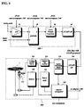
- the audio format converter 30 converts the received audio signal into record-formatted data as soon as the 'conversion start' signal is received, and after detecting the set of the 'START' signal the ATAPI interface 40 continuously checks whether the format-converted data are received and it is possible to transmit (Step 2).
Landscapes
- Engineering & Computer Science (AREA)
- Signal Processing (AREA)
- Multimedia (AREA)
- Signal Processing For Digital Recording And Reproducing (AREA)
Abstract
Description
Claims (17)
- An audio data receiving apparatus, comprising:a selecting means for selecting an audio signal source among a plurality of audio signal sources;a converting means for converting the selected audio signal into record-formatted audio data; anda connecting means for transferring the record-formatted audio data to a disk recording/reproducing device without passing through the preparation steps for transferring data when a record is requested through the disk recording/reproducing device, wherein the preparation steps are specified in the bus standard adopted in a personal computer.
- An apparatus set forth in claim 1, wherein said bus standard is the AT Attached Packet Interface (ATAPI) protocol.
- An apparatus set forth in claim 1 or 2, further comprising a sampling means for converting an analog signal into digital data by sampling the analog signal.
- An apparatus set forth in any of claims 1 to 3, wherein said connecting means comprises:a serial-to-parallel converting means for converting the record-formatted serial data into 8-bit parallel data and outputting them together with a data writing pulse;a memory control means for storing the converted parallel data in a memory sequentially whenever the data writing pulse is applied, and for retrieving the stored data into 16-bit parallel data sequentially and generating a transfer-ready signal at the same time when the storing of audio data is completed; anda transmitting means for transmitting the 16-bit parallel data to the disk recording/reproducing device through the bus when the transfer-ready signal is applied.
- An audio data recording apparatus, comprising:a connecting means for sending/receiving signals through a bus in accordance with a bus protocol compatible with a bus protocol adopted in a personal computer;a recording means for modulating audio data received through said connecting means into recording signals and recording the modulated signals in a recording medium; anda controlling means for controlling said connecting means to transmit a 'transfer start' signal to a counter part of the bus without sending/receiving packet commands through the bus when a record command is received.
- An apparatus set forth in claim 5, wherein said bus protocol adopted in a personal computer is the AT Attached Packet Interface (ATAPI) protocol.
- An apparatus set forth in claim 5 or 6, wherein said controlling means changes the binary level of the 'transfer start' signal for the counter part to start data transfer.
- An apparatus set forth in claim 7, wherein said controlling means restores the binary level of the 'transfer start' signal when a record stop is requested.
- A method for sending/receiving audio data through a bus, comprising the steps of:(a) entering into data communication mode without passing through preparation steps for transferring data when a record is requested, wherein the preparation steps includes occupying the bus and communication standby mode which require issuing necessary packet commands and executing them.(b) sending/receiving audio data in the data communication mode;(c) escaping the data communication mode when a recording stop is requested; and(d) interrupting data transferring operation.
- A method set forth in claim 9, wherein in said step (a), a receiving part transmits a 'transfer start' signal to a transmitting part without passing through the preparation steps for transferring data when a record is requested.
- A method set forth in claim 10, wherein the receiving part changes the state of the 'transfer start' signal for the transmitting part to start data transfer.
- A method set forth in claim 11, wherein said step (C) restores the state of the transfer start signal.
- A method set forth in any of claims 9 to 11, wherein the packet commands are specified in the AT Attached Packet Interface (ATAPI) protocol.
- A method set forth in claim 9 or 13, wherein said step (a) transmits a 'transfer start' signal and a command requesting start of format conversion of a received audio signal at the same time.
- A method for sending/receiving data between two devices through a bus, comprising the steps of:(a) transmitting a 'transfer start' signal through the bus and a 'conversion start' signal to a transmitting device at the same time without passing through preparation steps for transferring data when a record is requested to a receiving device, wherein the preparation steps includes occupying the bus and entering into communication standby mode which require issuing necessary packet commands and executing them;(b) converting an input signal into data streams of the pre-determined format when the transmitting device receives the 'conversion start' signal;(c) checking whether the 'transfer start' signal is received when the converted data is received, and transmitting the converted data to the receiving device through the bus based upon the checked result; and(d) receiving the transmitted data through the bus and recording the received data in a recording medium.
- A method set forth in claim 15, wherein the bus is compatible with the AT Attached Packet Interface (ATAPI) bus.
- A method set forth in claim 15 or 16, wherein said step (a) transmits the 'conversion start' signal to the transmitting device through other signal path different from the bus.
Applications Claiming Priority (2)
| Application Number | Priority Date | Filing Date | Title |
|---|---|---|---|
| KR9928377 | 1999-07-14 | ||
| KR1019990028377A KR100575538B1 (en) | 1999-07-14 | 1999-07-14 | Audio data converter and data transmission method therefrom |
Publications (3)
| Publication Number | Publication Date |
|---|---|
| EP1069565A2 true EP1069565A2 (en) | 2001-01-17 |
| EP1069565A3 EP1069565A3 (en) | 2004-08-18 |
| EP1069565B1 EP1069565B1 (en) | 2007-09-19 |
Family
ID=19601571
Family Applications (1)
| Application Number | Title | Priority Date | Filing Date |
|---|---|---|---|
| EP00114048A Expired - Lifetime EP1069565B1 (en) | 1999-07-14 | 2000-07-05 | An audio data recording apparatus and audio data sending/receiving method of the apparatus |
Country Status (4)
| Country | Link |
|---|---|
| US (1) | US6868463B1 (en) |
| EP (1) | EP1069565B1 (en) |
| KR (1) | KR100575538B1 (en) |
| DE (1) | DE60036438T2 (en) |
Families Citing this family (11)
| Publication number | Priority date | Publication date | Assignee | Title |
|---|---|---|---|---|
| JP3797104B2 (en) * | 2000-12-28 | 2006-07-12 | ヤマハ株式会社 | Digital audio signal recording device |
| CA2343437A1 (en) * | 2001-04-06 | 2002-10-06 | Ibm Canada Limited-Ibm Canada Limitee | Method and system for cross platform, parallel processing |
| KR100389868B1 (en) * | 2001-07-21 | 2003-07-04 | 삼성전자주식회사 | A complex system of television plus optical recording/reproduction unit and design method of the complex system |
| US20030081932A1 (en) * | 2001-10-25 | 2003-05-01 | Hanes David H. | Computer-readable medium and method for providing a generic interface to a CD-recorder device |
| TWI329312B (en) * | 2002-05-21 | 2010-08-21 | Ind Tech Res Inst | |
| JP2004134870A (en) * | 2002-10-08 | 2004-04-30 | Kakushi Mizuguchi | Adaptor for telephone recording |
| JP2006012392A (en) * | 2004-05-24 | 2006-01-12 | Fujitsu Ten Ltd | Information reproducing / recording apparatus and information transfer module |
| KR100690131B1 (en) * | 2004-12-03 | 2007-03-08 | 엘지전자 주식회사 | How to adjust the playback audio output level |
| JP2006191171A (en) * | 2004-12-28 | 2006-07-20 | Canon Inc | Control device, control method and program |
| JP2012108254A (en) * | 2010-11-16 | 2012-06-07 | Toshiba Corp | Audio format conversion apparatus and audio format conversion method |
| CN118819458B (en) * | 2024-09-20 | 2024-12-13 | 深圳深蕾科技股份有限公司 | Universal transmission interface implementation method for audio data, audio equipment and storage medium |
Family Cites Families (14)
| Publication number | Priority date | Publication date | Assignee | Title |
|---|---|---|---|---|
| CA1243774A (en) * | 1983-06-15 | 1988-10-25 | Takaharu Noguchi | Pcm signal recording/reproducing apparatus |
| US5041921A (en) * | 1987-01-06 | 1991-08-20 | Duplitronics, Inc. | System for recording custom albums from a library of pre-recorded items |
| US5953513A (en) * | 1992-07-09 | 1999-09-14 | Hitachi, Ltd. | Recording and reproducing device for recording and reproducing information from different kinds of storage media having different sector formats |
| US5365467A (en) * | 1992-12-25 | 1994-11-15 | Yamaha Corporation | Signal processor for providing variable acoustic effect |
| US5999505A (en) * | 1993-03-26 | 1999-12-07 | Sony Corporation | Information processing device for continuously and discontinuously processing recorded data and recording medium therefor |
| CA2169131C (en) * | 1995-02-28 | 2004-08-10 | Fabrizio Caffarelli | Compact disc recording system and method |
| KR980013417A (en) * | 1996-07-18 | 1998-04-30 | 구자홍 | Method and apparatus for transmitting audio data |
| JPH10106172A (en) | 1996-09-30 | 1998-04-24 | Sony Corp | Data recording / reproducing device |
| US6078966A (en) * | 1997-01-14 | 2000-06-20 | Mitsumi Electric Co., Ltd. | Switching means for directly controlling operation of data storage devices, data storage/reproducing devices, and data reproducing devices |
| TW344059B (en) * | 1997-06-14 | 1998-11-01 | Winbond Electronics Corp | Method and device for carrying out updating firmware of CD-ROM driver through ATA/IDE interface |
| KR100271443B1 (en) * | 1997-06-30 | 2000-11-15 | 전주범 | Audio editor of a dvcr |
| JPH11312143A (en) * | 1998-04-28 | 1999-11-09 | Clarion Co Ltd | Information processor, its method, car audio system, its control method, and recording medium with information processing program recorded therein |
| TW394887B (en) * | 1998-05-14 | 2000-06-21 | Mustek Systems Inc | ATAPI interface control circuit and DVD player for this interfere control circuit |
| KR100546578B1 (en) * | 1998-11-26 | 2006-04-14 | 엘지전자 주식회사 | Apparatus For Converting Digital Audio Data Format |
-
1999
- 1999-07-14 KR KR1019990028377A patent/KR100575538B1/en not_active Expired - Fee Related
-
2000
- 2000-07-05 DE DE60036438T patent/DE60036438T2/en not_active Expired - Lifetime
- 2000-07-05 EP EP00114048A patent/EP1069565B1/en not_active Expired - Lifetime
- 2000-07-14 US US09/617,049 patent/US6868463B1/en not_active Expired - Fee Related
Also Published As
| Publication number | Publication date |
|---|---|
| KR100575538B1 (en) | 2006-05-03 |
| EP1069565A3 (en) | 2004-08-18 |
| DE60036438T2 (en) | 2008-06-19 |
| KR20010009790A (en) | 2001-02-05 |
| DE60036438D1 (en) | 2007-10-31 |
| EP1069565B1 (en) | 2007-09-19 |
| US6868463B1 (en) | 2005-03-15 |
Similar Documents
| Publication | Publication Date | Title |
|---|---|---|
| US4802152A (en) | Compact disc drive apparatus having an interface for transferring data and commands to and from a host controller | |
| KR940008691B1 (en) | Data recording and reproducing method | |
| EP1069565B1 (en) | An audio data recording apparatus and audio data sending/receiving method of the apparatus | |
| EP0689208A1 (en) | Method for block oriented addressing | |
| CN100416526C (en) | Optical storage system including interface for transmitting data | |
| KR19980033330A (en) | Information recording method and system | |
| US5359583A (en) | Method for preventing erroneous recording in compact disc player | |
| JPH10149627A (en) | Optical disk recorder | |
| EP0813141A2 (en) | A recordable compact disk controller circuit | |
| KR20010107509A (en) | A management method for reproducing error and a disk drive making use of the management method | |
| JPH02132514A (en) | drive interface | |
| JPH05265939A (en) | Data transfer equipment | |
| US6975567B2 (en) | Method and apparatus for copying/moving data on optical recording medium | |
| US6311014B1 (en) | Unified audio/video interface for a digital video disk system | |
| US20020172115A1 (en) | Disk drive device | |
| JP2926636B2 (en) | Interface method and apparatus in digital signal processing system | |
| JP2001184780A (en) | Recording control method for recording equipment | |
| KR100228670B1 (en) | Efficient memory managing device of optical disc reproduction system | |
| US20050174914A1 (en) | Recording/reproducing apparatus | |
| US6470063B2 (en) | Method and device to update data transfer count for disc drive | |
| KR100973165B1 (en) | How to measure recording speed of optical disc drive | |
| JP2557351B2 (en) | Disc playback device | |
| US20020076200A1 (en) | Host system, driving apparatus, information recording and reading method for the host system, and information recording and reading method for the driving apparatus | |
| KR100224684B1 (en) | Atapi interface apparatus for processing complementary data and interrupt for digital video disk | |
| US20030167435A1 (en) | Encoding method for an optical recorder |
Legal Events
| Date | Code | Title | Description |
|---|---|---|---|
| PUAI | Public reference made under article 153(3) epc to a published international application that has entered the european phase |
Free format text: ORIGINAL CODE: 0009012 |
|
| AK | Designated contracting states |
Kind code of ref document: A2 Designated state(s): AT BE CH CY DE DK ES FI FR GB GR IE IT LI LU MC NL PT SE |
|
| AX | Request for extension of the european patent |
Free format text: AL;LT;LV;MK;RO;SI |
|
| RIN1 | Information on inventor provided before grant (corrected) |
Inventor name: BAIK, SEUNG II Inventor name: JUNG, WON GEUN C/O LG ELEC. INC./PATENT GROUP |
|
| RIN1 | Information on inventor provided before grant (corrected) |
Inventor name: BAIK, SEUNG II Inventor name: JUNG, WON GEUN C/O LG ELEC. INC./PATENT GROUP |
|
| PUAL | Search report despatched |
Free format text: ORIGINAL CODE: 0009013 |
|
| AK | Designated contracting states |
Kind code of ref document: A3 Designated state(s): AT BE CH CY DE DK ES FI FR GB GR IE IT LI LU MC NL PT SE |
|
| AX | Request for extension of the european patent |
Extension state: AL LT LV MK RO SI |
|
| 17P | Request for examination filed |
Effective date: 20050217 |
|
| AKX | Designation fees paid |
Designated state(s): DE FR GB NL |
|
| 17Q | First examination report despatched |
Effective date: 20050415 |
|
| RBV | Designated contracting states (corrected) |
Designated state(s): DE FR GB NL |
|
| GRAP | Despatch of communication of intention to grant a patent |
Free format text: ORIGINAL CODE: EPIDOSNIGR1 |
|
| GRAS | Grant fee paid |
Free format text: ORIGINAL CODE: EPIDOSNIGR3 |
|
| GRAA | (expected) grant |
Free format text: ORIGINAL CODE: 0009210 |
|
| AK | Designated contracting states |
Kind code of ref document: B1 Designated state(s): DE FR GB NL |
|
| REG | Reference to a national code |
Ref country code: GB Ref legal event code: FG4D |
|
| REF | Corresponds to: |
Ref document number: 60036438 Country of ref document: DE Date of ref document: 20071031 Kind code of ref document: P |
|
| ET | Fr: translation filed | ||
| PLBE | No opposition filed within time limit |
Free format text: ORIGINAL CODE: 0009261 |
|
| STAA | Information on the status of an ep patent application or granted ep patent |
Free format text: STATUS: NO OPPOSITION FILED WITHIN TIME LIMIT |
|
| 26N | No opposition filed |
Effective date: 20080620 |
|
| REG | Reference to a national code |
Ref country code: FR Ref legal event code: PLFP Year of fee payment: 16 |
|
| PGFP | Annual fee paid to national office [announced via postgrant information from national office to epo] |
Ref country code: GB Payment date: 20150615 Year of fee payment: 16 |
|
| PGFP | Annual fee paid to national office [announced via postgrant information from national office to epo] |
Ref country code: FR Payment date: 20150612 Year of fee payment: 16 Ref country code: NL Payment date: 20150612 Year of fee payment: 16 |
|
| PGFP | Annual fee paid to national office [announced via postgrant information from national office to epo] |
Ref country code: DE Payment date: 20150612 Year of fee payment: 16 |
|
| REG | Reference to a national code |
Ref country code: DE Ref legal event code: R119 Ref document number: 60036438 Country of ref document: DE |
|
| REG | Reference to a national code |
Ref country code: NL Ref legal event code: MM Effective date: 20160801 |
|
| GBPC | Gb: european patent ceased through non-payment of renewal fee |
Effective date: 20160705 |
|
| PG25 | Lapsed in a contracting state [announced via postgrant information from national office to epo] |
Ref country code: DE Free format text: LAPSE BECAUSE OF NON-PAYMENT OF DUE FEES Effective date: 20170201 Ref country code: FR Free format text: LAPSE BECAUSE OF NON-PAYMENT OF DUE FEES Effective date: 20160801 Ref country code: NL Free format text: LAPSE BECAUSE OF NON-PAYMENT OF DUE FEES Effective date: 20160801 |
|
| REG | Reference to a national code |
Ref country code: FR Ref legal event code: ST Effective date: 20170331 |
|
| PG25 | Lapsed in a contracting state [announced via postgrant information from national office to epo] |
Ref country code: GB Free format text: LAPSE BECAUSE OF NON-PAYMENT OF DUE FEES Effective date: 20160705 |