EP1069481B1 - Photosensitive drum unit and a ground plate used therewith - Google Patents
Photosensitive drum unit and a ground plate used therewith Download PDFInfo
- Publication number
- EP1069481B1 EP1069481B1 EP00122547A EP00122547A EP1069481B1 EP 1069481 B1 EP1069481 B1 EP 1069481B1 EP 00122547 A EP00122547 A EP 00122547A EP 00122547 A EP00122547 A EP 00122547A EP 1069481 B1 EP1069481 B1 EP 1069481B1
- Authority
- EP
- European Patent Office
- Prior art keywords
- photosensitive drum
- ground plate
- projections
- drum unit
- tubular member
- Prior art date
- Legal status (The legal status is an assumption and is not a legal conclusion. Google has not performed a legal analysis and makes no representation as to the accuracy of the status listed.)
- Expired - Lifetime
Links
Images

Classifications
-
- G—PHYSICS
- G03—PHOTOGRAPHY; CINEMATOGRAPHY; ANALOGOUS TECHNIQUES USING WAVES OTHER THAN OPTICAL WAVES; ELECTROGRAPHY; HOLOGRAPHY
- G03G—ELECTROGRAPHY; ELECTROPHOTOGRAPHY; MAGNETOGRAPHY
- G03G15/00—Apparatus for electrographic processes using a charge pattern
-
- G—PHYSICS
- G03—PHOTOGRAPHY; CINEMATOGRAPHY; ANALOGOUS TECHNIQUES USING WAVES OTHER THAN OPTICAL WAVES; ELECTROGRAPHY; HOLOGRAPHY
- G03G—ELECTROGRAPHY; ELECTROPHOTOGRAPHY; MAGNETOGRAPHY
- G03G15/00—Apparatus for electrographic processes using a charge pattern
- G03G15/75—Details relating to xerographic drum, band or plate, e.g. replacing, testing
- G03G15/751—Details relating to xerographic drum, band or plate, e.g. replacing, testing relating to drum
Definitions
- the present invention relates to a drum unit and a ground plate for image forming devices such as copying machines, facsimile devices or laser printers.
- an image from an original document is optically read by an exposure unit, and an electrostatic latent image is formed on a photosensitive drum.
- a developing device is disposed adjacent to the photosensitive drum for forming a toner image thereon.
- the developing device includes a toner hopper, and toner supplied from the hopper is given an electric charge opposite that of the electrostatic latent image formed on the photosensitive drum. The toner adheres to the surface of the photosensitive drum to form a toner-developed image.
- the photosensitive drum includes a tubular member formed from an electroconductive metal, and two flange members which are pressed into the openings defined on the opposite ends of the tubular member.
- An aperture is defined in the central portion of each of the flange members, and a support axle passes through the two apertures for supporting the drum unit in the copying machine.
- a ground plate is attached to the flange member, with a portion of the outer circumference thereof in contact with a portion of the inner circumferential surface of the tubular member and the inner circumference thereof in contact with the support axle.
- a substance for corrosion prevention such as aluminum oxide
- portions of the ground plate have a diameter which are larger than the inner diameter of the tubular member.
- the ground plate is then forced into the tubular member, thereby deforming portions of the outer circumference of the ground plate so that it may fit into the tubular member. This action scratches the inner circumferential surface of the tubular member, and removes enough of the coating so that electricity may be conducted between the tubular member and the ground plate.
- the tubular member can be deformed when the ground plate is forced into the tubular member. If the tubular member is deformed in such a manner, it may produce unsatisfactory copies. In addition, the tubular member is often made thinner in order to reduce the total weight of the copying machine, as well as its cost of production. However, the amount of deformation that occurs during ground plate installation often increases when the thickness of the tubular member is reduced.
- JP 05072955 discloses a ground plate for use in a photocopier drum for electrical grounding.
- the design of the plate incorporates several pointed projections for making a good electrical contact with the drum. These projections are surrounded by cutaways which allow the projections to be more readily bent upon insertion of the ground plate into the drum.
- the design presented in this document does not disclose the provision of two large cutaways on opposite sides of the plate. These large cutaways allow the ground plate to elastically deform upon insertion, which both reduces the damage to the drum and further improves the electrical connection.
- a photosensitive drum unit for an image reproducing device includes a tubular member having at least one opening at one end thereof, the tubular member having an inner diameter D. At least one flange member is connectable with the opening of the tubular member, and at least one ground plate is connectable with the flange member.
- the ground plate has a diameter d, and includes a disc-shaped substrate having a diameter d' smaller than said inner diameter D of said tubular member. At least one projection extends beyond an outer circumference of the disc-shaped substrate, and two cutaways are formed in the disc-shaped substrate on either side of the projection, to improve flexibility.
- the diameter d of the ground plate is larger than the diameter D of the tubular member.
- an outer circumferential surface of the flange member includes a bevelled portion, which is adjacent to the projection when the ground plate and the flange member are connected to each other.
- the ground plate includes a plurality of the projections.
- the ground plate is composed of stainless steel.
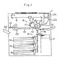
- FIG. 1 A cross-sectional view of the copying machine incorporating the present invention in accordance with one embodiment thereof is depicted in Fig. 1. It should be noted, however, that this invention can be applied equally as well to laser printers and facsimile devices
- the copying machine 1 includes an optical exposure system 5 for obtaining an image from an original document.
- the optical exposure system 5 includes a light source, mirrors and a lens unit.
- an image processor 6 Located in the central portion of the copying machine 1 is an image processor 6 for forming a toner image of the original document on a blank sheet of paper.
- the image processor 6 includes a photosensitive drum 7, on the outer circumference of which an electrostatic latent image is formed.
- a charging device 8 for charging the photosensitive drum 7 with a predetermined level of electric charge
- a developing device 9 for developing the electrostatic latent image
- a transfer-separation device 10 for transferring a toner image to a sheet of paper and detaching the sheet from the photosensitive drum 7, and a cleaning device 11 for removing excess toner from the photosensitive drum 7.
- a paper supply unit 12 is located in the lower portion of the copying machine 1.
- the paper supply unit 12 includes a bypass table 13, three paper supply cassettes 14, 15 and 16 arranged perpendicular to the lower portion of the copying machine 1, an oversized paper supply cassette 17, and a paper transporting device 18 for transporting the sheets stored in the bypass table 13 or paper supply cassettes 14-17 to the image processor 6.
- Disposed in a portion of the sheet-transport stream forward of the image processor 6 are a paper discharge belt 19 for transferring the sheet toward the left side of the copying machine 1 in Fig. 1, a fixing device 20 for fusing and fixing toner images onto the sheet, a discharging roller 21 for discharging the sheet, and a sheet tray 22 for receiving the sheet.
- a toner hopper 23 for supplying toner to the image processor 6 is attached to the developing device 9.
- a toner cartridge 24 is detachably connected to the toner hopper 23.
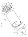
- the photosensitive drum unit 7 includes a tubular member 31 and two flange members 32.
- the tubular member 31 is composed of an electroconductive metal substrate (such as aluminum or stainless steel), and an organic or non-organic photoconductor layer formed on the outer circumferential surface thereof.
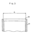
- the tubular member 31 includes two end portions (openings) 33, with each end portion 33 including a flange fitting portion 34.
- Each flange member 32 is composed of ABS resin and is generally disc-shaped, and is sized so that the diameter thereof is generally the same as the inner diameter D of the tubular member 31 (as shown in Fig. 3). As shown in Figs. 2, 4, and 5, the inner side of each flange member 32 include seven first projections 36, with the first projection 36 located in the center portion of each flange member 32 provided with an aperture 35 which engages with a support axle (not shown). The outer circumferential surface of each flange member 32 constitutes a contact portion 46 which is inserted into the opening 33 of the tubular member 31. A bevelled portion 47 is formed on the inner side of each flange member 32.
- a ground plate 37 is formed of stainless steel or copper, and is attached to the inner surface of one or both flange members 32.
- the ground plate 37 includes a disc-shaped substrate 38, which has a diameter d' smaller than the inner diameter D of the tubular member 31.
- the ground plate 37 further includes five attachment holes 40 and two cutaways 41, which correspond to the first projections 36 on each flange member 32.
- Each attachment hole 40 is provided with three second projections 45, which point inward toward the center thereof.
- the ground plate 37 is also provided with six third projections 42, which extend beyond the outer periphery of the disc-shaped substrate 38.
- the diameter d of each ground plate 37 is measured from the tips of opposing third projections 42, and is greater than the inner diameter D of the tubular member 31.
- Two cutaways 43 are formed on either side of each of the third projections 42. The presence of these cutaways 43 increase the elastic deformability of the third projections 42 relative to the disc-shaped substrate 38, as well as reducing the amount of pressure needed in push the flange member 32 into the tubular member 31.
- the ground plate 37 is attached to the inner surface of the flange member 32 by fitting the first projections 36 into the attachment holes 40. When this occurs, the second projections 45 engage with the first projections 36, thereby securely fixing the ground plate 37 to the inner surface of the flange member 32.
- One of the cutaways 41 on the ground plate 37 includes a turn-back portion 48. After the ground plate 37 is attached to the flange member 32, the turn-back portion is bent backward and over a portion of the central attachment hole 44.
- the flange member 32 and ground plate 37 are then forced into the opening 33 of the tubular member 31.
- the third projections 42 are elastically deformed, and scratch the inner surface of the tubular member 31.
- the protective layer formed on the inner surface of the tubular member 31 is removed, thereby creating an electrical connection between the ground plate 37 and the tubular member 31, as well as helping secure the flange member 32 in the opening 33.
- the bevelled portion 47 on the flange member 32 serves to provide space for the deformed third projections 42 .
- each of the apertures 35 are engaged with the support axles (not shown) provided in the copying machine.
- the support axles When the support axles are inserted into the apertures 35, one end of each of the support axles are in contact with the turn-back portion 48 provided on each of the ground plates 37, thereby creating an electrical connection between the ground plates 37 and the support axles.
- Table 1 shows the results of a series of experiments, in which the thickness and the diameter d of the ground plate 37 was varied in order to find a ground plate that would create an optimal electrical connection with the tubular member 31, without deforming the tubular member 31 during installation.
- the overall evaluation given to each embodiment was based on the amount of deformation in the tubular member 31, the quality and quantity of electrical conduction between the tubular member 31 and the ground plate 37, the number of third projections bent after installation of the ground plate 37 into the tubular member 31, and the number of scratches in the inner surface of the tubular member 31.
- the thickness of the tubular member 31 in this experiment was 0.8 mm.
- Table 2 shows the results of a series of experiments similar to those in Table 1, except that the overall evaluation given to each embodiment was based only on the amount of deformation to the tubular member 31 and the quantity and quality of the electrical conduction between the tubular member 31 and the ground plate 37.
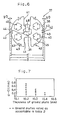
- Fig. 7 shows a graphical representation of the embodiments in Table 2 which received an "acceptable” rating.
Landscapes
- Physics & Mathematics (AREA)
- General Physics & Mathematics (AREA)
- Discharging, Photosensitive Material Shape In Electrophotography (AREA)
- Electrophotography Configuration And Component (AREA)
- Photoreceptors In Electrophotography (AREA)
Description
- The present invention relates to a drum unit and a ground plate for image forming devices such as copying machines, facsimile devices or laser printers.
- In an image forming device such as a copying machine, an image from an original document is optically read by an exposure unit, and an electrostatic latent image is formed on a photosensitive drum. A developing device is disposed adjacent to the photosensitive drum for forming a toner image thereon. The developing device includes a toner hopper, and toner supplied from the hopper is given an electric charge opposite that of the electrostatic latent image formed on the photosensitive drum. The toner adheres to the surface of the photosensitive drum to form a toner-developed image.
- The photosensitive drum includes a tubular member formed from an electroconductive metal, and two flange members which are pressed into the openings defined on the opposite ends of the tubular member. An aperture is defined in the central portion of each of the flange members, and a support axle passes through the two apertures for supporting the drum unit in the copying machine.
- In order for electricity to flow between the surface of the tubular member and the body of the copying machine, a ground plate is attached to the flange member, with a portion of the outer circumference thereof in contact with a portion of the inner circumferential surface of the tubular member and the inner circumference thereof in contact with the support axle. However, because the inner surface of the tubular member is often coated with a substance for corrosion prevention (such as aluminum oxide), this coating must be removed so that electricity can be conducted between the tubular member and the ground plate.
- In order to do this, portions of the ground plate have a diameter which are larger than the inner diameter of the tubular member. The ground plate is then forced into the tubular member, thereby deforming portions of the outer circumference of the ground plate so that it may fit into the tubular member. This action scratches the inner circumferential surface of the tubular member, and removes enough of the coating so that electricity may be conducted between the tubular member and the ground plate.
- However, due to the configuration of the ground plate, the tubular member can be deformed when the ground plate is forced into the tubular member. If the tubular member is deformed in such a manner, it may produce unsatisfactory copies. In addition, the tubular member is often made thinner in order to reduce the total weight of the copying machine, as well as its cost of production. However, the amount of deformation that occurs during ground plate installation often increases when the thickness of the tubular member is reduced.
- JP 05072955 discloses a ground plate for use in a photocopier drum for electrical grounding. The design of the plate, incorporates several pointed projections for making a good electrical contact with the drum. These projections are surrounded by cutaways which allow the projections to be more readily bent upon insertion of the ground plate into the drum. The design presented in this document, however, does not disclose the provision of two large cutaways on opposite sides of the plate. These large cutaways allow the ground plate to elastically deform upon insertion, which both reduces the damage to the drum and further improves the electrical connection.
- It is therefore an object of the present invention to provide a photosensitive drum unit in an image producing device in which electricity can be reliably conducted between the photosensitive drum unit and the body of the image producing device without deforming the tubular member during ground plate installation.
- According to one aspect of the present invention, a photosensitive drum unit for an image reproducing device includes a tubular member having at least one opening at one end thereof, the tubular member having an inner diameter D. At least one flange member is connectable with the opening of the tubular member, and at least one ground plate is connectable with the flange member. The ground plate has a diameter d, and includes a disc-shaped substrate having a diameter d' smaller than said inner diameter D of said tubular member. At least one projection extends beyond an outer circumference of the disc-shaped substrate, and two cutaways are formed in the disc-shaped substrate on either side of the projection, to improve flexibility. The diameter d of the ground plate is larger than the diameter D of the tubular member.
- According to another embodiment of the present invention, an outer circumferential surface of the flange member includes a bevelled portion, which is adjacent to the projection when the ground plate and the flange member are connected to each other.
- According to another embodiment of the present invention, the ground plate includes a plurality of the projections.
- According to yet another embodiment of the present invention, the ground plate is composed of stainless steel.
- These and other objects, features, aspects and advantages of the present invention will become more fully apparent from the following detailed description of the present invention when taken in conjunction with the accompanying drawings, where like reference numerals denote corresponding parts throughout.
-
- Fig. 1 is a side schematic view of a copying machine, which includes a photosensitive drum in accordance with one embodiment of the present invention;
- Fig. 2 is an exploded oblique view of a photosensitive drum unit, showing one embodiment of the present invention;
- Fig. 3 is a fragmentary cross-sectional view of the tubular member depicted in Fig. 2;
- Fig. 4 is a frontal view of the flange member depicted in Fig. 2;
- Fig. 5 is a side cross-sectional view of the flange member depicted in Fig. 4;
- Fig. 6 is a frontal view of the ground plate depicted in Fig. 2;
- Fig. 7 is a chart showing the relationship between the thickness of the ground plate and the difference in diameters of the tubular member and the ground plate.
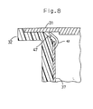
- Fig. 8 is a fragmentary cross-sectional view of the flange member, the tubular member and the ground plate, showing their relative configurations when properly installed.
-
- A cross-sectional view of the copying machine incorporating the present invention in accordance with one embodiment thereof is depicted in Fig. 1. It should be noted, however, that this invention can be applied equally as well to laser printers and facsimile devices
- The copying machine 1 includes an
optical exposure system 5 for obtaining an image from an original document. Theoptical exposure system 5 includes a light source, mirrors and a lens unit. Located in the central portion of the copying machine 1 is animage processor 6 for forming a toner image of the original document on a blank sheet of paper. Theimage processor 6 includes a photosensitive drum 7, on the outer circumference of which an electrostatic latent image is formed. Surrounding the photosensitive drum 7, there is acharging device 8 for charging the photosensitive drum 7 with a predetermined level of electric charge, a developing device 9 for developing the electrostatic latent image, a transfer-separation device 10 for transferring a toner image to a sheet of paper and detaching the sheet from the photosensitive drum 7, and acleaning device 11 for removing excess toner from the photosensitive drum 7. - A paper supply unit 12 is located in the lower portion of the copying machine 1. The paper supply unit 12 includes a bypass table 13, three
paper supply cassettes paper supply cassette 17, and apaper transporting device 18 for transporting the sheets stored in the bypass table 13 or paper supply cassettes 14-17 to theimage processor 6. Disposed in a portion of the sheet-transport stream forward of theimage processor 6 are apaper discharge belt 19 for transferring the sheet toward the left side of the copying machine 1 in Fig. 1, afixing device 20 for fusing and fixing toner images onto the sheet, adischarging roller 21 for discharging the sheet, and asheet tray 22 for receiving the sheet. - A toner hopper 23 for supplying toner to the
image processor 6 is attached to the developing device 9. Atoner cartridge 24 is detachably connected to thetoner hopper 23. - As shown in Fig. 2, the photosensitive drum unit 7 includes a
tubular member 31 and twoflange members 32. Thetubular member 31 is composed of an electroconductive metal substrate (such as aluminum or stainless steel), and an organic or non-organic photoconductor layer formed on the outer circumferential surface thereof. - The
tubular member 31 includes two end portions (openings) 33, with eachend portion 33 including aflange fitting portion 34. - Each
flange member 32 is composed of ABS resin and is generally disc-shaped, and is sized so that the diameter thereof is generally the same as the inner diameter D of the tubular member 31 (as shown in Fig. 3). As shown in Figs. 2, 4, and 5, the inner side of eachflange member 32 include sevenfirst projections 36, with thefirst projection 36 located in the center portion of eachflange member 32 provided with anaperture 35 which engages with a support axle (not shown). The outer circumferential surface of eachflange member 32 constitutes acontact portion 46 which is inserted into the opening 33 of thetubular member 31. Abevelled portion 47 is formed on the inner side of eachflange member 32. - Referring now to Fig. 6, a
ground plate 37 is formed of stainless steel or copper, and is attached to the inner surface of one or bothflange members 32. Theground plate 37 includes a disc-shaped substrate 38, which has a diameter d' smaller than the inner diameter D of thetubular member 31. Theground plate 37 further includes fiveattachment holes 40 and twocutaways 41, which correspond to thefirst projections 36 on eachflange member 32. Eachattachment hole 40 is provided with threesecond projections 45, which point inward toward the center thereof. - The
ground plate 37 is also provided with sixthird projections 42, which extend beyond the outer periphery of the disc-shapedsubstrate 38. The diameter d of eachground plate 37 is measured from the tips of opposingthird projections 42, and is greater than the inner diameter D of thetubular member 31. Twocutaways 43 are formed on either side of each of thethird projections 42. The presence of thesecutaways 43 increase the elastic deformability of thethird projections 42 relative to the disc-shapedsubstrate 38, as well as reducing the amount of pressure needed in push theflange member 32 into thetubular member 31. - The
ground plate 37 is attached to the inner surface of theflange member 32 by fitting thefirst projections 36 into the attachment holes 40. When this occurs, thesecond projections 45 engage with thefirst projections 36, thereby securely fixing theground plate 37 to the inner surface of theflange member 32. - One of the
cutaways 41 on theground plate 37 includes a turn-back portion 48. After theground plate 37 is attached to theflange member 32, the turn-back portion is bent backward and over a portion of thecentral attachment hole 44. - The
flange member 32 andground plate 37 are then forced into theopening 33 of thetubular member 31. As can be seen in Fig. 8, thethird projections 42 are elastically deformed, and scratch the inner surface of thetubular member 31. As a result, the protective layer formed on the inner surface of thetubular member 31 is removed, thereby creating an electrical connection between theground plate 37 and thetubular member 31, as well as helping secure theflange member 32 in theopening 33. In addition, the bevelledportion 47 on theflange member 32 serves to provide space for the deformedthird projections 42 . - After connecting the
flange members 32 to the opposing ends of thetubular member 31, each of theapertures 35 are engaged with the support axles (not shown) provided in the copying machine. When the support axles are inserted into theapertures 35, one end of each of the support axles are in contact with the turn-back portion 48 provided on each of theground plates 37, thereby creating an electrical connection between theground plates 37 and the support axles. - Table 1 shows the results of a series of experiments, in which the thickness and the diameter d of the
ground plate 37 was varied in order to find a ground plate that would create an optimal electrical connection with thetubular member 31, without deforming thetubular member 31 during installation. The overall evaluation given to each embodiment was based on the amount of deformation in thetubular member 31, the quality and quantity of electrical conduction between thetubular member 31 and theground plate 37, the number of third projections bent after installation of theground plate 37 into thetubular member 31, and the number of scratches in the inner surface of thetubular member 31. The thickness of thetubular member 31 in this experiment was 0.8 mm.Thickness of ground plate d - D Amount of deformation in tubular member Electrical conduction Number of bent projections Number of scratches Overall evaluation 0.1 mm 0.1 mm none none -- -- failure 0.1 mm 0.2 mm none some -- -- failure 0.1 mm 0.3 mm none some -- -- failure 0.2 mm 0.1 mm none great 2-3 2-3 failure 0.2 mm 0.2 mm none great 3-4 3-4 acceptable 0.2 mm 0.3 mm none great 5-6 5-6 best 0.3 mm 0.1 mm none great 1 1 failure 0.3 mm 0.2 mm none great 3-4 3-4 acceptable 0.3 mm 0.3 mm none great 5-6 5-6 good 0.4 mm 0.1 mm none great 0 1-2 failure 0.4 mm 0.2 mm none great 2-3 2-3 failure 0.4 mm 0.3 mm some great 5-6 5-6 failure 0.4 mm 0.5 mm great great 6 6 failure 0.5 mm 0.1 mm great great -- -- failure 0.5 mm 0.2 mm great great -- -- failure 0.5 mm 0.3 mm great great -- -- failure - Table 2 shows the results of a series of experiments similar to those in Table 1, except that the overall evaluation given to each embodiment was based only on the amount of deformation to the
tubular member 31 and the quantity and quality of the electrical conduction between thetubular member 31 and theground plate 37.Thickness of ground plate d - D Amount of deformation in tubular member Electrical conduction Overall Evaluation 0.1 mm 0.1 mm none none failure 0.1 mm 0.2 mm none some failure 0.1 mm 0.3 mm none some failure 0.1 mm 0.4 mm none some failure 0.1 mm 0.5 mm none some failure 0.1 mm 0.6 mm none some failure 0.1 mm 0.7 mm none some failure 0.1 mm 0.8 mm none some failure 0.2 mm 0.1 mm none great acceptable 0.2 mm 0.2 mm none great acceptable 0.2 mm 0.3 mm none great acceptable 0.2 mm 0.4 mm none great acceptable 0.2 mm 0.5 mm none great acceptable 0.2 mm 0.6 mm none great acceptable 0.2 mm 0.7 mm none great acceptable 0.2 mm 0.8 mm none some failure 0.3 mm 0.1 mm none great acceptable 0.3 mm 0.2 mm none great acceptable 0.3 mm 0.3 mm none great acceptable 0.3 mm 0.4 mm none great acceptable 0.3 mm 0.5 mm none some failure 0.3 mm 0.6 mm none none failure 0.3 mm 0.7 mm none none failure 0.3 mm 0.8 mm none none failure 0.4 mm 0.1 mm none great acceptable 0.4 mm 0.2 mm none great acceptable 0.4 mm 0.3 mm some great failure 0.4 mm 0.4 mm great great failure 0.4 mm 0.5 mm great great failure 0.5 mm 0.1 mm great great failure 0.5 mm 0.2 mm great great failure 0.5 mm 0.3 mm great great failure - Fig. 7 shows a graphical representation of the embodiments in Table 2 which received an "acceptable" rating. As can be seen therein, "acceptable" embodiments will satisfy the inequalities 0.2 mm ≦ X ≦ 0.4 mm and 0.1 mm ≦ Y ≦ -2.5X + 1.2 mm, wherein X = the thickness of the ground plate and Y = the difference between inner diameter D of the
tubular member 31 and the diameter d of theground plate 37. - Various details of the invention may be changed without departing from the scope of the claims. Furthermore, the foregoing description of the embodiments according to the present invention is provided for the purpose of illustration only, and not for the purpose of limiting the invention as defined by the appended claims.
Claims (14)
- A photosensitive drum unit for an image reproducing device, comprising:characterized by:a tubular member (31) having at least one opening (33) at one end thereof, said tubular member (31) having an inner diameter D,at least one flange member (32) connectable with said opening (33) of said tubular member (31), anda ground plate (37) having a disc-shaped substrate (38) having a diameter d' smaller than said inner diameter D of said tubular member (31), at least one projection (42) which extends beyond an outer circumference of said disc-shaped substrate (38), said projection (42) defining a diameter d of said ground plate (37);
wherein said diameter d of said ground plate (37) is larger than said diameter D of said tubular member (31);said projection (42) formed with radially extending sides that extend beyond the outer periphery of the disc-shaped substrate (38),said disc-shaped substrate (38) being formed with two cutaways (41) formed on opposite radial sides of said disc-shaped substrate (38) circumferentially spaced apart from said projection (42), said cutaways providing flexibility to said ground plate (37); - The photosensitive drum unit as in Claim 1, wherein at least one of said two cutaways (41) is formed with a turn-back portion (48) which extends towards a central attachment hole (44) of said ground plate (37), said turn-back portion (48) being configured for contact with an axially extending member which is configured to extend through a central aperture (35) in said ground plate (37).
- The photosensitive drum unit as in Claim 2, wherein said flange member (32) is formed with at least two projections (36), said projections (36) extending into said two cutaways (41).
- The photosensitive drum unit as in Claim 1, wherein said radially extending sides of said projection (42) are parallel to one another.
- The photosensitive drum unit as in Claim 4, wherein said projections (42) is further formed with a pointed tip at an end of said radially extending sides.
- The photosensitive drum unit as in Claim 1, wherein a plurality of said projections (42) are formed on said ground plate (37), each of said projections (42) being circumferentially spaced apart from one another.
- The photosensitive drum unit as in Claim 6, wherein pairs of second cutaways (43) are formed in said disc-shaped substrate (38) on opposing circumferential sides of each of said projections (42).
- The photosensitive drum unit of Claim 1, comprising:one flange member (32);at least two projections, each of said projections (42) extending radially outward from said disc-shaped substrate (38) beyond an outer circumference of said disc-shaped substrate.
- The photosensitive drum unit as in Claim 8, wherein at least one of said two cutaways (41) is formed with a turn-back portion (48) which extends toward a central attachment hole (44) of said ground plate (37), said turn-back portion (48) being configured for contact with an axially extending member which is configured to extend through a central aperture (35) in said ground plate (37).
- The photosensitive drum unit as in Claim 9, wherein said flange member (32) is formed with at least two projections (36), said projections (36) extending into said two cutaways (41).
- The photosensitive drum unit as in Claim 8, wherein said radially extending sides of said projections (42) are parallel to one another.
- The photosensitive drum unit as in Claim 11, wherein said projection (42) is further formed with a pointed tip at an end of said radially extending sides.
- The photosensitive drum unit as in Claim 8, wherein pairs of second cutaways (43) are formed in said disc-shaped substrate (38) on opposing circumferential sides of each of said projections (42).
- The photosensitive drum unit as in Claim 13, wherein a plurality of said projections (42) are formed on said ground plate (37), each of said projections (42) being circumferentially spaced apart from one another.
Applications Claiming Priority (3)
| Application Number | Priority Date | Filing Date | Title |
|---|---|---|---|
| JP7302941A JPH09146411A (en) | 1995-11-21 | 1995-11-21 | Drum unit and earth plate used for drum unit |
| JP30294195 | 1995-11-21 | ||
| EP96117695A EP0775944B1 (en) | 1995-11-21 | 1996-11-05 | Photosensitive drum unit and a ground plate used therewith |
Related Parent Applications (1)
| Application Number | Title | Priority Date | Filing Date |
|---|---|---|---|
| EP96117695A Division EP0775944B1 (en) | 1995-11-21 | 1996-11-05 | Photosensitive drum unit and a ground plate used therewith |
Publications (3)
| Publication Number | Publication Date |
|---|---|
| EP1069481A2 EP1069481A2 (en) | 2001-01-17 |
| EP1069481A3 EP1069481A3 (en) | 2001-01-31 |
| EP1069481B1 true EP1069481B1 (en) | 2005-07-06 |
Family
ID=17914988
Family Applications (2)
| Application Number | Title | Priority Date | Filing Date |
|---|---|---|---|
| EP00122547A Expired - Lifetime EP1069481B1 (en) | 1995-11-21 | 1996-11-05 | Photosensitive drum unit and a ground plate used therewith |
| EP96117695A Expired - Lifetime EP0775944B1 (en) | 1995-11-21 | 1996-11-05 | Photosensitive drum unit and a ground plate used therewith |
Family Applications After (1)
| Application Number | Title | Priority Date | Filing Date |
|---|---|---|---|
| EP96117695A Expired - Lifetime EP0775944B1 (en) | 1995-11-21 | 1996-11-05 | Photosensitive drum unit and a ground plate used therewith |
Country Status (6)
| Country | Link |
|---|---|
| US (1) | US5729792A (en) |
| EP (2) | EP1069481B1 (en) |
| JP (1) | JPH09146411A (en) |
| KR (1) | KR970028891A (en) |
| CN (1) | CN1104663C (en) |
| DE (2) | DE69634920T2 (en) |
Families Citing this family (18)
| Publication number | Priority date | Publication date | Assignee | Title |
|---|---|---|---|---|
| GB2319748B (en) * | 1996-11-30 | 2001-04-18 | Xerox Corp | Photoreceptor |
| JP3283786B2 (en) * | 1997-05-23 | 2002-05-20 | 京セラミタ株式会社 | Drum unit and ground plate used for drum unit |
| US5845173A (en) * | 1997-12-19 | 1998-12-01 | Mitsubishi Chemical America, Inc. | Conductive assembly for a drum in an image forming apparatus |
| JPH11249494A (en) | 1998-03-03 | 1999-09-17 | Canon Inc | Drum flange, cylindrical member, process cartridge, electrophotographic image forming apparatus |
| JPH11249495A (en) * | 1998-03-03 | 1999-09-17 | Canon Inc | Ground member, cylindrical member, process cartridge, electrophotographic image forming apparatus |
| JP2000315037A (en) * | 1999-04-28 | 2000-11-14 | Canon Inc | Electrophotographic photosensitive drum, process cartridge, and electrophotographic image forming apparatus |
| US6785489B2 (en) * | 2002-04-11 | 2004-08-31 | Pentax Technologies Corporation | Ground plate for a photosensitive drum assembly |
| US6788909B2 (en) | 2002-05-31 | 2004-09-07 | Mitsubishi Chemical America, Inc. | Coupling arrangement including drum, flange, and connector |
| US6907205B2 (en) * | 2002-05-31 | 2005-06-14 | Mitsubishi Chemical America, Inc. | Coupling arrangement including drum and flange |
| US6771915B2 (en) * | 2002-12-19 | 2004-08-03 | Mitsubishi Chemical America | Coupling arrangement including optical photoconductive drum and grounding plate |
| US7020410B2 (en) * | 2003-11-21 | 2006-03-28 | Mitsubishi Chemical America, Inc. | Grounding plate assembly for a drum in an image forming apparatus |
| US8326179B2 (en) * | 2008-11-28 | 2012-12-04 | Brother Kogyo Kabushiki Kaisha | Tandem type photosensitive unit and image forming apparatus |
| US8380106B2 (en) * | 2010-06-30 | 2013-02-19 | Lexmark International, Inc. | Center-referenced photoconductor bearing plate and assembly for electro-photographic cartridge |
| TWI417688B (en) * | 2011-01-28 | 2013-12-01 | Green Rich Technology Inc | Photosensitive drum of the conductive device |
| TWI414435B (en) * | 2011-01-28 | 2013-11-11 | Green Rich Technology Inc | Photosensitive drum of the conductive device |
| US8818241B2 (en) * | 2011-09-12 | 2014-08-26 | Static Control Components, Inc. | Universal part for use in an image recording apparatus |
| JP6583123B2 (en) * | 2016-04-26 | 2019-10-02 | 京セラドキュメントソリューションズ株式会社 | Photosensitive drum |
| US10185279B1 (en) * | 2017-07-18 | 2019-01-22 | Xerox Corporation | Grounding device with electrically conductive cushion |
Family Cites Families (9)
| Publication number | Priority date | Publication date | Assignee | Title |
|---|---|---|---|---|
| JPH089732Y2 (en) * | 1989-07-11 | 1996-03-21 | 三田工業株式会社 | Photoconductor drum |
| US5128715A (en) * | 1990-03-19 | 1992-07-07 | Fuji Xerox Co., Ltd. | Print cartidge and image forming apparatus employing the same |
| JPH0572955A (en) * | 1991-09-13 | 1993-03-26 | Canon Inc | Image forming device |
| JPH05119682A (en) * | 1991-10-25 | 1993-05-18 | Mita Ind Co Ltd | Photosensitive drum |
| JPH05119681A (en) * | 1991-10-25 | 1993-05-18 | Mita Ind Co Ltd | Photosensitive drum |
| JPH05297782A (en) * | 1992-04-23 | 1993-11-12 | Toshiba Corp | Photosensitive drum device |
| JP2832788B2 (en) * | 1993-01-11 | 1998-12-09 | 三田工業株式会社 | Photoreceptor drum grounding mechanism |
| DE4443764B4 (en) * | 1993-12-08 | 2004-09-30 | Ricoh Co., Ltd. | Arrangement for holding an image carrier |
| JPH086438A (en) * | 1994-06-20 | 1996-01-12 | Ricoh Co Ltd | Flange for electrophotographic photoreceptor |
-
1995
- 1995-11-21 JP JP7302941A patent/JPH09146411A/en active Pending
-
1996
- 1996-10-25 US US08/736,877 patent/US5729792A/en not_active Expired - Lifetime
- 1996-11-05 DE DE69634920T patent/DE69634920T2/en not_active Expired - Lifetime
- 1996-11-05 EP EP00122547A patent/EP1069481B1/en not_active Expired - Lifetime
- 1996-11-05 EP EP96117695A patent/EP0775944B1/en not_active Expired - Lifetime
- 1996-11-05 DE DE69619203T patent/DE69619203T2/en not_active Expired - Lifetime
- 1996-11-15 KR KR1019960054385A patent/KR970028891A/en not_active Withdrawn
- 1996-11-21 CN CN96120832A patent/CN1104663C/en not_active Expired - Lifetime
Also Published As
| Publication number | Publication date |
|---|---|
| CN1153923A (en) | 1997-07-09 |
| JPH09146411A (en) | 1997-06-06 |
| EP1069481A3 (en) | 2001-01-31 |
| KR970028891A (en) | 1997-06-24 |
| EP1069481A2 (en) | 2001-01-17 |
| DE69619203T2 (en) | 2002-11-07 |
| EP0775944B1 (en) | 2002-02-13 |
| EP0775944A1 (en) | 1997-05-28 |
| CN1104663C (en) | 2003-04-02 |
| DE69634920D1 (en) | 2005-08-11 |
| US5729792A (en) | 1998-03-17 |
| DE69634920T2 (en) | 2006-05-18 |
| DE69619203D1 (en) | 2002-03-21 |
Similar Documents
| Publication | Publication Date | Title |
|---|---|---|
| EP1069481B1 (en) | Photosensitive drum unit and a ground plate used therewith | |
| EP0880081B1 (en) | Drum unit and earth plate used in the drum unit | |
| EP0501768B1 (en) | Process cartridge and image forming system | |
| US6463237B2 (en) | Image forming apparatus and charge roller therefor | |
| US6594454B2 (en) | Electric contact member and developing device, process cartridge, and electrophotographic image-forming apparatus using the electric contact member | |
| US7925194B2 (en) | Developing unit and image forming apparatus using the same | |
| US7020410B2 (en) | Grounding plate assembly for a drum in an image forming apparatus | |
| EP0617343A2 (en) | A charging device for an image forming apparatus | |
| US5845173A (en) | Conductive assembly for a drum in an image forming apparatus | |
| US6453137B2 (en) | Image forming apparatus with grooved photosensitive drum | |
| US6006053A (en) | Photosensitive drum unit and a ground plant used therewith | |
| JP4287919B2 (en) | Primary charging roller and laser printer cartridge | |
| JP2004109151A (en) | Charging device and image forming device | |
| US5970305A (en) | Electrophotographic apparatus having a film for separating printed media from a photoconductive drum | |
| JP3352609B2 (en) | Drum unit and ground plate used for drum unit | |
| JP2002196616A (en) | Drum unit, and grounding plate used for the unit | |
| JPH07160146A (en) | Image forming device | |
| EP4607285A1 (en) | Packaged object and package member | |
| JP2026054371A (en) | Flange, photoreceptor drum, and image forming apparatus | |
| US20060120750A1 (en) | Image forming apparatus | |
| JP2004078243A (en) | Drum unit and grounding plate used for drum unit | |
| JPH10282799A (en) | Image forming device | |
| JPH0627783A (en) | Charger | |
| JPH06313976A (en) | Image forming apparatus photoconductor | |
| KR19990000272A (en) | Transfer device of color image forming apparatus |
Legal Events
| Date | Code | Title | Description |
|---|---|---|---|
| PUAI | Public reference made under article 153(3) epc to a published international application that has entered the european phase |
Free format text: ORIGINAL CODE: 0009012 |
|
| PUAL | Search report despatched |
Free format text: ORIGINAL CODE: 0009013 |
|
| AC | Divisional application: reference to earlier application |
Ref document number: 775944 Country of ref document: EP |
|
| AK | Designated contracting states |
Kind code of ref document: A2 Designated state(s): CH DE FR GB IT LI |
|
| AK | Designated contracting states |
Kind code of ref document: A3 Designated state(s): CH DE FR GB IT LI |
|
| 17P | Request for examination filed |
Effective date: 20010307 |
|
| AKX | Designation fees paid |
Free format text: CH DE FR GB IT LI |
|
| 17Q | First examination report despatched |
Effective date: 20031209 |
|
| GRAP | Despatch of communication of intention to grant a patent |
Free format text: ORIGINAL CODE: EPIDOSNIGR1 |
|
| GRAS | Grant fee paid |
Free format text: ORIGINAL CODE: EPIDOSNIGR3 |
|
| GRAA | (expected) grant |
Free format text: ORIGINAL CODE: 0009210 |
|
| AC | Divisional application: reference to earlier application |
Ref document number: 0775944 Country of ref document: EP Kind code of ref document: P |
|
| AK | Designated contracting states |
Kind code of ref document: B1 Designated state(s): CH DE FR GB IT LI |
|
| REG | Reference to a national code |
Ref country code: GB Ref legal event code: FG4D |
|
| REG | Reference to a national code |
Ref country code: CH Ref legal event code: EP |
|
| REF | Corresponds to: |
Ref document number: 69634920 Country of ref document: DE Date of ref document: 20050811 Kind code of ref document: P |
|
| REG | Reference to a national code |
Ref country code: CH Ref legal event code: NV Representative=s name: TROESCH SCHEIDEGGER WERNER AG |
|
| ET | Fr: translation filed | ||
| PLBE | No opposition filed within time limit |
Free format text: ORIGINAL CODE: 0009261 |
|
| STAA | Information on the status of an ep patent application or granted ep patent |
Free format text: STATUS: NO OPPOSITION FILED WITHIN TIME LIMIT |
|
| 26N | No opposition filed |
Effective date: 20060407 |
|
| PGFP | Annual fee paid to national office [announced via postgrant information from national office to epo] |
Ref country code: FR Payment date: 20101123 Year of fee payment: 15 |
|
| PGFP | Annual fee paid to national office [announced via postgrant information from national office to epo] |
Ref country code: CH Payment date: 20101112 Year of fee payment: 15 |
|
| PGFP | Annual fee paid to national office [announced via postgrant information from national office to epo] |
Ref country code: IT Payment date: 20101113 Year of fee payment: 15 |
|
| REG | Reference to a national code |
Ref country code: CH Ref legal event code: PL |
|
| PG25 | Lapsed in a contracting state [announced via postgrant information from national office to epo] |
Ref country code: LI Free format text: LAPSE BECAUSE OF NON-PAYMENT OF DUE FEES Effective date: 20111130 Ref country code: CH Free format text: LAPSE BECAUSE OF NON-PAYMENT OF DUE FEES Effective date: 20111130 |
|
| REG | Reference to a national code |
Ref country code: FR Ref legal event code: ST Effective date: 20120731 |
|
| PG25 | Lapsed in a contracting state [announced via postgrant information from national office to epo] |
Ref country code: IT Free format text: LAPSE BECAUSE OF NON-PAYMENT OF DUE FEES Effective date: 20111105 |
|
| PG25 | Lapsed in a contracting state [announced via postgrant information from national office to epo] |
Ref country code: FR Free format text: LAPSE BECAUSE OF NON-PAYMENT OF DUE FEES Effective date: 20111130 |
|
| PGFP | Annual fee paid to national office [announced via postgrant information from national office to epo] |
Ref country code: GB Payment date: 20151104 Year of fee payment: 20 Ref country code: DE Payment date: 20151028 Year of fee payment: 20 |
|
| REG | Reference to a national code |
Ref country code: DE Ref legal event code: R071 Ref document number: 69634920 Country of ref document: DE |
|
| REG | Reference to a national code |
Ref country code: GB Ref legal event code: PE20 Expiry date: 20161104 |
|
| PG25 | Lapsed in a contracting state [announced via postgrant information from national office to epo] |
Ref country code: GB Free format text: LAPSE BECAUSE OF EXPIRATION OF PROTECTION Effective date: 20161104 |