EP1069415B1 - Method and apparatus for a spectroscopic examination of plasticized extrudates - Google Patents
Method and apparatus for a spectroscopic examination of plasticized extrudates Download PDFInfo
- Publication number
- EP1069415B1 EP1069415B1 EP00114378A EP00114378A EP1069415B1 EP 1069415 B1 EP1069415 B1 EP 1069415B1 EP 00114378 A EP00114378 A EP 00114378A EP 00114378 A EP00114378 A EP 00114378A EP 1069415 B1 EP1069415 B1 EP 1069415B1
- Authority
- EP
- European Patent Office
- Prior art keywords
- radiation
- extrudate
- extruder
- conveying device
- electromagnetic radiation
- Prior art date
- Legal status (The legal status is an assumption and is not a legal conclusion. Google has not performed a legal analysis and makes no representation as to the accuracy of the status listed.)
- Expired - Lifetime
Links
Images
Classifications
-
- G—PHYSICS
- G01—MEASURING; TESTING
- G01N—INVESTIGATING OR ANALYSING MATERIALS BY DETERMINING THEIR CHEMICAL OR PHYSICAL PROPERTIES
- G01N21/00—Investigating or analysing materials by the use of optical means, i.e. using sub-millimetre waves, infrared, visible or ultraviolet light
- G01N21/84—Systems specially adapted for particular applications
- G01N21/85—Investigating moving fluids or granular solids
-
- B—PERFORMING OPERATIONS; TRANSPORTING
- B29—WORKING OF PLASTICS; WORKING OF SUBSTANCES IN A PLASTIC STATE IN GENERAL
- B29C—SHAPING OR JOINING OF PLASTICS; SHAPING OF MATERIAL IN A PLASTIC STATE, NOT OTHERWISE PROVIDED FOR; AFTER-TREATMENT OF THE SHAPED PRODUCTS, e.g. REPAIRING
- B29C48/00—Extrusion moulding, i.e. expressing the moulding material through a die or nozzle which imparts the desired form; Apparatus therefor
- B29C48/25—Component parts, details or accessories; Auxiliary operations
- B29C48/92—Measuring, controlling or regulating
-
- G—PHYSICS
- G01—MEASURING; TESTING
- G01N—INVESTIGATING OR ANALYSING MATERIALS BY DETERMINING THEIR CHEMICAL OR PHYSICAL PROPERTIES
- G01N21/00—Investigating or analysing materials by the use of optical means, i.e. using sub-millimetre waves, infrared, visible or ultraviolet light
- G01N21/17—Systems in which incident light is modified in accordance with the properties of the material investigated
- G01N21/25—Colour; Spectral properties, i.e. comparison of effect of material on the light at two or more different wavelengths or wavelength bands
- G01N21/31—Investigating relative effect of material at wavelengths characteristic of specific elements or molecules, e.g. atomic absorption spectrometry
- G01N21/35—Investigating relative effect of material at wavelengths characteristic of specific elements or molecules, e.g. atomic absorption spectrometry using infrared light
- G01N21/3563—Investigating relative effect of material at wavelengths characteristic of specific elements or molecules, e.g. atomic absorption spectrometry using infrared light for analysing solids; Preparation of samples therefor
-
- B—PERFORMING OPERATIONS; TRANSPORTING
- B29—WORKING OF PLASTICS; WORKING OF SUBSTANCES IN A PLASTIC STATE IN GENERAL
- B29C—SHAPING OR JOINING OF PLASTICS; SHAPING OF MATERIAL IN A PLASTIC STATE, NOT OTHERWISE PROVIDED FOR; AFTER-TREATMENT OF THE SHAPED PRODUCTS, e.g. REPAIRING
- B29C2948/00—Indexing scheme relating to extrusion moulding
- B29C2948/92—Measuring, controlling or regulating
- B29C2948/92009—Measured parameter
- B29C2948/92019—Pressure
-
- B—PERFORMING OPERATIONS; TRANSPORTING
- B29—WORKING OF PLASTICS; WORKING OF SUBSTANCES IN A PLASTIC STATE IN GENERAL
- B29C—SHAPING OR JOINING OF PLASTICS; SHAPING OF MATERIAL IN A PLASTIC STATE, NOT OTHERWISE PROVIDED FOR; AFTER-TREATMENT OF THE SHAPED PRODUCTS, e.g. REPAIRING
- B29C2948/00—Indexing scheme relating to extrusion moulding
- B29C2948/92—Measuring, controlling or regulating
- B29C2948/92009—Measured parameter
- B29C2948/92076—Position, e.g. linear or angular
-
- B—PERFORMING OPERATIONS; TRANSPORTING
- B29—WORKING OF PLASTICS; WORKING OF SUBSTANCES IN A PLASTIC STATE IN GENERAL
- B29C—SHAPING OR JOINING OF PLASTICS; SHAPING OF MATERIAL IN A PLASTIC STATE, NOT OTHERWISE PROVIDED FOR; AFTER-TREATMENT OF THE SHAPED PRODUCTS, e.g. REPAIRING
- B29C2948/00—Indexing scheme relating to extrusion moulding
- B29C2948/92—Measuring, controlling or regulating
- B29C2948/92009—Measured parameter
- B29C2948/92209—Temperature
-
- B—PERFORMING OPERATIONS; TRANSPORTING
- B29—WORKING OF PLASTICS; WORKING OF SUBSTANCES IN A PLASTIC STATE IN GENERAL
- B29C—SHAPING OR JOINING OF PLASTICS; SHAPING OF MATERIAL IN A PLASTIC STATE, NOT OTHERWISE PROVIDED FOR; AFTER-TREATMENT OF THE SHAPED PRODUCTS, e.g. REPAIRING
- B29C2948/00—Indexing scheme relating to extrusion moulding
- B29C2948/92—Measuring, controlling or regulating
- B29C2948/92009—Measured parameter
- B29C2948/92247—Optical properties
-
- B—PERFORMING OPERATIONS; TRANSPORTING
- B29—WORKING OF PLASTICS; WORKING OF SUBSTANCES IN A PLASTIC STATE IN GENERAL
- B29C—SHAPING OR JOINING OF PLASTICS; SHAPING OF MATERIAL IN A PLASTIC STATE, NOT OTHERWISE PROVIDED FOR; AFTER-TREATMENT OF THE SHAPED PRODUCTS, e.g. REPAIRING
- B29C2948/00—Indexing scheme relating to extrusion moulding
- B29C2948/92—Measuring, controlling or regulating
- B29C2948/92009—Measured parameter
- B29C2948/92247—Optical properties
- B29C2948/92257—Colour
-
- B—PERFORMING OPERATIONS; TRANSPORTING
- B29—WORKING OF PLASTICS; WORKING OF SUBSTANCES IN A PLASTIC STATE IN GENERAL
- B29C—SHAPING OR JOINING OF PLASTICS; SHAPING OF MATERIAL IN A PLASTIC STATE, NOT OTHERWISE PROVIDED FOR; AFTER-TREATMENT OF THE SHAPED PRODUCTS, e.g. REPAIRING
- B29C2948/00—Indexing scheme relating to extrusion moulding
- B29C2948/92—Measuring, controlling or regulating
- B29C2948/92323—Location or phase of measurement
- B29C2948/92361—Extrusion unit
- B29C2948/9238—Feeding, melting, plasticising or pumping zones, e.g. the melt itself
-
- B—PERFORMING OPERATIONS; TRANSPORTING
- B29—WORKING OF PLASTICS; WORKING OF SUBSTANCES IN A PLASTIC STATE IN GENERAL
- B29C—SHAPING OR JOINING OF PLASTICS; SHAPING OF MATERIAL IN A PLASTIC STATE, NOT OTHERWISE PROVIDED FOR; AFTER-TREATMENT OF THE SHAPED PRODUCTS, e.g. REPAIRING
- B29C48/00—Extrusion moulding, i.e. expressing the moulding material through a die or nozzle which imparts the desired form; Apparatus therefor
- B29C48/03—Extrusion moulding, i.e. expressing the moulding material through a die or nozzle which imparts the desired form; Apparatus therefor characterised by the shape of the extruded material at extrusion
- B29C48/09—Articles with cross-sections having partially or fully enclosed cavities, e.g. pipes or channels
-
- B—PERFORMING OPERATIONS; TRANSPORTING
- B29—WORKING OF PLASTICS; WORKING OF SUBSTANCES IN A PLASTIC STATE IN GENERAL
- B29C—SHAPING OR JOINING OF PLASTICS; SHAPING OF MATERIAL IN A PLASTIC STATE, NOT OTHERWISE PROVIDED FOR; AFTER-TREATMENT OF THE SHAPED PRODUCTS, e.g. REPAIRING
- B29C48/00—Extrusion moulding, i.e. expressing the moulding material through a die or nozzle which imparts the desired form; Apparatus therefor
- B29C48/03—Extrusion moulding, i.e. expressing the moulding material through a die or nozzle which imparts the desired form; Apparatus therefor characterised by the shape of the extruded material at extrusion
- B29C48/12—Articles with an irregular circumference when viewed in cross-section, e.g. window profiles
-
- G—PHYSICS
- G01—MEASURING; TESTING
- G01N—INVESTIGATING OR ANALYSING MATERIALS BY DETERMINING THEIR CHEMICAL OR PHYSICAL PROPERTIES
- G01N21/00—Investigating or analysing materials by the use of optical means, i.e. using sub-millimetre waves, infrared, visible or ultraviolet light
- G01N21/17—Systems in which incident light is modified in accordance with the properties of the material investigated
- G01N21/25—Colour; Spectral properties, i.e. comparison of effect of material on the light at two or more different wavelengths or wavelength bands
- G01N21/31—Investigating relative effect of material at wavelengths characteristic of specific elements or molecules, e.g. atomic absorption spectrometry
- G01N21/314—Investigating relative effect of material at wavelengths characteristic of specific elements or molecules, e.g. atomic absorption spectrometry with comparison of measurements at specific and non-specific wavelengths
- G01N2021/3155—Measuring in two spectral ranges, e.g. UV and visible
Definitions
- the invention relates to a method and a device for the spectroscopic investigation of plasticized Extrudates according to the preamble of claim 1 or 4.
- Extrusion machines or extruders are in manifold Designs known and used for continuous Processing of thermoplastics, such as Polyolefins, polyvinyl chloride, polystyrene, etc., to moldings or for the manufacture of pharmaceutical products, Food or the like. They usually have one Hopper for loading the extruder with a powder, granule or agglomerate-like feed, one guided in a heatable or coolable housing Conveyor and a spray head, e.g. a nozzle, on.
- the conveyor is usually as appropriate stepped extruder screw or as Piston formed.
- Two-screw or multi-screw extruders are known, for example in the manufacture of composites use Find.
- extrusion for example Profiles, pipes, hoses, cable sheathing or the like. getting produced.
- the plasticized Molding material or the plasticized extrudate compacted, mixed, homogenized, degassed or fumigated, completely melted and / or chemically converted become.
- the pressure and the temperature of the plasticized extrudate in the extruder continuously to eat.
- the color to determine the plasticized extrudate in particular spectroscopic methods are used since these are both qualitative and quantitative, fast and constitute non-destructive analytical methods.
- DE 195 07 750 A1 describes a method for continuous Measurement of the color of extrudates thermoplastic Plastics, wherein the extrudate by a with a liquid filled vessel is passed, in which immerses the measuring head of a spectrophotometer.
- DE 35 05 036 A1 is a method and a device for controlling the drive of metering devices for the controlled addition of color concentrates and additives dosed into one with a basic component Chargeable feed hopper of a screw machine for Preparation of a ready mix according to the mixture specification removable, the finished mixture in their color intensity regularly at short intervals by one with the exit end of the screw machine by means of a Probe connected spectrometer checked and to Formation of a measuring signal for the controlled addition of Single components in one with a control unit connected evaluation device with the setpoint of Color intensity of a standard mixture is compared.
- the color intensity is based on the principle of reflectance spectroscopy (Reflection spectroscopy), the on examination of essentially opaque, diffusely scattering substances, such as pigments, Dyes or the like, reflected radiation based. Because the remission spectrum is just information about the absorption and scattering properties of with Colorants containing offset substances is one particular quantitative determination of the chemical composition of extrudates in this way not possible.
- Reflectance spectroscopy Reflectance spectroscopy
- the disadvantage here is on the one hand, that the spectroscopic Examination on an area of the extruder is limited between extruder screw and spray head, so that, although the final composition of the extrudate, but not to optimize the extrusion process required compositions of the extrudate in Area of the extruder screw can be detected.
- the absorption path of the electromagnetic Radiation essentially by the geometry of the spray head of the extruder, since in the area of the spray head for flow reasons, no sensors in may protrude the melt channel of the Extrudes.
- the absorption path of the electromagnetic radiation the thus usually about the diameter of the extruder housing corresponds between conveyor and spray head, can thus for the respective desired spectral ranges not be optimized, the absorption path either too short, so one too low Share of radiation is absorbed, or the absorption path is too long, so that too high a proportion of Radiation is absorbed and the radiation intensity the exiting from the extrudate radiation is low. Both leads to a low accuracy and sensitivity.
- EP 816 815 A1 shows a method for continuous Color measurement of plastic molding compounds, in which Light over transmitter light guide and a sensor head in the Introduced melt of the molding material and in this or more precisely in the edge region reflected light over Receiver light guide to a spectrometer or multi-range photometer is guided, wherein at least transmitter optical fiber or receiver optical fiber multiple available are and each associated transmitter and receiver light guide each have the same distance from each other.
- JP 03-304995 A shows a structural design for radially radiating light into an extrudate and Reflection on inclined faces of an extruder screw and receiving the reflected radiation also inclined surfaces in the outlet channel of the extrudate.
- GB 1 593 474 shows the reflection on one in one fluid-carrying tube located further tube for absorption measurement.
- the invention is therefore based on the object To propose method of the type mentioned, which is a spectroscopic study of the plasticized Extrudates on any area of the conveyor of the extruder and an optimization of the absorption path allows and thus a high accuracy and sensitivity.
- this object is achieved in a method of the type mentioned by the features of the claim 1 solved.
- To solve the invention continues to see a generic device with the characterizing Features of claim 4 before.
- the invention thus provides that a continuous Spectrum of electromagnetic radiation one Radiation source through the extruder wall in the extrudate coupled with this one with a predictable Path length passes, at the conveyor of the extruder is reflected and the extrudate again substantially goes through it with the same path length before it exits the extrudate through the extruder wall.
- From the extrudate leaked electromagnetic radiation can, for example, via optical fibers to a sensor forwarded, spectrally decomposed and the absorption line spectrum be determined.
- the absorption path of the Electromagnetic radiation can be caused by variation of the the distance between extruder wall and conveyor corresponding path length, which is half the absorption path corresponds, depending on the spectrum used Radiation be optimized.
- the conveyor designed as an extruder screw determined at least one absorption spectrum becomes. So it is always at least one absorption spectrum determines if the continuously rotating Extruder screw one for reflection of the electromagnetic Radiation suitable arrangement with respect to the essentially radially to the same through the extruder housing reached coupled electromagnetic radiation Has.
- the invention is also directed to an apparatus for carrying out directed to such a method.
- a device for the spectroscopic investigation of plasticized Extrudates with an extruder with a housing and a conveyor, such as an extruder screw, and at least one measuring device with a radiation source for generating electromagnetic radiation and a sensor for determining absorption spectra, is characterized in that the measuring device in Area arranged the conveyor of the extruder is, wherein the electromagnetic generated by the radiation source Radiation substantially radially to the Conveyor introduced into the extrudate, after a Predeterminable path length at the conveyor reflectable and the absorption spectrum of the Extrudate leaked radiation after repeated passage the path length can be determined by means of the sensor.
- the conveyor is preferred formed as an extruder screw, wherein the extruder screw for example, either one of the inner diameter the extruder housing about corresponding outer diameter, the only on the reflection area around the half-absorption path corresponding path length is reduced, may have, or the outer diameter the extruder screw is around the absorption path corresponding double path length smaller than the inner diameter the extruder housing and, for example a central shaft of the extruder housing stored.
- the housing of the extruder laterally of the measuring device at least one Window for entering and leaving the electromagnetic Radiation in and out of the extrudate.
- the electromagnetic radiation emerging from the extrudate from the entering into the extrudate radiation optically isolate is preferably one of two separate Window segments for entering the extrudate Radiation or for emerging from the extrudate Provided radiation existing window, the Window segments e.g. next to each other or essentially can be arranged concentrically. Alternatively you can two spaced individual windows for in the Extrudate entering radiation or for the from the Extrudate emerging radiation may be provided.
- the device two or more, in particular in the longitudinal direction of Conveyor of the extruder spaced measuring devices having.
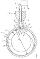
- the device shown in Fig. 1 for spectroscopic Investigation of plasticized extrudates points an extruder 1 with a housing 3 and an extruder screw trained conveyor 2 and a side of the screw conveyor 2 arranged measuring device 10 on.
- the measuring device 10 is provided with a radiation source 11 for generating electromagnetic radiation 12 and a sensor 15 for the determination of absorption spectra fitted.
- D is the outer diameter of the extruder screw 2 designated, wherein the extruder screw 2 on the periphery of a Slug 2b has arranged turns 2a.
- the diameter D of the extruder screw 2 corresponds to the embodiment shown substantially the inner diameter of the extruder housing 3.
- a reflection area 13 is the diameter D of the extruder screw 2nd recessed radially by a path length d.
- the path length d is smaller than that Height s of the turns 2a of the extruder screw 2.
- Die Extruder screw 2 has at least the reflection region 13 is a substantially radially directed, smooth surface on and is, for example, galvanically coated, especially hard chromed.
- the surface of the extruder screw 2 can be on the reflection region 13 either circular segment be curved with a radius (D / 2-d), or it may be one or more, in the circumferential direction of the extruder screw 2 consecutive, flat reflection areas be provided in the latter Case the normal of the plane reflection area vertical with respect to the tangent to the circumference of the extruder screw is arranged.
- the housing 3 of the extruder 1 has the side of the measuring device 10 for the respective spectrum of the Radiation source 11 generated electromagnetic radiation permeable window 16 on.
- the window 16 is e.g. made of quartz, glass, sapphire or the like.
- the window 16 consists in particular of two separate window segments 16a, 16b for the radiation entering the extrudate 12 or the emerging from the extrudate radiation 14.
- an optical arrangement 17 for focusing the electromagnetic Radiation provided, for example several lenses (not shown) with changeable Can have focal length.
- the optical arrangement 17 is via light guides 18, e.g. Glass fibers, with the radiation source 11 or connected to the sensor 15.
- the extruder screw 2 on the one hand in a conventional manner in the extruder housing 3 storable is a simple retrofit known extrusion devices with a Measuring device according to the invention possible by the Housing of the extrusion device laterally of the extruder screw with one for electromagnetic radiation permeable window equipped, the measuring device arranged and the extruder screw under training one with the path length d of the housing inner wall of the Extrusion device spaced, smooth, with respect the diameter of the extruder screw vertical reflection range e.g. abraded, milled or the like. and optionally electroplated.
- the diameter D of the extruder screw can be 2d smaller than the inside diameter of the Extruder housing and the reflection area on one Circumferential area of the screw can be arranged.
- the extruder screw for example, on a stored central drive shaft of the extruder housing be.
- the radiation source For example, 11 generates a continuous spectrum electromagnetic radiation 12 in a wavelength range from about 1 ⁇ m to about 10 ⁇ m (near-infrared region).
- the of the Radiation source 11 emitted radiation 12 via optical fibers 18, e.g. Glass fibers, in the optical arrangement 17th directed, which serves to focus the radiation 12.
- optical fibers 18, e.g. Glass fibers in the optical arrangement 17th directed, which serves to focus the radiation 12.
- optical fibers 18, e.g. Glass fibers in the optical arrangement 17th directed, which serves to focus the radiation 12.
- variable focal length optical arrangement 17 is the electromagnetic radiation 12 in dependence from the geometry of the extruder 1 or the screw conveyor 2, the refractive index of the extrudate etc. focusable.
- the radiation passes through 12, the window segment 16a of e.g.
- the window 16 has, as already mentioned, two each via a contact surface 16c juxtaposed window segments 16a, 16b on, wherein the electromagnetic radiation 12 through the Window segment 16a enters the extrudate and the Radiation 14 through the window segment 16b from the extrudate exit.
- the exiting radiation 14 affects by the contact surface 16c an "optical Isolation.
- the intensity would increase the emerging from the extrudate radiation 14 through the fraction reflected at the window / extrudate interface the incoming radiation 12 amplifies and the measuring sensitivity This reduces because the reflected Radiation the entire wavelength spectrum of the incoming Contains radiation and the absorbed spectral regions superimposed on the exiting radiation 14.
- the window 16 e.g. also two essentially round, concentrically arranged window segments exhibit. After exiting the window segment 16a occurs the electromagnetic radiation 12 substantially radially to the screw conveyor 2 in the interior 5 of the Housing 3 of the extruder 1 or in the plasticized Extrudate.
- the radiation 12a entering the extrudate enters the extrudate up to one of the distance between the inner wall 4 of the extruder housing 3 and the reflection area 13 of the extruder screw 2 set Path length d corresponding penetration depth and is on the reflection region 13 of the extruder screw 2 reflected.
- the reflected radiation 14a passes through this Extrude again with the path length d, so that the absorption path total is 2d.
- the one from the extrudate emerging radiation 14 is through the window segment 16b, the optical arrangement 17 and the light guides 18 of Measuring device 10 is passed to the sensor 15 and there for example, to determine the absorption line spectrum spektralzeraches.
- the absorption path of the electromagnetic radiation is variable by varying the path length d, so that the Device according to the invention as required for various on excitation with electromagnetic radiation with different wavelength ranges, e.g. microwaves, far infrared, infrared, near infrared, visible Light or ultraviolet, based absorption spectrometric Investigations is suitable.
- electromagnetic radiation with different wavelength ranges e.g. microwaves, far infrared, infrared, near infrared, visible Light or ultraviolet, based absorption spectrometric Investigations.
- This is either an extruder screw with several, mentioned above, in the circumferential direction successively arranged reflection areas equipped with different path length, wherein in the measurement, only those at the appropriate Reflection area reflected radiation considered or the auger can be replaced become.
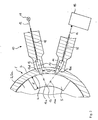
- Fig. 2 of an inventive Device is different from the design 1 characterized in that two arranged at a distance of 1 Single window 16d, 16e for entering the extrudate Radiation 12 and for emerging from the extrudate Radiation 14 is provided, which also has a achieved optical isolation of the emerging radiation 12 becomes.
- the mode of action corresponds to the above under Referring to Fig. 1 explained operation.
Landscapes
- Physics & Mathematics (AREA)
- Health & Medical Sciences (AREA)
- Life Sciences & Earth Sciences (AREA)
- Chemical & Material Sciences (AREA)
- Analytical Chemistry (AREA)
- Biochemistry (AREA)
- General Health & Medical Sciences (AREA)
- General Physics & Mathematics (AREA)
- Immunology (AREA)
- Pathology (AREA)
- Spectroscopy & Molecular Physics (AREA)
- Engineering & Computer Science (AREA)
- Mechanical Engineering (AREA)
- Investigating Or Analysing Materials By Optical Means (AREA)
- Extrusion Moulding Of Plastics Or The Like (AREA)
Abstract
Description
Die Erfindung betrifft ein Verfahren und eine Vorrichtung
zur spektroskopischen Untersuchung von plastifizierten
Extrudaten nach dem Oberbegriff des Anspruchs 1 bzw. 4.The invention relates to a method and a device
for the spectroscopic investigation of plasticized
Extrudates according to the preamble of
Extrusionsmaschinen oder Extruder sind in vielfältigen Ausführungen bekannt und dienen zur kontinuierlichen Verarbeitung von thermoplastischen Kunststoffen, wie Polyolefinen, Polyvinylchlorid, Polystyrol etc., zu Formteilen oder zur Herstellung pharmazeutischer Produkte, Lebensmittel oder dgl. Sie weisen in der Regel einen Auffülltrichter zum Bestücken des Extruders mit einem pulver-, granulat- oder agglomeratartigen Aufgabegut, eine in einem beheizbaren bzw. kühlbaren Gehäuse geführte Fördereinrichtung und einen Spritzkopf, z.B. eine Düse, auf. Die Fördereinrichtung ist in der Regel als gegebenenfalls stufenförmige Extruderschnecke oder auch als Kolben ausgebildet. Neben Einschneckenextrudern sind Zwei- oder Mehrschneckenextruder bekannt, die beispielsweise bei der Herstellung von Verbundwerkstoffen Verwendung finden.Extrusion machines or extruders are in manifold Designs known and used for continuous Processing of thermoplastics, such as Polyolefins, polyvinyl chloride, polystyrene, etc., to moldings or for the manufacture of pharmaceutical products, Food or the like. They usually have one Hopper for loading the extruder with a powder, granule or agglomerate-like feed, one guided in a heatable or coolable housing Conveyor and a spray head, e.g. a nozzle, on. The conveyor is usually as appropriate stepped extruder screw or as Piston formed. In addition to single-screw extruders are Two-screw or multi-screw extruders are known, for example in the manufacture of composites use Find.
Durch Extrudieren (Strangpressen) können beispielsweise Profile, Rohre, Schläuche, Kabelummantelungen oder dgl. hergestellt werden. Während der Extrusion kann die plastifizierte Formmasse bzw. das plastifizierte Extrudat verdichtet, gemischt, homogenisiert, ent- oder begast, vollständig aufgeschmolzen und/oder chemisch umgewandelt werden. Zur Kontrolle und Steuerung bzw. zur Optimierung solcher Prozesse ist es bekannt, den Druck und die Temperatur des plastifizierten Extrudates im Extruder kontinuierlich zu messen. Weiterhin ist es bekannt, die Farbe des plastifizierten Extrudates zu bestimmen, wobei insbesondere spektroskopische Verfahren verwendet werden, da diese sowohl qualitative als auch quantitative, schnelle und zerstörungsfreie Analysenverfahren darstellen.By extrusion (extrusion), for example Profiles, pipes, hoses, cable sheathing or the like. getting produced. During the extrusion, the plasticized Molding material or the plasticized extrudate compacted, mixed, homogenized, degassed or fumigated, completely melted and / or chemically converted become. For control and control or for optimization such processes it is known, the pressure and the temperature of the plasticized extrudate in the extruder continuously to eat. Furthermore, it is known the color to determine the plasticized extrudate, in particular spectroscopic methods are used since these are both qualitative and quantitative, fast and constitute non-destructive analytical methods.
Die DE 195 07 750 A1 beschreibt ein Verfahren zur kontinuierlichen Messung der Farbe von Extrudaten thermoplastischer Kunststoffe, wobei das Extrudat durch ein mit einer Flüssigkeit gefülltes Gefäß geleitet wird, in welche der Meßkopf eines Spektralphotometers eintaucht.DE 195 07 750 A1 describes a method for continuous Measurement of the color of extrudates thermoplastic Plastics, wherein the extrudate by a with a liquid filled vessel is passed, in which immerses the measuring head of a spectrophotometer.
Der DE 35 05 036 A1 ist ein Verfahren und eine Vorrichtung zur Regelung des Antriebs von Dosiereinrichtungen für die gesteuerte Zugabe von Farbkonzentraten und Zusatzstoffen in einen mit einer Grundkomponente dosiert beschickbaren Aufgabetrichter einer Schneckenmaschine zur Aufbereitung einer Fertigmischung nach Mischungsvorgabe entnehmbar, wobei die Fertigmischung in ihrer Farbintensität regelmäßig in kurzen Zeitabständen durch ein mit dem Austrittsende der Schneckenmaschine mittels einer Meßsonde verbundenes Spektrometer überprüft und zur Bildung eines Meßsignals für die gesteuerte Zugabe der Einzelkomponenten in einem mit einer Steuer- und Regeleinheit verbundenen Auswertegerät mit dem Sollwert der Farbintensität einer Standard-Mischung verglichen wird. Die Farbintensität wird nach dem Prinzip der Remissionsspektroskopie (Reflexionsspektroskopie) ermittelt, die auf der Untersuchung der von im wesentlichen lichtundurchlässigen, diffus streuenden Stoffen, wie Pigmenten, Farbstoffen oder dergleichen, reflektierten Strahlung beruht. Da das Remissionsspektrum lediglich Informationen über die Absorptions- und Streueigenschaften von mit Farbstoffen versetzten Stoffen enthält, ist eine insbesondere quantitative Bestimmung der chemischen Zusammensetzung von Extrudaten auf diese Weise nicht möglich.DE 35 05 036 A1 is a method and a device for controlling the drive of metering devices for the controlled addition of color concentrates and additives dosed into one with a basic component Chargeable feed hopper of a screw machine for Preparation of a ready mix according to the mixture specification removable, the finished mixture in their color intensity regularly at short intervals by one with the exit end of the screw machine by means of a Probe connected spectrometer checked and to Formation of a measuring signal for the controlled addition of Single components in one with a control unit connected evaluation device with the setpoint of Color intensity of a standard mixture is compared. The color intensity is based on the principle of reflectance spectroscopy (Reflection spectroscopy), the on examination of essentially opaque, diffusely scattering substances, such as pigments, Dyes or the like, reflected radiation based. Because the remission spectrum is just information about the absorption and scattering properties of with Colorants containing offset substances is one particular quantitative determination of the chemical composition of extrudates in this way not possible.
Zur Bestimmung der chemischen Zusammensetzung von plastifizierten Extrudaten im Extruder ist es bekannt, das Extrudat unmittelbar vor dem Austritt aus dem Extruder in einem Bereich zwischen Extruderschnecke und Spritzkopf mit einem kontinuierlichen Spektrum elektromagnetischer Strahlung zu bestrahlen und die aus dem Extrudat austretende Strahlung nach Wechselwirkung mit demselben spektroskopisch zu untersuchen. Hierbei wird insbesondere die auf dem Kirchhoff'schen Gesetz beruhende Absorptionsspektroskopie angewendet. Da nach dem Kirchhoff'schen Gesetz eine Substanz diejenige Strahlungsart absorbiert, die sie bei Anregung emittiert, absorbiert eine in den Strahlengang eines kontinuierlichen Spektrums gebrachte Substanz die für sie charakteristische Wellenlängen heraus, so daß ein für die jeweilige Substanz charakteristisches Absorptionslinienspektrum erhalten wird. Auf diese Weise können z.B. Aussagen über die chemische Zusammensetzung, die Reaktionskinetik oder die Feuchte des Extrudats erhalten werden.To determine the chemical composition of plasticized Extrudates in the extruder it is known that Extrudate immediately before exiting the extruder in a range between extruder screw and spray head with a continuous spectrum of electromagnetic Irradiating radiation and emerging from the extrudate Radiation after interaction with the same spectroscopically to investigate. Here is the particular Absorption spectroscopy based on Kirchoff's law applied. Because according to Kirchhoff's law a substance absorbs the kind of radiation that it contains emitted when excited absorbs one into the beam path a continuous spectrum brought substance the characteristic wavelengths out, so that a characteristic of the respective substance absorption line spectrum is obtained. That way you can e.g. Statements about the chemical composition, the Reaction kinetics or the moisture content of the extrudate become.
Nachteilig hierbei ist einerseits, daß die spektroskopische Untersuchung auf einen Bereich des Extruders zwischen Extruderschnecke und Spritzkopf beschränkt ist, so daß zwar die endgültige Zusammensetzung des Extrudates, nicht aber die zur Optimierung des Extrusionsprozesses erforderlichen Zusammensetzungen des Extrudates im Bereich der Extruderschnecke erfaßt werden können. Andererseits ist der Absorptionsweg der elektromagnetischen Strahlung im wesentlichen durch die Geometrie des Spritzkopfs des Extruders festgelegt, da im Bereich des Spritzkopfs aus strömungstechnischen Gründen keine Sensoren in den Schmelzekanal des Extrudes vorstehen dürfen. Der Absorptionsweg der elektromagnetischen Strahlung, der folglich in der Regel etwa dem Durchmesser des Extrudergehäuses zwischen Fördereinrichtung und Spritzkopf entspricht, kann somit für die jeweiligen gewünschten Spektralbereiche nicht optimiert werden, wobei der Absorptionsweg entweder zu kurz ist, so daß ein zu geringer Anteil der Strahlung absorbiert wird, oder der Absorptionsweg ist zu lang, so daß ein zu hoher Anteil der Strahlung absorbiert wird und die Strahlungsintensität der aus dem Extrudat austretenden Strahlung gering ist. Beides führt zu einer geringen Meßgenauigkeit und -empfindlichkeit.The disadvantage here is on the one hand, that the spectroscopic Examination on an area of the extruder is limited between extruder screw and spray head, so that, although the final composition of the extrudate, but not to optimize the extrusion process required compositions of the extrudate in Area of the extruder screw can be detected. on the other hand is the absorption path of the electromagnetic Radiation essentially by the geometry of the spray head of the extruder, since in the area of the spray head for flow reasons, no sensors in may protrude the melt channel of the Extrudes. Of the Absorption path of the electromagnetic radiation, the thus usually about the diameter of the extruder housing corresponds between conveyor and spray head, can thus for the respective desired spectral ranges not be optimized, the absorption path either too short, so one too low Share of radiation is absorbed, or the absorption path is too long, so that too high a proportion of Radiation is absorbed and the radiation intensity the exiting from the extrudate radiation is low. Both leads to a low accuracy and sensitivity.
Die EP 816 815 A1 zeigt ein Verfahren zur kontinuierlichen Farbmessung von Kunststoff-Formmassen, bei dem Licht über Sender-Lichtleiter und einen Sensorkopf in die Schmelze der Formmasse eingeleitet und das in dieser bzw. genauer in deren Randbereich reflektierte Licht über Empfängerlichtleiter zu einem Spektrometer oder Mehrbereichsphotometer geführt wird, wobei zumindest Sender-Lichtleiter oder Empfänger-Lichtleiter mehrfach vorhanden sind und einander zugeordnete Sender- und Empfängerlichtleiter jeweils gleichen Abstand voneinander aufweisen.EP 816 815 A1 shows a method for continuous Color measurement of plastic molding compounds, in which Light over transmitter light guide and a sensor head in the Introduced melt of the molding material and in this or more precisely in the edge region reflected light over Receiver light guide to a spectrometer or multi-range photometer is guided, wherein at least transmitter optical fiber or receiver optical fiber multiple available are and each associated transmitter and receiver light guide each have the same distance from each other.
Die JP 03-304995 A zeigt eine konstruktive Ausgestaltung zum radialen Einstrahlen von Licht in ein Extrudat und Reflektion an geneigten Stirnseitenflächen einer Extruderschnecke sowie Empfang der reflektierten Strahlung an ebenfalls geneigten Flächen im Austrittskanal des Extrudats.JP 03-304995 A shows a structural design for radially radiating light into an extrudate and Reflection on inclined faces of an extruder screw and receiving the reflected radiation also inclined surfaces in the outlet channel of the extrudate.
Die GB 1 593 474 zeigt die Reflektion an einem in einem fluidführenden Rohr befindlichen weiteren Rohr zur Absorptionsmessung.GB 1 593 474 shows the reflection on one in one fluid-carrying tube located further tube for absorption measurement.
Der Erfindung liegt daher die Aufgabe zugrunde, ein Verfahren der eingangs genannten Art vorzuschlagen, welches eine spektroskopische Untersuchung der plastifizierten Extrudate an einem beliebigen Bereich der Fördereinrichtung des Extruders und eine Optimierung des Absorptionsweges ermöglicht und somit eine hohe Meßgenauigkeit und -empfindlichkeit sicherstellt.The invention is therefore based on the object To propose method of the type mentioned, which is a spectroscopic study of the plasticized Extrudates on any area of the conveyor of the extruder and an optimization of the absorption path allows and thus a high accuracy and sensitivity.
Erfindungsgemäß wird diese Aufgabe bei einem Verfahren
der eingangs genannten Art durch die Merkmale des Anspruchs
1 gelöst. Zur Lösung sieht die Erfindung weiterhin
eine gattungsgemäße Vorrichtung mit den kennzeichnenden
Merkmalen des Anspruchs 4 vor.According to the invention, this object is achieved in a method
of the type mentioned by the features of the claim
1 solved. To solve the invention continues to see
a generic device with the characterizing
Features of
Erfindungsgemäß ist also vorgesehen, daß ein kontinuierliches Spektrum der elektromagnetischen Strahlung einer Strahlungsquelle durch die Extruderwand in das Extrudat eingekoppelt wird, dieses mit einer vorherbestimmbaren Weglänge durchläuft, an der Fördereinrichtung des Extruders reflektiert wird und das Extrudat nochmals im wesentlichen mit der gleichen Weglänge durchläuft, bevor es durch die Extruderwand aus dem Extrudat austritt. Die aus dem Extrudat ausgetretene elektromagnetische Strahlung kann beispielsweise über Lichtleitfasern zu einem Sensor weitergeleitet, spektralzerlegt und das Absorptionslinienspektrum bestimmt werden. Der Absorptionsweg der elektromagnetischen Strahlung kann durch Variation der dem Abstand zwischen Extruderwand und Fördereinrichtung entsprechenden Weglänge, welche dem halben Absorptionsweg entspricht, in Abhängigkeit des verwendeten Spektrums der Strahlung optimiert werden. Durch Variation des Absorptionsweges können somit je nach Art des Extrudates verschiedene Spektralbereiche elektromagnetischer Strahlung in das Extrudat eingekoppelt bzw. Absorptionslinienspektren der verschiedenen Spektralbereiche erhalten werden. Durch das erfindungsgemäße Verfahren können derartige Untersuchungen erstmals im Bereich der Fördereinrichtung des Extruders durchgeführt werden, ohne den Extrusionsprozeß zu beeinflussen. Hierdurch kann das Extrudat zu einem erheblich früheren Zeitpunkt untersucht werden, als es mit den Methoden gemäß dem Stand der Technik möglich ist, bei denen das Extrudat zwischen Fördereinrichtung und Spritzkopf, also unmittelbar vor Austritt aus dem Extruder, untersucht wird. Die in den verschiedenen Stadien des Extrusionsprozesses erhaltenen Meßwerte können beispielsweise zur Prozeßsteuerung, -regelung oder -optimierung verwendet werden.The invention thus provides that a continuous Spectrum of electromagnetic radiation one Radiation source through the extruder wall in the extrudate coupled with this one with a predictable Path length passes, at the conveyor of the extruder is reflected and the extrudate again substantially goes through it with the same path length before it exits the extrudate through the extruder wall. From the extrudate leaked electromagnetic radiation can, for example, via optical fibers to a sensor forwarded, spectrally decomposed and the absorption line spectrum be determined. The absorption path of the Electromagnetic radiation can be caused by variation of the the distance between extruder wall and conveyor corresponding path length, which is half the absorption path corresponds, depending on the spectrum used Radiation be optimized. By variation of the absorption path Thus, depending on the nature of the extrudate different Spectral ranges of electromagnetic radiation coupled into the extrudate or absorption line spectra the different spectral ranges are obtained. By the method according to the invention such Investigations for the first time in the area of the conveyor of the extruder, without the extrusion process to influence. This allows the extrudate to be investigated at a much earlier date than it is possible with the methods according to the prior art is where the extrudate is between conveyor and spray head, ie immediately before leaving the Extruder, is being investigated. The in the different Stages of the extrusion process obtained measurements For example, for process control, or regulation Optimization can be used.
Je nach charakteristischem Absorptionslinienspektrum des jeweiligen Extrudates kann dieses mit elektromagnetischer Strahlung mit einer Wellenlänge im Bereich von etwa 10 mm (Mikrowellen) bis zu etwa 10 nm (Ultraviolett) bestrahlt werden. Es kommen also sämtliche bekannten absorptionsspektroskopischen Untersuchungen, z.B. UV-Spektroskopie (Ultraviolett), VIS-Spektroskopie (sichtbares Licht), NIR-Spektroskopie (nahes Infrarot), IR-Spektroskopie (Infrarot) oder NMR- bzw. EPR-Spektroskopie (Mikro- bzw. Radiowellen), in Frage.Depending on the characteristic absorption line spectrum of the each extrudates this with electromagnetic Radiation with a wavelength in the range of about 10 mm (Microwaves) irradiated to about 10 nm (ultraviolet) become. So there are all known absorption spectroscopic Studies, e.g. UV spectroscopy (Ultraviolet), VIS spectroscopy (visible light), NIR spectroscopy (near infrared), IR spectroscopy (Infrared) or NMR or EPR spectroscopy (micro- or Radio waves), in question.
In bevorzugter Ausführung ist vorgesehen, daß pro Umdrehung der als Extruderschnecke ausgebildeten Fördereinrichtung wenigstens ein Absorptionsspektrum bestimmt wird. Es wird also immer dann wenigstens ein Absorptionsspektrum bestimmt, wenn die kontinuierlich rotierende Extruderschnecke eine zur Reflexion der elektromagnetischen Strahlung geeignete Anordnung bezüglich dem im wesentlichen radial zu derselben durch das Extrudergehäuse eingekoppelten elektromagnetischen Strahlung erreicht hat.In a preferred embodiment it is provided that per revolution the conveyor designed as an extruder screw determined at least one absorption spectrum becomes. So it is always at least one absorption spectrum determines if the continuously rotating Extruder screw one for reflection of the electromagnetic Radiation suitable arrangement with respect to the essentially radially to the same through the extruder housing reached coupled electromagnetic radiation Has.
Die Erfindung ist auch auf eine Vorrichtung zur Durchführung eines solchen Verfahrens gerichtet. Eine Vorrichtung zur spektroskopischen Untersuchung von plastifizierten Extrudaten, mit einem Extruder mit einem Gehäuse und einer Fördereinrichtung, wie einer Extruderschnecke, und wenigstens einer Meßeinrichtung mit einer Strahlungsquelle zur Erzeugung von elektromagnetischer Strahlung und einem Sensor zur Bestimmung von Absorptionsspektren, zeichnet sich dadurch aus, daß die Meßeinrichtung im Bereich der Fördereinrichtung des Extruders angeordnet ist, wobei die von der Strahlungsquelle erzeugte elektromagnetische Strahlung im wesentlichen radial zu der Fördereinrichtung in das Extrudat einbringbar, nach einer vorherbestimmbaren Weglänge an der Fördereinrichtung reflektierbar und das Absorptionsspektrum der aus dem Extrudat ausgetretenen Strahlung nach nochmaligem Durchlauf der Weglänge mittels des Sensors bestimmbar ist.The invention is also directed to an apparatus for carrying out directed to such a method. A device for the spectroscopic investigation of plasticized Extrudates, with an extruder with a housing and a conveyor, such as an extruder screw, and at least one measuring device with a radiation source for generating electromagnetic radiation and a sensor for determining absorption spectra, is characterized in that the measuring device in Area arranged the conveyor of the extruder is, wherein the electromagnetic generated by the radiation source Radiation substantially radially to the Conveyor introduced into the extrudate, after a Predeterminable path length at the conveyor reflectable and the absorption spectrum of the Extrudate leaked radiation after repeated passage the path length can be determined by means of the sensor.
Wie bereits erwähnt, ist die Fördereinrichtung bevorzugt als Extruderschnecke ausgebildet, wobei die Extruderschnecke beispielsweise entweder einen dem Innendurchmesser des Extrudergehäuses etwa entsprechenden Außendurchmesser, der ausschließlich am Reflexionsbereich um die dem halben Absorptionsweg entsprechende Weglänge verringert ist, aufweisen kann, oder der Außendurchmesser der Extruderschnecke ist um die dem Absorptionsweg entsprechende doppelte Weglänge kleiner als der Innendurchmesser des Extrudergehäuses und beispielsweise auf einer zentralen Welle des Extrudergehäuse gelagert.As already mentioned, the conveyor is preferred formed as an extruder screw, wherein the extruder screw for example, either one of the inner diameter the extruder housing about corresponding outer diameter, the only on the reflection area around the half-absorption path corresponding path length is reduced, may have, or the outer diameter the extruder screw is around the absorption path corresponding double path length smaller than the inner diameter the extruder housing and, for example a central shaft of the extruder housing stored.
In bevorzugter Ausführung ist vorgesehen, daß das Gehäuse des Extruders seitlich der Meßeinrichtung wenigstens ein Fenster zum Ein- und Austreten der elektromagnetischen Strahlung in das bzw. aus dem Extrudat aufweist. Um die aus dem Extrudat austretende elektromagnetische Strahlung von der in das Extrudat eintretenden Strahlung optisch zu isolieren, ist vorzugsweise ein aus zwei separaten Fenstersegmenten für die in das Extrudat eintretende Strahlung bzw. für die aus dem Extrudat austretende Strahlung bestehendes Fenster vorgesehen, wobei die Fenstersegmente z.B. nebeneinander oder im wesentlichen konzentrisch angeordnet sein können. Alternativ können zwei mit Abstand angeordnete Einzelfenster für die in das Extrudat eintretende Strahlung bzw. für die aus dem Extrudat austretende Strahlung vorgesehen sein.In a preferred embodiment it is provided that the housing of the extruder laterally of the measuring device at least one Window for entering and leaving the electromagnetic Radiation in and out of the extrudate. To the electromagnetic radiation emerging from the extrudate from the entering into the extrudate radiation optically isolate is preferably one of two separate Window segments for entering the extrudate Radiation or for emerging from the extrudate Provided radiation existing window, the Window segments e.g. next to each other or essentially can be arranged concentrically. Alternatively you can two spaced individual windows for in the Extrudate entering radiation or for the from the Extrudate emerging radiation may be provided.
Um insbesondere bei Koextrusionsprozessen und/oder bei mit einer chemischen Reaktion bzw. Be- und Entgasungsvorgängen oder dgl. einhergehenden Extrusionsprozessen eine optimale Prozeßsteuerung und -kontrolle zu erreichen, ist in bevorzugter Ausführung vorgesehen, daß die Vorrichtung zwei oder mehrere, insbesondere in Längsrichtung der Fördereinrichtung des Extruders beabstandete Meßeinrichtungen aufweist.In particular in coextrusion processes and / or in with a chemical reaction and / or degassing processes or the like accompanying extrusion processes achieving optimal process control and control is provided in a preferred embodiment that the device two or more, in particular in the longitudinal direction of Conveyor of the extruder spaced measuring devices having.
Nachstehend ist die Erfindung anhand von Ausführungsbeispielen unter Bezugnahme auf die Zeichnungen näher erläutert. Dabei zeigen:
- Fig. 1
- einen Querschnitt durch eine Ausführungsform einer erfindungsgemäßen Vorrichtung im Bereich der Meßeinrichtung und
- Fig. 2
- einen Detailschnitt durch eine weitere Ausführungsform.
- Fig. 1
- a cross-section through an embodiment of a device according to the invention in the region of the measuring device and
- Fig. 2
- a detail section through a further embodiment.
Die in Fig. 1 dargestellte Vorrichtung zur spektroskopischen
Untersuchung von plastifizierten Extrudaten weist
einen Extruder 1 mit einem Gehäuse 3 und einer als Extruderschnecke
ausgebildeten Fördereinrichtung 2 sowie eine
seitlich der Förderschnecke 2 angeordnete Meßeinrichtung
10 auf. Die Meßeinrichtung 10 ist mit einer Strahlungsquelle
11 zur Erzeugung von elektromagnetischer Strahlung
12 und einem Sensor 15 zur Bestimmung von Absorptionsspektren
ausgestattet. Wie aus der Zeichnung ersichtlich,
ist mit D der Außendurchmesser der Extruderschnecke 2
bezeichnet, wobei die Extruderschnecke 2 am Umfang eines
Schneckenkörpers 2b angeordnete Windungen 2a aufweist.
Der Durchmesser D der Extruderschnecke 2 entspricht in
der gezeigten Ausführungsform im wesentlichen dem Innendurchmesser
des Extrudergehäuses 3. An einem Reflexionsbereich
13 ist der Durchmesser D der Extruderschnecke 2
radial um eine Weglänge d ausgespart. In der dargestellten
Ausführungsform ist die Weglänge d kleiner als die
Höhe s der Windungen 2a der Extruderschnecke 2. Die
Extruderschnecke 2 weist zumindest am Reflexionsbereich
13 eine im wesentlichen radial gerichtete, glatte Oberfläche
auf und ist beispielsweise galvanisch beschichtet,
insbesondere hartverchromt. Die Oberfläche der Extruderschnecke
2 kann am Reflexionsbereich 13 entweder kreissegmentartig
mit einem Radius (D/2-d) gekrümmt sein, oder
es können ein oder mehrere, in Umfangsrichtung der Extruderschnecke
2 hintereinander angeordnete, ebene Reflexionsbereiche
vorgesehen sein, wobei in letztgenanntem
Fall die Normale des ebenen Reflexionsbereichs senkrecht
bezüglich der Tangente an den Umfang der Extruderschnecke
angeordnet ist.The device shown in Fig. 1 for spectroscopic
Investigation of plasticized extrudates points
an extruder 1 with a
Das Gehäuse 3 des Extruders 1 weist seitlich der Meßeinrichtung
10 ein für das jeweilige Spektrum der von der
Strahlungsquelle 11 erzeugten elektromagnetischen Strahlung
durchlässiges Fenster 16 auf. Das Fenster 16 besteht
z.B. aus Quarz, Glas, Saphir oder dgl. Das Fenster 16
besteht insbesondere aus zwei separaten Fenstersegmenten
16a, 16b für die in das Extrudat eintretende Strahlung 12
bzw. die aus dem Extrudat austretende Strahlung 14. Auf
der dem Extruder 1 abgewandten Seite des Fensters 16 ist
eine optische Anordnung 17 zur Fokussierung der elektromagnetischen
Strahlung vorgesehen, die beispielsweise
mehrere (nicht dargestellte) Linsen mit veränderbarer
Brennweite aufweisen kann. Die optische Anordnung 17 ist
über Lichtleiter 18, z.B. Glasfasern, mit der Strahlungsquelle
11 bzw. mit dem Sensor 15 verbunden.The
Durch die dargestellte Ausgestaltung ist die Extruderschnecke
2 einerseits auf herkömmliche Weise im Extrudergehäuse
3 lagerbar, andererseits ist eine einfache Nachrüstung
bekannter Extrusionsvorrichtungen mit einer
erfindungsgemäßen Meßeinrichtung möglich, indem das
Gehäuse der Extrusionsvorrichtung seitlich der Extruderschnecke
mit einem für elektromagnetische Strahlung
durchlässigen Fenster ausgestattet, die Meßeinrichtung
angeordnet und die Extruderschnecke unter Ausbildung
eines mit der Weglänge d von der Gehäuseinnenwand der
Extrusionsvorrichtung beabstandeten, glatten, bezüglich
des Durchmessers der Extruderschnecke senkrechten Reflexionsbereiches
z.B. abgeschliffen, -gefräst oder dgl.
und gegebenenfalls'galvanisch beschichtet wird. Alternativ
kann der Durchmesser D der Extruderschnecke beispielsweise
um 2d kleiner als der Innendurchmesser des
Extrudergehäuses und der Reflexionsbereich an einem
Umfangsbereich der Schnecke angeordnet sein. In diesem
Fall kann die Extruderschnecke beispielsweise auf einer
zentralen Antriebswelle des Extrudergehäuses gelagert
sein.Due to the illustrated embodiment, the extruder screw
2 on the one hand in a conventional manner in the
Nachfolgend ist die Wirkungsweise der erfindungsgemäßen
Meßeinrichtung 10 näher erläutert. Die Strahlungsquelle
11 erzeugt beispielsweise ein kontinuierliches Spektrum
elektromagnetischer Strahlung 12 in einem Wellenlängenbereich
von etwa 1 µm bis etwa 10 µm (Nahinfrarot-Bereich).
In der dargestellten Ausführung wird die von der
Strahlungsquelle 11 emittierte Strahlung 12 über Lichtleiter
18, z.B. Glasfasern, in die optische Anordnung 17
geleitet, die zur Fokussierung der Strahlung 12 dient.
Mittels der z.B. mehrere (nicht dargestellte) Linsen mit
veränderbarer Brennweite aufweisenden optischen Anordnung
17 ist die elektromagnetische Strahlung 12 in Abhängigkeit
von der Geometrie des Extruders 1 bzw. der Förderschnecke
2, des Brechungsindex des Extrudates etc. fokussierbar.
Nach der Fokussierung durchläuft die Strahlung
12 das Fenstersegment 16a des z.B. aus Quarz, Glas,
Saphir oder dgl. bestehenden, für das jeweilige Spektrum
durchlässigen Fensters 16. Das Fenster 16 weist, wie
bereits erwähnt, zwei über jeweils eine Berührungsfläche
16c nebeneinander angeordnete Fenstersegmente 16a, 16b
auf, wobei die elektromagnetische Strahlung 12 durch das
Fenstersegment 16a in das Extrudat eintritt und die
Strahlung 14 durch das Fenstersegment 16b aus dem Extrudat
austritt. Durch eine derartige Ausgestaltung des
Fensters 16 wird verhindert, daß der Anteil der eintretenden
Strahlung 12, welcher beim Eintritt in das Extrudat
bzw. beim Austritt aus dem Fenstersegment 16a Totalreflexion
erfährt, die austretende Strahlung 14 beeinträchtigt,
indem die Berührungsfläche 16c eine "optische
Isolation" darstellt. Andernfalls würde die Intensität
der aus dem Extrudat austretenden Strahlung 14 durch den
an der Grenzfläche Fenster/Extrudat reflektierten Anteil
der eintretenden Strahlung 12 verstärkt und die Meßempfindlichkeit
dadurch verringert, da die reflektierte
Strahlung das gesamte Wellenlängenspektrum der eintretenden
Strahlung enthält und die absorbierten Spektralbereiche
der austretenden Strahlung 14 überlagert. Je nach
Strahlengang kann das Fenster 16 z.B. auch zwei im wesentlichen
runde, konzentrisch angeordnete Fenstersegmente
aufweisen. Nach Austritt aus dem Fenstersegment 16a
tritt die elektromagnetische Strahlung 12 im wesentlichen
radial zu der Förderschnecke 2 in den Innenraum 5 des
Gehäuses 3 des Extruders 1 bzw. in das plastifizierte
Extrudat ein.The following is the operation of the
Die in das Extrudat eingetretene Strahlung 12a tritt in
das Extrudat bis zu einer der durch den Abstand zwischen
der Innenwand 4 des Extrudergehäuses 3 und dem Reflexionsbereich
13 der Extruderschnecke 2 festgelegten
Weglänge d entsprechenden Eindringtiefe ein und wird an
dem Reflexionsbereich 13 der Extruderschnecke 2 reflektiert.
Die reflektierte Strahlung 14a durchläuft das
Extrudat erneut mit der Weglänge d, so daß der Absorptionsweg
insgesamt 2d beträgt. Die aus dem Extrudat
austretende Strahlung 14 wird durch das Fenstersegment
16b, die optische Anordnung 17 und die Lichtleiter 18 der
Meßeinrichtung 10 zu dem Sensor 15 geleitet und dort
beispielsweise zur Bestimmung des Absorptionslinienspektrums
spektralzerlegt.The
Der Absorptionsweg der elektromagnetischen Strahlung ist durch Variation der Weglänge d variierbar, so daß die erfindungsgemäße Vorrichtung bedarfsweise für verschiedene, auf Anregung mit elektromagnetischer Strahlung mit verschiedenen Wellenlängenbereichen, z.B. Mikrowellen, fernes Infrarot, Infrarot, nahes Infrarot, sichtbares Licht oder Ultraviolett, beruhenden absorptionsspektrometrischen Untersuchungen geeignet ist. Hierzu ist entweder eine Extruderschnecke mit mehreren, oben erwähnten, in Umfangsrichtung hintereinander angeordneten Reflexionsbereichen mit unterschiedlicher Weglänge ausgerüstet, wobei bei der Messung nur die an den jeweils geeigneten Reflexionsbereich reflektierte Strahlung berücksichtigt wird, oder die Schnecke kann ausgewechselt werden.The absorption path of the electromagnetic radiation is variable by varying the path length d, so that the Device according to the invention as required for various on excitation with electromagnetic radiation with different wavelength ranges, e.g. microwaves, far infrared, infrared, near infrared, visible Light or ultraviolet, based absorption spectrometric Investigations is suitable. This is either an extruder screw with several, mentioned above, in the circumferential direction successively arranged reflection areas equipped with different path length, wherein in the measurement, only those at the appropriate Reflection area reflected radiation considered or the auger can be replaced become.
Bei rotierender Extruderschnecke 2 ist wenigstens eine
Messung pro Umdrehung der Schnecke 2 durchführbar, nämlich
dann, wenn der Reflexionsbereich 13 der Schnecke 2
eine dem Fenster 16 der Meßeinrichtung 10 zugewandte
Stellung erreicht.When rotating extruder screw 2 is at least one
Measurement per revolution of the screw 2 feasible, namely
when the
Die in Fig. 2 gezeigte Ausführungsform einer erfindungsgemäßen
Vorrichtung unterscheidet sich von der Ausführung
gemäß Fig. 1 dadurch, daß zwei mit Abstand 1 angeordnete
Einzelfenster 16d, 16e für die in das Extrudat eintretende
Strahlung 12 bzw. für die aus dem Extrudat austretende
Strahlung 14 vorgesehen ist, wodurch ebenfalls eine
optische Isolation der austretenden Strahlung 12 erreicht
wird. Die Wirkungsweise entspricht der vorstehend unter
Bezugnahme auf Fig. 1 erläuterten Wirkungsweise. The embodiment shown in Fig. 2 of an inventive
Device is different from the design
1 characterized in that two arranged at a distance of 1
- 11
- Extruderextruder
- 22
- Extruderschneckeextruder screw
- 2a2a
- Windungenturns
- 2b2 B
- Schneckenkörperscrew body
- 33
- Extrudergehäuseextruder barrel
- 44
- Innenwand des ExtrudergehäusesInner wall of the extruder housing
- 55
- Innenraum des ExtrudergehäusesInterior of the extruder housing
- 1010
- Meßeinrichtungmeasuring device
- 1111
- Strahlungsquelleradiation source
- 12,12a12,12a
- eintretende Strahlungincoming radiation
- 1313
- Reflexionsbereichreflection area
- 14,14a14,14a
- austretende Strahlungemerging radiation
- 1515
- Sensorsensor
- 1616
- Fensterwindow
- 16a, 16b16a, 16b
- Fenstersegmentewindow segments
- 16c16c
- Berührungsfläche der FenstersegmenteContact surface of the window segments
- 16d, 16e16d, 16e
- EinzelfensterSingle window
- 1717
- optische Anordnungoptical arrangement
- 1818
- Lichtleiternlight guides
- DD
- Durchmesser der FördereinrichtungDiameter of the conveyor
- dd
- Weglänge der ein- bzw. austretenden StrahlungPath length of incoming and outgoing radiation
- ss
- Höhe der WindungenHeight of the turns
- ll
- Abstand zwischen den EinzelfensternDistance between the single windows
Claims (10)
- Method for spectroscopic examination of the chemical composition of plasticised extrudates in an extruder (1) having a conveying device (2), such as an extruder screw, by irradiating the extrudate with electromagnetic radiation (12) and spectroscopically examining the radiation (14) emerging from the extrudate after interacting with with the same, characterised in that the extrudate is irradiated with electromagnetic radiation (12) in a wavelength range of approximately 10 mm to approximately 10 nm, in the region of the conveying device (2) of the extruder (1) substantially radially to the same, the radiation (12a) which has entered the extrudate is reflected at the conveying device (2) after a path length (d) which can be determined in advance and the absorption spectrum of the radiation (14), which has emerged from the extrudate after passing again along the path length (d), is determined.
- Method according to claim 1, characterised in that the extrudate is irradiated with electromagnetic radiation with a wavelength in the range of approximately 10 mm (microwaves) to approximately 10 nm (ultraviolet).
- Method according to claim 1 or 2, characterised in that, per rotation of the conveying device (2), which is configured as an extruder screw, at least one absorption spectrum is determined.
- Device for spectroscopic examination of the chemical composition of plasticised extrudates, having an extruder (1) with a housing (3) and a conveying device (2), such as an extruder screw, and having at least one measuring device (10) with a radiation source (11) for generating electromagnetic radiation (12) and having a sensor (15) for determining absorption spectra, in particular for implementing a method according to one of the claims 1 to 3, characterised in that the measuring device (10) is disposed in the region of the conveying device (2) of the extruder (1), the electromagnetic radiation (12), which has a wavelength range of approximately 10 mm to approximately 10 nm and is generated by the radiation source (11), being able to be introduced into the extrudate substantially radially relative to the conveying device (2), being able to be reflected at the conveying device after a path length (d) which can be determined in advance and the absorption spectrum of the radiation, which has emerged from the extrudate after passing again along the path length (d), being able to be determined by means of the sensor (15).
- Device according to claim 4, characterised in that the conveying device (2) is configured as an extruder screw.
- Device according to claim 4 or 5, characterised in that the housing (3) of the extruder (1), laterally of the measuring device (10), has at least one window (16) for entrance and emergence of the electromagnetic radiation (12, 14) into or out of the extrudate.
- Device according to one of the claims 4 to 6, characterised in that one window (16) is provided which comprises two separate window segments (16a, 16b) for the radiation (12) which is entering the extrudate or for the radiation (14) which is emerging from the extrudate.
- Device according to claim 7, characterised in that the window segments (16a, 16b) are disposed adjacent to each other, or substantially concentrically.
- Device according to one of the claims 4 to 6, characterised in that two individual windows (16d, 16e), which are disposed at a spacing (1), are provided for the radiation (12) which is entering the extrudate or for the radiation (14) which is emerging from the extrudate.
- Device according to one of the claims 4 to 9 having at least two measuring devices (10).
Applications Claiming Priority (2)
| Application Number | Priority Date | Filing Date | Title |
|---|---|---|---|
| DE19932746A DE19932746B4 (en) | 1999-07-14 | 1999-07-14 | Method and apparatus for the spectroscopic examination of plasticized extrudates |
| DE19932746 | 1999-07-14 |
Publications (3)
| Publication Number | Publication Date |
|---|---|
| EP1069415A2 EP1069415A2 (en) | 2001-01-17 |
| EP1069415A3 EP1069415A3 (en) | 2002-11-06 |
| EP1069415B1 true EP1069415B1 (en) | 2005-09-28 |
Family
ID=7914639
Family Applications (1)
| Application Number | Title | Priority Date | Filing Date |
|---|---|---|---|
| EP00114378A Expired - Lifetime EP1069415B1 (en) | 1999-07-14 | 2000-07-05 | Method and apparatus for a spectroscopic examination of plasticized extrudates |
Country Status (3)
| Country | Link |
|---|---|
| EP (1) | EP1069415B1 (en) |
| AT (1) | ATE305604T1 (en) |
| DE (2) | DE19932746B4 (en) |
Families Citing this family (2)
| Publication number | Priority date | Publication date | Assignee | Title |
|---|---|---|---|---|
| DE102011113543A1 (en) * | 2011-09-15 | 2013-03-21 | Klöckner Pentaplast GmbH & Co. KG | Colored polymeric moldings, process and apparatus for producing the moldings |
| CN115003485B (en) * | 2020-01-20 | 2024-04-16 | 优泊公司 | Method and system for producing molded body |
Family Cites Families (7)
| Publication number | Priority date | Publication date | Assignee | Title |
|---|---|---|---|---|
| DE2810388A1 (en) * | 1977-03-14 | 1978-09-21 | Bindicator Co | DEVICE FOR OPTICAL MEASUREMENT OF A PRESELECTED PROPERTY OF A SUBSTANCE FLOWING IN A LINE |
| DE3505036C2 (en) * | 1985-02-14 | 1987-02-26 | Werner & Pfleiderer, 7000 Stuttgart | Device for the controlled addition of color concentrates into a screw machine |
| JPH06304995A (en) * | 1993-04-22 | 1994-11-01 | Fujikura Ltd | Mesh breakage sensing device for resin molding machine |
| DE19507750A1 (en) * | 1995-03-06 | 1996-09-12 | Bayer Ag | Continuous direct determn. of colour of thermoplastic synthetic extrudate |
| US5650484A (en) * | 1995-07-12 | 1997-07-22 | Xerox Corporation | Feedback control system for polymer modification of toner resins and toners |
| DE19626785A1 (en) * | 1996-07-03 | 1998-01-08 | Basf Ag | Process and device for the continuous color measurement of plastic molding compounds |
| DE19646394C1 (en) * | 1996-11-07 | 1998-04-30 | Roehm Gmbh | Extrusion system and process for extrusion with minimized color change times |
-
1999
- 1999-07-14 DE DE19932746A patent/DE19932746B4/en not_active Expired - Fee Related
-
2000
- 2000-07-05 DE DE50011239T patent/DE50011239D1/en not_active Expired - Fee Related
- 2000-07-05 EP EP00114378A patent/EP1069415B1/en not_active Expired - Lifetime
- 2000-07-05 AT AT00114378T patent/ATE305604T1/en not_active IP Right Cessation
Also Published As
| Publication number | Publication date |
|---|---|
| EP1069415A2 (en) | 2001-01-17 |
| ATE305604T1 (en) | 2005-10-15 |
| DE50011239D1 (en) | 2005-11-03 |
| DE19932746B4 (en) | 2005-11-10 |
| EP1069415A3 (en) | 2002-11-06 |
| DE19932746A1 (en) | 2001-01-25 |
Similar Documents
| Publication | Publication Date | Title |
|---|---|---|
| DE4004627C2 (en) | Method for determining material properties of polymer materials and device for carrying out the method | |
| DE60211010T2 (en) | SPECTROSCOPIC LIQUID ANALYZER | |
| EP2177342B1 (en) | Extrusion transport device | |
| EP0163847B1 (en) | Interferential refractometer | |
| EP1472521A1 (en) | Method for analysing liquids, in addition to a device therefor | |
| DE10361058B3 (en) | Highly accurate flow-oriented multi-angle reflectance sensor | |
| DE102010062268B4 (en) | Absorption measuring device | |
| EP4160188B1 (en) | Thz measuring device and thz measuring method for measuring a conveyed test object | |
| DE112017008060T5 (en) | Accessory for an infrared spectrometer | |
| EP0995076A1 (en) | Method and device for determining the thickness of paper or cardboard by measuring on a continuous material web | |
| WO2008014937A1 (en) | Optical measuring cell | |
| EP0584654A1 (en) | Method and device for continuous IR spectroscopic ATR analysis of highly viscous liquids | |
| DE19626785A1 (en) | Process and device for the continuous color measurement of plastic molding compounds | |
| WO2005047869A1 (en) | Flow-through measuring cell, spectrometer and method for analysing biological fluids | |
| WO2016083342A1 (en) | Process monitoring for uv curing | |
| EP1600761A1 (en) | Tabletting press with integrated NIR measurement device | |
| DE19932746B4 (en) | Method and apparatus for the spectroscopic examination of plasticized extrudates | |
| DE19811150C2 (en) | Thin-layer chromatography | |
| EP1646858B1 (en) | Reflectance sensor for measuring liquid pigment preparations or solid pigmented surfaces | |
| WO1992006366A1 (en) | Device for the qualitative and/or quantitative determination of the compositon of a sample to be analysed | |
| DE69000332T2 (en) | MEASURING A GAP BETWEEN A TUBE AND A FLOAT. | |
| DE102013013902B4 (en) | Temperature gradient determination in the melting chamber | |
| DE3942375A1 (en) | DEVICE FOR SIMULTANEOUS DETECTION OF SEVERAL WAVELENGTH RANGES | |
| DE19820948C1 (en) | Machine controlling plastic granule quality under realistic conditions | |
| DE102017108552A1 (en) | Spectrometric measuring head with several transmission light entry windows |
Legal Events
| Date | Code | Title | Description |
|---|---|---|---|
| PUAI | Public reference made under article 153(3) epc to a published international application that has entered the european phase |
Free format text: ORIGINAL CODE: 0009012 |
|
| AK | Designated contracting states |
Kind code of ref document: A2 Designated state(s): AT BE CH CY DE DK ES FI FR GB GR IE IT LI LU MC NL PT SE |
|
| AX | Request for extension of the european patent |
Free format text: AL;LT;LV;MK;RO;SI |
|
| PUAL | Search report despatched |
Free format text: ORIGINAL CODE: 0009013 |
|
| AK | Designated contracting states |
Kind code of ref document: A3 Designated state(s): AT BE CH CY DE DK ES FI FR GB GR IE IT LI LU MC NL PT SE |
|
| AX | Request for extension of the european patent |
Free format text: AL;LT;LV;MK;RO;SI |
|
| 17P | Request for examination filed |
Effective date: 20030120 |
|
| AKX | Designation fees paid |
Designated state(s): AT DE ES FR GB IT |
|
| 17Q | First examination report despatched |
Effective date: 20030905 |
|
| RAP1 | Party data changed (applicant data changed or rights of an application transferred) |
Owner name: FRAUNHOFER-GESELLSCHAFT ZUR FOERDERUNG DERANGEWAND |
|
| GRAP | Despatch of communication of intention to grant a patent |
Free format text: ORIGINAL CODE: EPIDOSNIGR1 |
|
| GRAS | Grant fee paid |
Free format text: ORIGINAL CODE: EPIDOSNIGR3 |
|
| GRAA | (expected) grant |
Free format text: ORIGINAL CODE: 0009210 |
|
| AK | Designated contracting states |
Kind code of ref document: B1 Designated state(s): AT DE ES FR GB IT |
|
| PG25 | Lapsed in a contracting state [announced via postgrant information from national office to epo] |
Ref country code: IT Free format text: LAPSE BECAUSE OF FAILURE TO SUBMIT A TRANSLATION OF THE DESCRIPTION OR TO PAY THE FEE WITHIN THE PRESCRIBED TIME-LIMIT;WARNING: LAPSES OF ITALIAN PATENTS WITH EFFECTIVE DATE BEFORE 2007 MAY HAVE OCCURRED AT ANY TIME BEFORE 2007. THE CORRECT EFFECTIVE DATE MAY BE DIFFERENT FROM THE ONE RECORDED. Effective date: 20050928 Ref country code: GB Free format text: LAPSE BECAUSE OF FAILURE TO SUBMIT A TRANSLATION OF THE DESCRIPTION OR TO PAY THE FEE WITHIN THE PRESCRIBED TIME-LIMIT Effective date: 20050928 |
|
| REG | Reference to a national code |
Ref country code: GB Ref legal event code: FG4D Free format text: NOT ENGLISH |
|
| REF | Corresponds to: |
Ref document number: 50011239 Country of ref document: DE Date of ref document: 20051103 Kind code of ref document: P |
|
| PG25 | Lapsed in a contracting state [announced via postgrant information from national office to epo] |
Ref country code: ES Free format text: LAPSE BECAUSE OF FAILURE TO SUBMIT A TRANSLATION OF THE DESCRIPTION OR TO PAY THE FEE WITHIN THE PRESCRIBED TIME-LIMIT Effective date: 20060108 |
|
| GBV | Gb: ep patent (uk) treated as always having been void in accordance with gb section 77(7)/1977 [no translation filed] |
Effective date: 20050928 |
|
| PLBE | No opposition filed within time limit |
Free format text: ORIGINAL CODE: 0009261 |
|
| STAA | Information on the status of an ep patent application or granted ep patent |
Free format text: STATUS: NO OPPOSITION FILED WITHIN TIME LIMIT |
|
| 26N | No opposition filed |
Effective date: 20060629 |
|
| EN | Fr: translation not filed | ||
| PG25 | Lapsed in a contracting state [announced via postgrant information from national office to epo] |
Ref country code: FR Free format text: LAPSE BECAUSE OF FAILURE TO SUBMIT A TRANSLATION OF THE DESCRIPTION OR TO PAY THE FEE WITHIN THE PRESCRIBED TIME-LIMIT Effective date: 20061124 |
|
| PG25 | Lapsed in a contracting state [announced via postgrant information from national office to epo] |
Ref country code: DE Free format text: LAPSE BECAUSE OF NON-PAYMENT OF DUE FEES Effective date: 20070201 |
|
| PG25 | Lapsed in a contracting state [announced via postgrant information from national office to epo] |
Ref country code: AT Free format text: LAPSE BECAUSE OF NON-PAYMENT OF DUE FEES Effective date: 20060705 |
|
| PG25 | Lapsed in a contracting state [announced via postgrant information from national office to epo] |
Ref country code: FR Free format text: LAPSE BECAUSE OF FAILURE TO SUBMIT A TRANSLATION OF THE DESCRIPTION OR TO PAY THE FEE WITHIN THE PRESCRIBED TIME-LIMIT Effective date: 20050928 |