EP1069379A2 - Anlage zur Gewinnung von Wärmeenergie, insbesondere von Sonnenergie, und Verfahren zu deren Steuerung - Google Patents
Anlage zur Gewinnung von Wärmeenergie, insbesondere von Sonnenergie, und Verfahren zu deren Steuerung Download PDFInfo
- Publication number
- EP1069379A2 EP1069379A2 EP00890217A EP00890217A EP1069379A2 EP 1069379 A2 EP1069379 A2 EP 1069379A2 EP 00890217 A EP00890217 A EP 00890217A EP 00890217 A EP00890217 A EP 00890217A EP 1069379 A2 EP1069379 A2 EP 1069379A2
- Authority
- EP
- European Patent Office
- Prior art keywords
- heat
- sensor
- collector
- pump
- control unit
- Prior art date
- Legal status (The legal status is an assumption and is not a legal conclusion. Google has not performed a legal analysis and makes no representation as to the accuracy of the status listed.)
- Withdrawn
Links
- 238000000034 method Methods 0.000 title claims abstract description 6
- 238000004519 manufacturing process Methods 0.000 title claims description 3
- 230000004913 activation Effects 0.000 claims 1
- 238000009434 installation Methods 0.000 claims 1
- 238000000605 extraction Methods 0.000 abstract 2
- XLYOFNOQVPJJNP-UHFFFAOYSA-N water Substances O XLYOFNOQVPJJNP-UHFFFAOYSA-N 0.000 description 10
- 238000005338 heat storage Methods 0.000 description 4
- 238000010438 heat treatment Methods 0.000 description 2
- 238000010521 absorption reaction Methods 0.000 description 1
- 230000005540 biological transmission Effects 0.000 description 1
- 230000001143 conditioned effect Effects 0.000 description 1
- 238000011084 recovery Methods 0.000 description 1
Images
Classifications
-
- F—MECHANICAL ENGINEERING; LIGHTING; HEATING; WEAPONS; BLASTING
- F24—HEATING; RANGES; VENTILATING
- F24D—DOMESTIC- OR SPACE-HEATING SYSTEMS, e.g. CENTRAL HEATING SYSTEMS; DOMESTIC HOT-WATER SUPPLY SYSTEMS; ELEMENTS OR COMPONENTS THEREFOR
- F24D19/00—Details
- F24D19/10—Arrangement or mounting of control or safety devices
- F24D19/1006—Arrangement or mounting of control or safety devices for water heating systems
- F24D19/1009—Arrangement or mounting of control or safety devices for water heating systems for central heating
- F24D19/1042—Arrangement or mounting of control or safety devices for water heating systems for central heating the system uses solar energy
-
- F—MECHANICAL ENGINEERING; LIGHTING; HEATING; WEAPONS; BLASTING
- F24—HEATING; RANGES; VENTILATING
- F24H—FLUID HEATERS, e.g. WATER OR AIR HEATERS, HAVING HEAT-GENERATING MEANS, e.g. HEAT PUMPS, IN GENERAL
- F24H15/00—Control of fluid heaters
- F24H15/30—Control of fluid heaters characterised by control outputs; characterised by the components to be controlled
- F24H15/335—Control of pumps, e.g. on-off control
-
- Y—GENERAL TAGGING OF NEW TECHNOLOGICAL DEVELOPMENTS; GENERAL TAGGING OF CROSS-SECTIONAL TECHNOLOGIES SPANNING OVER SEVERAL SECTIONS OF THE IPC; TECHNICAL SUBJECTS COVERED BY FORMER USPC CROSS-REFERENCE ART COLLECTIONS [XRACs] AND DIGESTS
- Y02—TECHNOLOGIES OR APPLICATIONS FOR MITIGATION OR ADAPTATION AGAINST CLIMATE CHANGE
- Y02B—CLIMATE CHANGE MITIGATION TECHNOLOGIES RELATED TO BUILDINGS, e.g. HOUSING, HOUSE APPLIANCES OR RELATED END-USER APPLICATIONS
- Y02B10/00—Integration of renewable energy sources in buildings
- Y02B10/20—Solar thermal
-
- Y—GENERAL TAGGING OF NEW TECHNOLOGICAL DEVELOPMENTS; GENERAL TAGGING OF CROSS-SECTIONAL TECHNOLOGIES SPANNING OVER SEVERAL SECTIONS OF THE IPC; TECHNICAL SUBJECTS COVERED BY FORMER USPC CROSS-REFERENCE ART COLLECTIONS [XRACs] AND DIGESTS
- Y02—TECHNOLOGIES OR APPLICATIONS FOR MITIGATION OR ADAPTATION AGAINST CLIMATE CHANGE
- Y02B—CLIMATE CHANGE MITIGATION TECHNOLOGIES RELATED TO BUILDINGS, e.g. HOUSING, HOUSE APPLIANCES OR RELATED END-USER APPLICATIONS
- Y02B10/00—Integration of renewable energy sources in buildings
- Y02B10/70—Hybrid systems, e.g. uninterruptible or back-up power supplies integrating renewable energies
Definitions
- the subject invention relates to a system for the production of thermal energy, in particular solar energy, with a heat collector, a heat store connected to it with a heat exchanger, a feed pump, a control unit and with the heat collector and the heat store associated heat sensors, the outputs of which are connected to the control unit .
- the invention further relates to a method for controlling such a system.
- a known system of this type consists of a heat collector and a heat store connected to this, e.g. a hot water tank, with a heat exchanger, which heated in the heat collector Carrier medium by means of a pump through the heat exchanger and is then conveyed back to the heat collector.
- a heat exchanger which heated in the heat collector Carrier medium by means of a pump through the heat exchanger and is then conveyed back to the heat collector.
- the warm or hot carrier medium from the heat exchanger to the im Heat stored water released, which as hot water for is used for consumption or for heating purposes.
- a first heat sensor is that Assigned output of the heat collector.
- the second heat sensor is located in the upper area of the heat accumulator.
- the pump is switched on, which in the heat collector heated carrier medium in the in the heat storage Heat exchanger is promoted in which the carrier medium Gives heat content to the water in the heat storage, whereupon the cooled carrier medium is returned to the heat collector.
- the pump is switched off again by the control unit.
- the object of the invention is therefore to create a system by which a much better efficiency is achieved without heat loss occurring.
- This is achieved according to the invention in that a third heat sensor is provided, which is assigned to the carrier medium flowing back from the heat exchanger to the heat collector.
- the third heat sensor is preferably inserted into the return line of the heat exchanger.
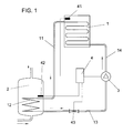
- FIG. 1 shows a plant for heat recovery in a schematic Presentation.
- This system consists of a heat collector 1, the flow of which is via a Line 11 to a heat exchanger 12 located in the heat accumulator 2 connected.
- a line 13 leads from the heat exchanger 12 to one Pump 3, from which a line 14 to the return of the heat collector 1 leads.
- a carrier medium In the closed circuit of the heat accumulator 1 and the heat exchanger 12 is a carrier medium.
- the pump 3 is controlled by a control unit 4.
- a first heat sensor 41 provided in the heat collector 1 and a second heat sensor 42 provided in the upper region of the heat accumulator 2 are connected to the control unit 1.
- a third heat sensor 43 is arranged in the line 13 leading away from the heat exchanger 2.
- the hot carrier medium located in the heat collector 1 is conveyed into the heat exchanger 12, in which the heat is released to the cold water located in the heat accumulator 2, as a result of which the latter is heated.
- This warm or hot water can be used for consumption or for heating purposes.
- the pump 3 is not controlled by the second heat sensor 42, but rather by the third heat sensor 43, which only switches off the pump 3 as soon as the one indicated by it Temperature value has risen to a value which is one predetermined value of e.g. likewise 5 ° C below that of the first Heat sensor 41 displayed temperature value.
- This also serves a differential circuit by which the pump 3 is switched off.
- the procedure for operating such a system is as follows: If, for example, the first heat sensor 41 shows a temperature of 50 ° C. and the second heat sensor 42 shows a temperature of 30 ° C., the control unit 4 switches on the pump 5, as a result of which heat in the heat collector 1 is transferred from the heat collector 1 to the heat exchanger by the hot carrier medium 12 is transmitted, from which the heat is released to the water located in the heat accumulator 2. Since the heat sensor 42 is subsequently not decisive, the temperature value displayed by the temperature sensor 42 can rise as desired, regardless of the temperature value of the first heat sensor 41, without a control process taking place.
- the specified difference in temperatures can also be used with another Value, e.g. at 2 ° C.
Landscapes
- Engineering & Computer Science (AREA)
- Physics & Mathematics (AREA)
- Thermal Sciences (AREA)
- Chemical & Material Sciences (AREA)
- Combustion & Propulsion (AREA)
- Mechanical Engineering (AREA)
- General Engineering & Computer Science (AREA)
- Life Sciences & Earth Sciences (AREA)
- Sustainable Development (AREA)
- Sustainable Energy (AREA)
- Central Heating Systems (AREA)
Abstract
Description
Weiters betrifft die Erfindung ein Verfahren zur Steuerung einer derartigen Anlage.
Vorzugsweise ist der dritte Wärmefühler in die Rücklaufleitung des Wärmetauschers eingesetzt.
Die Wirkungsweise dieser Anlage ist wie folgt:
Sobald der vom ersten Wärmefühler 41 angezeigte Temperaturwert, welcher die Vorlauftemperatur des Wärmekollektors 1 darstellt, über einen vorgegebenen Wert von z.B. 5°C, des vom zweiten Temperaturfühler 42 angezeigten Temperaturwertes angestiegen ist, spricht eine in der Steuereinheit 4 befindliche Differenzschaltung an, wodurch die Pumpe 3 eingeschaltet wird. Hierdurch wird das im Wärmekollektor 1 befindliche heiße Trägermedium in den Wärmetauscher 12 gefördert, in welchem die Wärme an das im Wärmespeicher 2 befindliche kalte Wasser abgegeben wird, wodurch dieses erwärmt wird. Dieses warme bzw. heiße Wasser kann für den Verbrauch oder für Heizungszwecke verwendet werden.
Soferne z.B. der erste Wärmefühler 41 eine Temperatur von 50°C und der zweite Wärmefühler 42 eine Temperatur von 30°C anzeigt, schaltet die Steuereinheit 4 die Pumpe 5 ein, wodurch im Wärmekollektor 1 befindliche Wärme durch das heiße Trägermedium vom Wärmekollektor 1 auf den Wärmetauscher 12 übertragen wird, von welchem die Wärme an das im Wärmespeicher 2 befindliche Wasser abgegeben wird. Da in weiterer Folge der Wärmefühler 42 nicht maßgeblich ist, kann der vom Temperaturfühler 42 angezeigte Temperaturwert unabhängig vom Temperaturwert des erste Wärmefühlers 41 beliebig ansteigen, ohne daß ein Steuerungsvorgang erfolgt. Vielmehr ist für die Abschaltung der Pumpe 3 nur der dritte Temperaturfühler 43 maßgeblich, da erst dann eine Abschaltung der Pumpe 3 erfolgt, sobald der vom dritten Temperaturfühler 43 angezeigte Temperaturwert auf einen Wert angestiegen ist, welcher z.B. um 5°C unter demjenigen des vom ersten Temperaturfühler 41 angezeigten Wertes liegt.
Claims (3)
- Anlage zur Gewinnung von Wärmeenergie, insbesondere von Sonnenenergie mit einem Wärmekollektor (1), einem an diesen angeschlossenen Wärmespeicher (2) mit einem Wärmetauscher (12), einer Förderpumpe (3), einer Steuereinheit (4) sowie mit dem Wärmekollektor (1) und dem Wärmespeicher (2) zugeordneten Wärmefühlern (41, 42), deren Ausgänge an die Steuereinheit (4) angeschlossen sind, dadurch gekennzeichnet, daß ein dritter Wärmefühler (43) vorgesehen ist, welcher dem vom Wärmetauscher (12) zum Wärmekollektor (1) zurückströmenden Trägermedium zugeordnet ist.
- Anlage nach Anspruch 1, dadurch gekennzeichnet, daß der dritte Wärmefühler (43) in die Rücklaufleitung (13) des Wärmetauschers (1) eingesetzt ist.
- Verfahren zur Steuerung einer Anlage nach einem der Ansprüche 1 und 2, dadurch gekennzeichnet, daß die Einschaltung der Pumpe (3) durch den im Wärmespeicher (2) befindlichen zweiten Wärmefühler (42) bewirkt wird und daß die Abschaltung der Pumpe (3) durch den dem zum Wärmekollektor (1) zurückströmenden Trägermedium zugeordneten dritten Wärmefühler (43) erfolgt.
Applications Claiming Priority (2)
| Application Number | Priority Date | Filing Date | Title |
|---|---|---|---|
| AT122899 | 1999-07-15 | ||
| AT122899 | 1999-07-15 |
Publications (2)
| Publication Number | Publication Date |
|---|---|
| EP1069379A2 true EP1069379A2 (de) | 2001-01-17 |
| EP1069379A3 EP1069379A3 (de) | 2002-11-20 |
Family
ID=3509387
Family Applications (1)
| Application Number | Title | Priority Date | Filing Date |
|---|---|---|---|
| EP00890217A Withdrawn EP1069379A3 (de) | 1999-07-15 | 2000-07-13 | Anlage zur Gewinnung von Wärmeenergie, insbesondere von Sonnenergie, und Verfahren zu deren Steuerung |
Country Status (1)
| Country | Link |
|---|---|
| EP (1) | EP1069379A3 (de) |
Cited By (1)
| Publication number | Priority date | Publication date | Assignee | Title |
|---|---|---|---|---|
| WO2007068031A1 (en) * | 2005-12-15 | 2007-06-21 | Rheem Australia Pty Limited | A circulating water heater |
Citations (1)
| Publication number | Priority date | Publication date | Assignee | Title |
|---|---|---|---|---|
| DE2518620A1 (de) * | 1975-04-26 | 1976-11-04 | Bbc Brown Boveri & Cie | Verfahren zur gesteuerten aufheizung eines fluessigkeitsspeichers und speicheranlage zur durchfuehrung des verfahrens |
Family Cites Families (2)
| Publication number | Priority date | Publication date | Assignee | Title |
|---|---|---|---|---|
| FR2441807A1 (fr) * | 1978-11-16 | 1980-06-13 | Accumulateurs Fixes | Methode de regulation du chauffage d'une enceinte et dispositif a regulation pour le chauffage d'une enceinte |
| DE19726338A1 (de) * | 1997-06-20 | 1999-03-18 | Volker Boehringer | Verfahren und Vorrichtung zur Datenübertragung bei Abwärmprozessen, insbesondere bei einer Solarkollektoranlage |
-
2000
- 2000-07-13 EP EP00890217A patent/EP1069379A3/de not_active Withdrawn
Patent Citations (1)
| Publication number | Priority date | Publication date | Assignee | Title |
|---|---|---|---|---|
| DE2518620A1 (de) * | 1975-04-26 | 1976-11-04 | Bbc Brown Boveri & Cie | Verfahren zur gesteuerten aufheizung eines fluessigkeitsspeichers und speicheranlage zur durchfuehrung des verfahrens |
Cited By (1)
| Publication number | Priority date | Publication date | Assignee | Title |
|---|---|---|---|---|
| WO2007068031A1 (en) * | 2005-12-15 | 2007-06-21 | Rheem Australia Pty Limited | A circulating water heater |
Also Published As
| Publication number | Publication date |
|---|---|
| EP1069379A3 (de) | 2002-11-20 |
Similar Documents
| Publication | Publication Date | Title |
|---|---|---|
| DE2951752C2 (de) | Schalteinrichtung für eine Kälteanlage | |
| DE3012308A1 (de) | Steuersystem fuer eine absorptionskaeltemaschine, absorptionskaeltemaschine und verfahren zu deren betrieb | |
| DE3101138A1 (de) | Waermepumpe mit waermetauschern | |
| DE19619566C1 (de) | Anordnung und Verfahren zur Bereitstellung von warmem Brauchwasser | |
| EP2956536B1 (de) | Vorrichtung und verfahren zum erwärmen eines fermentierbaren ausgangsstoffes zur getränkeherstellung | |
| DE2638834A1 (de) | Solar-brauchwasserheizung | |
| DE102008057495A1 (de) | Wärmespeicheranordnung | |
| DE2804748B1 (de) | Waerme-isolierter Behaelter fuer warmes Wasser o.a. Fluessigkeiten | |
| DE1299393B (de) | Warmwassererzeuger, insbesondere Heizwassererzeuger | |
| EP1069379A2 (de) | Anlage zur Gewinnung von Wärmeenergie, insbesondere von Sonnenergie, und Verfahren zu deren Steuerung | |
| DE2621300C2 (de) | Anlage zur Warmwasseraufbereitung mit Ausnutzung der Sonnenenergie | |
| DE3030565A1 (de) | Heizkessel fuer heizungsanlagen | |
| WO2015036318A1 (de) | Hochtemperaturwärmespeicher | |
| DE3145636C2 (de) | ||
| DE19517250A1 (de) | Gasheizgerät | |
| DE1800816B1 (de) | Speicherheizungsanlage | |
| EP2861400A1 (de) | Vorrichtung und verfahren zum umtemperieren von objekten | |
| DE102014000671A1 (de) | Solaranlage und Verfahren zum Betreiben einer solchen | |
| DE102013201903A1 (de) | Wärmepumpenvorrichtung, Verwendung einer Pumpe mit beheizbarer Pumpenkammer in einer Wärmepumpenvorrichtung und Verfahren zum Betrieb einer Wärmepumpenvorrichtung | |
| DE3019475A1 (de) | System zur waermegewinnung aus solar- bzw. umgebungsenergie | |
| DE19824543C5 (de) | Verfahren zur Regelung von Umwälzpumpen in den Solarkollektorkreisen von Solaranlagen mit Speicher | |
| DE3308447C2 (de) | Vorrichtung zur Warmwassererzeugung | |
| DE2710139A1 (de) | Vorrichtung zum erhitzen von brauchwasser in einem fluessigkeitsgefuellten speicherkessel | |
| AT526249B1 (de) | Verfahren zum Temperieren von Gebäuderäumen | |
| DE102006056979B4 (de) | Vorrichtung zur Wärmegewinnung |
Legal Events
| Date | Code | Title | Description |
|---|---|---|---|
| PUAI | Public reference made under article 153(3) epc to a published international application that has entered the european phase |
Free format text: ORIGINAL CODE: 0009012 |
|
| AK | Designated contracting states |
Kind code of ref document: A2 Designated state(s): AT BE CH CY DE DK ES FI FR GB GR IE IT LI LU MC NL PT SE |
|
| AX | Request for extension of the european patent |
Free format text: AL;LT;LV;MK;RO;SI |
|
| PUAL | Search report despatched |
Free format text: ORIGINAL CODE: 0009013 |
|
| AK | Designated contracting states |
Kind code of ref document: A3 Designated state(s): AT BE CH CY DE DK ES FI FR GB GR IE IT LI LU MC NL PT SE |
|
| AX | Request for extension of the european patent |
Free format text: AL;LT;LV;MK;RO;SI |
|
| AKX | Designation fees paid | ||
| 17P | Request for examination filed |
Effective date: 20030509 |
|
| RBV | Designated contracting states (corrected) |
Designated state(s): AT BE CH CY DE DK ES FI FR GB GR IE IT LI LU MC NL PT SE |
|
| REG | Reference to a national code |
Ref country code: DE Ref legal event code: 8566 |
|
| 17Q | First examination report despatched |
Effective date: 20040615 |
|
| STAA | Information on the status of an ep patent application or granted ep patent |
Free format text: STATUS: THE APPLICATION IS DEEMED TO BE WITHDRAWN |
|
| 18D | Application deemed to be withdrawn |
Effective date: 20041026 |