EP1069370A1 - Rechargable security intelligent torch - Google Patents
Rechargable security intelligent torch Download PDFInfo
- Publication number
- EP1069370A1 EP1069370A1 EP98943899A EP98943899A EP1069370A1 EP 1069370 A1 EP1069370 A1 EP 1069370A1 EP 98943899 A EP98943899 A EP 98943899A EP 98943899 A EP98943899 A EP 98943899A EP 1069370 A1 EP1069370 A1 EP 1069370A1
- Authority
- EP
- European Patent Office
- Prior art keywords
- torch
- helmet
- intelligent safety
- lamps
- electronic circuit
- Prior art date
- Legal status (The legal status is an assumption and is not a legal conclusion. Google has not performed a legal analysis and makes no representation as to the accuracy of the status listed.)
- Withdrawn
Links
- 238000005286 illumination Methods 0.000 claims description 7
- 230000008878 coupling Effects 0.000 claims description 6
- 238000010168 coupling process Methods 0.000 claims description 6
- 238000005859 coupling reaction Methods 0.000 claims description 6
- 238000000034 method Methods 0.000 claims description 5
- 230000008569 process Effects 0.000 claims description 5
- 238000001208 nuclear magnetic resonance pulse sequence Methods 0.000 claims description 4
- 230000000295 complement effect Effects 0.000 claims description 3
- 230000004913 activation Effects 0.000 claims description 2
- 239000002184 metal Substances 0.000 claims description 2
- 229910052751 metal Inorganic materials 0.000 claims description 2
- 230000003213 activating effect Effects 0.000 description 1
- XAGFODPZIPBFFR-UHFFFAOYSA-N aluminium Chemical compound [Al] XAGFODPZIPBFFR-UHFFFAOYSA-N 0.000 description 1
- 238000004873 anchoring Methods 0.000 description 1
- 230000008859 change Effects 0.000 description 1
- 230000000694 effects Effects 0.000 description 1
- 239000002360 explosive Substances 0.000 description 1
- 239000007789 gas Substances 0.000 description 1
- 238000012423 maintenance Methods 0.000 description 1
- 238000005065 mining Methods 0.000 description 1
- 238000000926 separation method Methods 0.000 description 1
- 239000000779 smoke Substances 0.000 description 1
Images


Classifications
-
- H—ELECTRICITY
- H05—ELECTRIC TECHNIQUES NOT OTHERWISE PROVIDED FOR
- H05B—ELECTRIC HEATING; ELECTRIC LIGHT SOURCES NOT OTHERWISE PROVIDED FOR; CIRCUIT ARRANGEMENTS FOR ELECTRIC LIGHT SOURCES, IN GENERAL
- H05B39/00—Circuit arrangements or apparatus for operating incandescent light sources
- H05B39/10—Circuits providing for substitution of the light source in case of its failure
-
- A—HUMAN NECESSITIES
- A42—HEADWEAR
- A42B—HATS; HEAD COVERINGS
- A42B3/00—Helmets; Helmet covers ; Other protective head coverings
- A42B3/04—Parts, details or accessories of helmets
- A42B3/0406—Accessories for helmets
- A42B3/0433—Detecting, signalling or lighting devices
- A42B3/044—Lighting devices, e.g. helmets with lamps
-
- F—MECHANICAL ENGINEERING; LIGHTING; HEATING; WEAPONS; BLASTING
- F21—LIGHTING
- F21L—LIGHTING DEVICES OR SYSTEMS THEREOF, BEING PORTABLE OR SPECIALLY ADAPTED FOR TRANSPORTATION
- F21L4/00—Electric lighting devices with self-contained electric batteries or cells
- F21L4/08—Electric lighting devices with self-contained electric batteries or cells characterised by means for in situ recharging of the batteries or cells
- F21L4/085—Pocket lamps
-
- F—MECHANICAL ENGINEERING; LIGHTING; HEATING; WEAPONS; BLASTING
- F21—LIGHTING
- F21V—FUNCTIONAL FEATURES OR DETAILS OF LIGHTING DEVICES OR SYSTEMS THEREOF; STRUCTURAL COMBINATIONS OF LIGHTING DEVICES WITH OTHER ARTICLES, NOT OTHERWISE PROVIDED FOR
- F21V21/00—Supporting, suspending, or attaching arrangements for lighting devices; Hand grips
- F21V21/08—Devices for easy attachment to any desired place, e.g. clip, clamp, magnet
- F21V21/088—Clips; Clamps
- F21V21/0885—Clips; Clamps for portable lighting devices
-
- F—MECHANICAL ENGINEERING; LIGHTING; HEATING; WEAPONS; BLASTING
- F21—LIGHTING
- F21V—FUNCTIONAL FEATURES OR DETAILS OF LIGHTING DEVICES OR SYSTEMS THEREOF; STRUCTURAL COMBINATIONS OF LIGHTING DEVICES WITH OTHER ARTICLES, NOT OTHERWISE PROVIDED FOR
- F21V23/00—Arrangement of electric circuit elements in or on lighting devices
- F21V23/04—Arrangement of electric circuit elements in or on lighting devices the elements being switches
- F21V23/0407—Arrangement of electric circuit elements in or on lighting devices the elements being switches for flashing
-
- F—MECHANICAL ENGINEERING; LIGHTING; HEATING; WEAPONS; BLASTING
- F21—LIGHTING
- F21V—FUNCTIONAL FEATURES OR DETAILS OF LIGHTING DEVICES OR SYSTEMS THEREOF; STRUCTURAL COMBINATIONS OF LIGHTING DEVICES WITH OTHER ARTICLES, NOT OTHERWISE PROVIDED FOR
- F21V23/00—Arrangement of electric circuit elements in or on lighting devices
- F21V23/04—Arrangement of electric circuit elements in or on lighting devices the elements being switches
- F21V23/0414—Arrangement of electric circuit elements in or on lighting devices the elements being switches specially adapted to be used with portable lighting devices
Definitions
- the present invention relates to a rechargeable intelligent safety torch especially designed for use in potentially explosive atmospheres, and therefore particularly suited to fire-fighting services and mining.
- the torch is conceived for individual use, with its main characteristic being its versatility for conventional manual use or as an illumination device mounted on a helmet.
- Torches are a basic tool for fire fighters and personnel which carry out their work in similar situations, such as miners. Because of the extreme conditions in which this work is performed these torches must have special safety characteristics, as well as a professional standard of technical performance.
- this tool must be operated with great ease, particularly when considering that fire fighters work while wearing special gloves, and above all must be comfortable and facilitate manual labour as much as possible.
- the rechargeable intelligent safety torch allows the above function by being provided with means which, in combination with other means present in the helmet, allow it to be easily coupled to the latter.
- the safety characteristic of the torch is determined by its having two independent light sources, which guarantees illumination in the event that one of these fails.
- activation of the torch is made simple by its being provided with a large, sensitive contact-activated button, which makes this operation simple even while wearing protection gloves.
- the battery recharging process is controlled by programmable electronic means which ensure that recharging is carried out in a satisfactory manner, as well as providing detailed information on the charge status each time the torch is turned on. In the event that the charge is at a critical level, a low level warning signal is given.
- main lamp (2) is at the focus of the parabolic reflector, which projects a concentrated and deep beam of light.
- auxiliary lamp (3) which is powered and operated independently from the main one, and which projects a beam of light directed at the ground which allows the user to see the ground which is being stepped on.
- buttons (4) which requires only a slight touch to be activated and which shows a large surface, thus simplifying its use.
- This electronic circuit also controls the battery charging process, informs on their discharge and status, and performs automatic functions which the invention may include.
- the functions which the torch performs can be classified as:
- FIG 3 shows flange (11) and clip (6), which consists of a flexible plate and is set so that it may swivel on hinge (15) on the rear of the torch.
- This hinge (15) is provided with elastic devices which make clip (6) press against the body of the torch by default, acting as a clip which can be opened manually by its projection (16).
- Clip (6) can also be used to attach the torch to the user's belt.
- fork (7) represented in figure 4, which consists of a bent metal part, preferably made from aluminium bronze, so that it is provided with an elasticity which makes it suitable to be used as a fork, and so that it is adapted to the surface of helmet (13).
- fork (7) on helmet (13) can be seen in figure 5 and is achieved by means of screwing through orifices (9) on a decorative element of the helmet, so that the latter is not perforated, as otherwise it would lose its quality certification.
- the torch is set on the top of the helmet when so required by the user, forming a self-sufficient light source which is joined to the helmet and which frees the hands so that any task may be carried out more easily.
- illumination cone (14) can be attached to base (1) of the torch so that light signals can be made.
Landscapes
- Engineering & Computer Science (AREA)
- General Engineering & Computer Science (AREA)
- Helmets And Other Head Coverings (AREA)
- Arrangement Of Elements, Cooling, Sealing, Or The Like Of Lighting Devices (AREA)
Abstract
The torch is provided with the necessary means to couple the torch to the helmet in order to form an autonomous light source and at
the same time leave the user's hands free. The torch is provided with two independent lamps of which the operation can be automatically
switched from one lamp to the other whenever there is an operation fault in one of the two lamps.
Description
- The present invention relates to a rechargeable intelligent safety torch especially designed for use in potentially explosive atmospheres, and therefore particularly suited to fire-fighting services and mining.
- The torch is conceived for individual use, with its main characteristic being its versatility for conventional manual use or as an illumination device mounted on a helmet.
- Torches are a basic tool for fire fighters and personnel which carry out their work in similar situations, such as miners. Because of the extreme conditions in which this work is performed these torches must have special safety characteristics, as well as a professional standard of technical performance.
- In this sense, these torches must be capable of withstanding and operating properly in hostile atmospheres such as those arising during fire extinguishing, withstanding parameters such as gases, smoke, high temperatures, physical sturdiness, etc.
- Likewise, due to the stress and physical effort which this type of personnel must deal with, this tool must be operated with great ease, particularly when considering that fire fighters work while wearing special gloves, and above all must be comfortable and facilitate manual labour as much as possible.
- No torch is known in the state of the art which, while being held manually, offers the possibility of being coupled to a fire fighter's helmet, thus freeing the hands so that the task may be carried out more efficiently.
- The rechargeable intelligent safety torch allows the above function by being provided with means which, in combination with other means present in the helmet, allow it to be easily coupled to the latter.
- The safety characteristic of the torch is determined by its having two independent light sources, which guarantees illumination in the event that one of these fails.
- Likewise, activation of the torch is made simple by its being provided with a large, sensitive contact-activated button, which makes this operation simple even while wearing protection gloves.
- The battery recharging process is controlled by programmable electronic means which ensure that recharging is carried out in a satisfactory manner, as well as providing detailed information on the charge status each time the torch is turned on. In the event that the charge is at a critical level, a low level warning signal is given.
- In this manner it is made certain that the torch is always sufficiently charged and ready for an extended use.
- As a complement of the description in progress and in order to aid a better comprehension of the characteristics of the invention, a set of drawings is attached as an integral part of the description in which, for purposes of illustration and in a non-limiting nature, the following is shown:
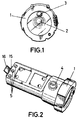
- Figure 1 shows a front view of the torch reflector in which the main and auxiliary lamps can be seen.
- Figure 2 shows a perspective view from above the torch, in which the button and charging contacts can be seen.
- Figure 3 shows a bottom perspective view showing the coupling flange and clip.
- Figure 4 is a side perspective view of the fork which is joined to the helmet.
- Figure 5 shows a perspective view of the torch with the clip inserted in the fork for coupling it to the helmet.
- Figure 6 shows a perspective view of the illumination cone coupled to the torch.
-
- The illumination devices which comprise the torch are shown in figure 1, where main lamp (2) is at the focus of the parabolic reflector, which projects a concentrated and deep beam of light. Out of the focus is an auxiliary lamp (3), which is powered and operated independently from the main one, and which projects a beam of light directed at the ground which allows the user to see the ground which is being stepped on.
- These light sources are turned on by button (4), which requires only a slight touch to be activated and which shows a large surface, thus simplifying its use.
- The effect of pressing button (4) on both lamps (2) and (3) is controlled by a programmable electronic circuit located inside the torch and powered by the same batteries, which are recharged by means of three contacts (5) shown in figure 2 with a suitable charger.
- This electronic circuit also controls the battery charging process, informs on their discharge and status, and performs automatic functions which the invention may include.
- These functions are all accessible by means of pulse sequences on button (4) and the duration of these pulses.
- The functions which the torch performs can be classified as:
- a) Manually activated
- b) Automatically activated
- c) Automatically activated information actions
- a) Manually activated functions are those related to the normal operation of
the torch regarding turning the lamps on and off and are controlled by a cycle of four
successive pulses on button (4) in the following manner:
- 1st pulse: turns on main lamp (2)
- 2nd pulse: turns off main lamp (2)
- 3rd pulse: turns on auxiliary lamp (3)
- 4th pulse: turns off auxiliary lamp (3)
- b) Functions activated automatically by the electronic circuit are meant for safety of the torch, as the object is detecting any failures in the operation of either lamp and in such event automatically activating the inactive lamp. Another automatic function performed by this circuit takes place during the battery recharging process, so that when the batteries have reached an optimum charge level the torch is automatically disconnected and placed in a maintenance charge function.
- c) Automatic information actions are meant to inform on the charge status of
the batteries, so that whenever on oef the two lamps is turned on by the pulse
sequence described above, the lamp will flash a number of times proportional to the
charge level of the batteries according to the following criteria:
- 4 flashes: 100% charged
- 3 flashes: 75% charged
- 2 flashes: 50% charged
- 1 flash: 25% charged
-
- When battery lifetime is under 10 minutes there is a warning flash every 15 seconds.
- As regards the physical means provided for coupling the torch to a helmet (13), these can be seen in figure 3, which shows flange (11) and clip (6), which consists of a flexible plate and is set so that it may swivel on hinge (15) on the rear of the torch. This hinge (15) is provided with elastic devices which make clip (6) press against the body of the torch by default, acting as a clip which can be opened manually by its projection (16).
- Clip (6) can also be used to attach the torch to the user's belt.
- As a complement of these means for coupling the torch to the helmet, on the top of the latter is placed fork (7), represented in figure 4, which consists of a bent metal part, preferably made from aluminium bronze, so that it is provided with an elasticity which makes it suitable to be used as a fork, and so that it is adapted to the surface of helmet (13).
- The disposition of fork (7) on helmet (13) can be seen in figure 5 and is achieved by means of screwing through orifices (9) on a decorative element of the helmet, so that the latter is not perforated, as otherwise it would lose its quality certification.
- In the fold of fork (7) an orifice (8) has been made in order to fully introduce clip (6) through it so that it is coupled inside fork (7), for which it is necessary to previously separate fork (6) from the body of the torch by pressing on projection (16).
- This operation is simplified by the elasticity of clip (6) and the attachment is complemented by flange (11) which is attached to recess (10) by applying a slight pressure in order to overcome the geometric relationship between both elements.
- The separation between the two plates which make up fork (7) is maintained by anchoring (12) so that coupling of clip (6) in fork (7) is favoured.
- In this manner the torch is set on the top of the helmet when so required by the user, forming a self-sufficient light source which is joined to the helmet and which frees the hands so that any task may be carried out more easily.
- All that is required in order to remove the torch from the helmet is to invert the above described process.
- Finally, and as shown in figure 6, illumination cone (14) can be attached to base (1) of the torch so that light signals can be made.
Claims (5)
- Rechargeable intelligent safety torch, particularly suited for use by fire fighters, characterised in that it is provided with the required means for attaching it to a helmet and thus, with this helmet, make up a self-sufficient light source which frees the user's hands, and in that it is provided with two independent lamps, the operation of one being automatically switched to the other in the event that one fails.
- Rechargeable intelligent safety torch, as claimed in claim 1, characterised in that the means for attaching the torch on the helmet consist of an flange on the lower face and a clip formed by a flexible plate, attached so that it may swivel to a hinge which is provided with elastic devices and which is located on the rear of the torch; and in that as a complement to these coupling means a metal part is provided on the helmet which forms a fork which is provided with orifices so that it can be attached to the helmet by screws, and in the bend of which is provided an orifice so that the clip may be fully inserted through it, which once attached remains between the two plates which form the fork, and also in that it is provided with a recess for attaching the torch flange which provides a perfect attachment.
- Rechargeable intelligent safety torch, as claimed in claim 1, characterised in that the activation and control of the lamps is carried out by means of a single high-sensitivity button by following a pulse sequence, which also allows to control all functions which the torch can perform, all of these functions being controlled by a programmable electronic circuit located inside the torch.
- Rechargeable intelligent safety torch, as claimed in claim 3, characterised in that the programmable electronic circuit allows the torch, by means of a pulse sequence, to operate in normal illumination mode, using either the main or the auxiliary lamp, or in an intermittent illumination mode, with two possible intermittence speeds.
- Rechargeable intelligent safety torch, as claimed in claims 3 and 4, characterised in that the programmable electronic circuit automatically controls the battery charging process, as well as informing the user on their charge status each time one of the lamps is turned on, by means of a number of flashes proportional to the battery status, and in that when battery lifetime is under 10 minutes a warning flash is emitted.
Applications Claiming Priority (3)
| Application Number | Priority Date | Filing Date | Title |
|---|---|---|---|
| ES9800977U ES1039829Y (en) | 1998-04-08 | 1998-04-08 | INTELLIGENT SECURITY FLASHLIGHT RECHARGEABLE. |
| ES9800977U | 1998-04-08 | ||
| PCT/ES1998/000263 WO1999053235A1 (en) | 1998-04-08 | 1998-09-25 | Rechargable security intelligent torch |
Publications (1)
| Publication Number | Publication Date |
|---|---|
| EP1069370A1 true EP1069370A1 (en) | 2001-01-17 |
Family
ID=8303736
Family Applications (1)
| Application Number | Title | Priority Date | Filing Date |
|---|---|---|---|
| EP98943899A Withdrawn EP1069370A1 (en) | 1998-04-08 | 1998-09-25 | Rechargable security intelligent torch |
Country Status (4)
| Country | Link |
|---|---|
| EP (1) | EP1069370A1 (en) |
| AU (1) | AU9162998A (en) |
| ES (1) | ES1039829Y (en) |
| WO (1) | WO1999053235A1 (en) |
Cited By (2)
| Publication number | Priority date | Publication date | Assignee | Title |
|---|---|---|---|---|
| WO2004084664A3 (en) * | 2003-03-28 | 2004-11-18 | Med Eng Systems Inc | Head protector |
| WO2006025757A1 (en) * | 2004-08-31 | 2006-03-09 | S.C. Electromax S.R.L. | Miner’s cap lamp |
Family Cites Families (7)
| Publication number | Priority date | Publication date | Assignee | Title |
|---|---|---|---|---|
| US3883777A (en) * | 1972-08-02 | 1975-05-13 | Tokai Rika Co Ltd | Device for automatically compensating failure of a lamp |
| US4225906A (en) * | 1978-03-16 | 1980-09-30 | Koehler Manufacturing Company | Luminaire apparatus with multiple light sources and methods of operating same |
| US4793007A (en) * | 1987-06-15 | 1988-12-27 | Barnett Elben R | Safety helmet and adjustable light |
| US4803605A (en) * | 1987-08-04 | 1989-02-07 | Rayovac Corporation | Flashlight with a backup system |
| US4876632A (en) * | 1988-02-10 | 1989-10-24 | Tekna, Inc. | Flashlight with battery life indicator module |
| US4998187A (en) * | 1990-02-06 | 1991-03-05 | Herrick Peter W | Headlamp holder device |
| ZA946001B (en) * | 1993-08-11 | 1996-02-12 | Designodev Ltd | Flashlight adaptor |
-
1998
- 1998-04-08 ES ES9800977U patent/ES1039829Y/en not_active Expired - Fee Related
- 1998-09-25 EP EP98943899A patent/EP1069370A1/en not_active Withdrawn
- 1998-09-25 WO PCT/ES1998/000263 patent/WO1999053235A1/en not_active Ceased
- 1998-09-25 AU AU91629/98A patent/AU9162998A/en not_active Abandoned
Non-Patent Citations (1)
| Title |
|---|
| See references of WO9953235A1 * |
Cited By (3)
| Publication number | Priority date | Publication date | Assignee | Title |
|---|---|---|---|---|
| WO2004084664A3 (en) * | 2003-03-28 | 2004-11-18 | Med Eng Systems Inc | Head protector |
| US7841026B2 (en) | 2003-03-28 | 2010-11-30 | Allen-Vanguard Technologies Inc. | Head protector |
| WO2006025757A1 (en) * | 2004-08-31 | 2006-03-09 | S.C. Electromax S.R.L. | Miner’s cap lamp |
Also Published As
| Publication number | Publication date |
|---|---|
| WO1999053235A1 (en) | 1999-10-21 |
| AU9162998A (en) | 1999-11-01 |
| ES1039829U (en) | 1999-01-16 |
| ES1039829Y (en) | 1999-07-01 |
Similar Documents
| Publication | Publication Date | Title |
|---|---|---|
| US5329637A (en) | Fireman's helmet with integral front and rear lights | |
| US10378744B2 (en) | Portable light having a forward facing light and a rearward facing light | |
| CA2759794C (en) | Shroud plate with lighting system | |
| US8292450B2 (en) | Headgear light | |
| US6250769B1 (en) | Visor light cap | |
| US5153567A (en) | Alarm kit apparatus | |
| US20100287676A1 (en) | Welding mask | |
| US20100313328A1 (en) | Lighted safety apparel and method | |
| US20030206410A1 (en) | Dual mode rechargeable flashlight | |
| US20060202629A1 (en) | Three component protective head gear powered by a rechargeable battery | |
| GB2457313A (en) | Processor controlled identifying light | |
| US7075250B2 (en) | Three-component protective head gear powered by a rechargeable battery | |
| CA3092755C (en) | Auto-darkening welding helmet | |
| US11925229B2 (en) | Safety helmet to be used by a person in low light conditions and monitoring procedure associated | |
| EP1069370A1 (en) | Rechargable security intelligent torch | |
| GB2107039A (en) | Protective headwear | |
| JPH087602A (en) | Flashlight with sos buzzer | |
| CN213118544U (en) | Multifunctional intelligent voice acousto-optic alarm flashlight | |
| CN207514630U (en) | A kind of fire-fighting LED light | |
| US4481560A (en) | Safety lamp with noctilucent lens holder | |
| CN107830428B (en) | Fire-fighting LED lamp | |
| CN108716641B (en) | Light control assembly and ignition gun | |
| WO2005069240A3 (en) | Fire detector | |
| KR200265902Y1 (en) | Rechargeable Helmet And Rack | |
| KR200320716Y1 (en) | Shoes with built-in luminescence and talk |
Legal Events
| Date | Code | Title | Description |
|---|---|---|---|
| PUAI | Public reference made under article 153(3) epc to a published international application that has entered the european phase |
Free format text: ORIGINAL CODE: 0009012 |
|
| 17P | Request for examination filed |
Effective date: 20001108 |
|
| AK | Designated contracting states |
Kind code of ref document: A1 Designated state(s): AT BE CH DE DK FI FR GB GR IE IT LI NL PT SE |
|
| RAP1 | Party data changed (applicant data changed or rights of an application transferred) |
Owner name: ADARO TECNOLOGIA, S.A. |
|
| STAA | Information on the status of an ep patent application or granted ep patent |
Free format text: STATUS: THE APPLICATION IS DEEMED TO BE WITHDRAWN |
|
| 18D | Application deemed to be withdrawn |
Effective date: 20040331 |