EP1069357A2 - Dispositif de commande pour vanne électromagnétique - Google Patents
Dispositif de commande pour vanne électromagnétique Download PDFInfo
- Publication number
- EP1069357A2 EP1069357A2 EP00114373A EP00114373A EP1069357A2 EP 1069357 A2 EP1069357 A2 EP 1069357A2 EP 00114373 A EP00114373 A EP 00114373A EP 00114373 A EP00114373 A EP 00114373A EP 1069357 A2 EP1069357 A2 EP 1069357A2
- Authority
- EP
- European Patent Office
- Prior art keywords
- magnetic
- armature
- magnet armature
- magnet
- actuator according
- Prior art date
- Legal status (The legal status is an assumption and is not a legal conclusion. Google has not performed a legal analysis and makes no representation as to the accuracy of the status listed.)
- Withdrawn
Links
- 230000005291 magnetic effect Effects 0.000 claims abstract description 178
- 230000009471 action Effects 0.000 claims abstract description 4
- 230000000694 effects Effects 0.000 claims abstract description 4
- 239000000696 magnetic material Substances 0.000 claims description 5
- 238000004804 winding Methods 0.000 claims description 5
- 230000000181 anti-adherent effect Effects 0.000 claims description 4
- 125000006850 spacer group Chemical group 0.000 claims description 3
- 239000007789 gas Substances 0.000 description 10
- 239000003302 ferromagnetic material Substances 0.000 description 5
- 101100390736 Danio rerio fign gene Proteins 0.000 description 2
- 101100390738 Mus musculus Fign gene Proteins 0.000 description 2
- 230000005294 ferromagnetic effect Effects 0.000 description 2
- 239000011248 coating agent Substances 0.000 description 1
- 238000000576 coating method Methods 0.000 description 1
- 238000009826 distribution Methods 0.000 description 1
- 230000004907 flux Effects 0.000 description 1
- 239000007788 liquid Substances 0.000 description 1
- 238000004519 manufacturing process Methods 0.000 description 1
- 230000004048 modification Effects 0.000 description 1
- 238000012986 modification Methods 0.000 description 1
- 230000000149 penetrating effect Effects 0.000 description 1
- 239000004810 polytetrafluoroethylene Substances 0.000 description 1
- 229920001343 polytetrafluoroethylene Polymers 0.000 description 1
- 230000001105 regulatory effect Effects 0.000 description 1
Images

Classifications
-
- F—MECHANICAL ENGINEERING; LIGHTING; HEATING; WEAPONS; BLASTING
- F16—ENGINEERING ELEMENTS AND UNITS; GENERAL MEASURES FOR PRODUCING AND MAINTAINING EFFECTIVE FUNCTIONING OF MACHINES OR INSTALLATIONS; THERMAL INSULATION IN GENERAL
- F16K—VALVES; TAPS; COCKS; ACTUATING-FLOATS; DEVICES FOR VENTING OR AERATING
- F16K31/00—Actuating devices; Operating means; Releasing devices
- F16K31/02—Actuating devices; Operating means; Releasing devices electric; magnetic
- F16K31/06—Actuating devices; Operating means; Releasing devices electric; magnetic using a magnet, e.g. diaphragm valves, cutting off by means of a liquid
- F16K31/0603—Multiple-way valves
- F16K31/0624—Lift valves
-
- F—MECHANICAL ENGINEERING; LIGHTING; HEATING; WEAPONS; BLASTING
- F16—ENGINEERING ELEMENTS AND UNITS; GENERAL MEASURES FOR PRODUCING AND MAINTAINING EFFECTIVE FUNCTIONING OF MACHINES OR INSTALLATIONS; THERMAL INSULATION IN GENERAL
- F16K—VALVES; TAPS; COCKS; ACTUATING-FLOATS; DEVICES FOR VENTING OR AERATING
- F16K1/00—Lift valves or globe valves, i.e. cut-off apparatus with closure members having at least a component of their opening and closing motion perpendicular to the closing faces
- F16K1/32—Details
- F16K1/34—Cutting-off parts, e.g. valve members, seats
- F16K1/44—Details of seats or valve members of double-seat valves
- F16K1/443—Details of seats or valve members of double-seat valves the seats being in series
-
- F—MECHANICAL ENGINEERING; LIGHTING; HEATING; WEAPONS; BLASTING
- F16—ENGINEERING ELEMENTS AND UNITS; GENERAL MEASURES FOR PRODUCING AND MAINTAINING EFFECTIVE FUNCTIONING OF MACHINES OR INSTALLATIONS; THERMAL INSULATION IN GENERAL
- F16K—VALVES; TAPS; COCKS; ACTUATING-FLOATS; DEVICES FOR VENTING OR AERATING
- F16K31/00—Actuating devices; Operating means; Releasing devices
- F16K31/02—Actuating devices; Operating means; Releasing devices electric; magnetic
- F16K31/06—Actuating devices; Operating means; Releasing devices electric; magnetic using a magnet, e.g. diaphragm valves, cutting off by means of a liquid
- F16K31/0603—Multiple-way valves
- F16K31/0624—Lift valves
- F16K31/0627—Lift valves with movable valve member positioned between seats
-
- F—MECHANICAL ENGINEERING; LIGHTING; HEATING; WEAPONS; BLASTING
- F16—ENGINEERING ELEMENTS AND UNITS; GENERAL MEASURES FOR PRODUCING AND MAINTAINING EFFECTIVE FUNCTIONING OF MACHINES OR INSTALLATIONS; THERMAL INSULATION IN GENERAL
- F16K—VALVES; TAPS; COCKS; ACTUATING-FLOATS; DEVICES FOR VENTING OR AERATING
- F16K31/00—Actuating devices; Operating means; Releasing devices
- F16K31/02—Actuating devices; Operating means; Releasing devices electric; magnetic
- F16K31/06—Actuating devices; Operating means; Releasing devices electric; magnetic using a magnet, e.g. diaphragm valves, cutting off by means of a liquid
- F16K31/0644—One-way valve
- F16K31/0655—Lift valves
-
- H—ELECTRICITY
- H01—ELECTRIC ELEMENTS
- H01F—MAGNETS; INDUCTANCES; TRANSFORMERS; SELECTION OF MATERIALS FOR THEIR MAGNETIC PROPERTIES
- H01F7/00—Magnets
- H01F7/06—Electromagnets; Actuators including electromagnets
- H01F7/08—Electromagnets; Actuators including electromagnets with armatures
- H01F7/081—Magnetic constructions
-
- H—ELECTRICITY
- H01—ELECTRIC ELEMENTS
- H01F—MAGNETS; INDUCTANCES; TRANSFORMERS; SELECTION OF MATERIALS FOR THEIR MAGNETIC PROPERTIES
- H01F7/00—Magnets
- H01F7/06—Electromagnets; Actuators including electromagnets
- H01F7/08—Electromagnets; Actuators including electromagnets with armatures
- H01F7/16—Rectilinearly-movable armatures
- H01F7/1607—Armatures entering the winding
Definitions
- the invention relates to a magnetic actuator for two actuators, one against the action of a restoring force axially displaceable outer magnet armature for actuation one control element and one against the effect a restoring force axially displaceable inner magnet armature to actuate the other actuator, the inner Magnetic anchor can be moved longitudinally in the outer magnetic anchor protrudes with a magnetic drive into which both magnet anchors protrude into it, and with one on the outer magnet armature attached inner magnetic closure body for the inner magnet armature, and a corresponding solenoid valve.
- Such a magnetic actuator is for example for a double safety valve by DE 195 25 384 A1 known.
- the two magnetic armatures are one inside the other arranged that the outer armature at the same time for the inner magnet armature forms a magnetic closure body. This causes the two magnet anchors to be more constructive Interpretation, simultaneously or one after the other, in opposite directions Move direction.
- the two magnetic circuits for the inner and outer magnetic anchors can be designed that due to different magnetically conductive cross sections and different restoring forces the two Magnetic armature can be operated simultaneously or in succession.
- the invention enables a magnetic actuator with two counter-acting anchors, especially for actuation of two actuators with different functions.
- two magnet armatures arranged coaxially to each other, because so the magnetic actuator is particularly compact and Space-saving design and thus inexpensive to manufacture.
- the inner magnet armature axially spaced from the inner magnetic closure body has the consequence that first the outer magnet armature is tightened and only when the inner magnetic closure body pulled close to the inner magnet armature the inner magnetic armature was also moving. This means, the two magnetic anchors are successively in opposite directions Direction attracted.
- the external magnet armature is not tightened, the inner magnetic armature already in the inner magnetic closing body protrudes axially, is the magnetic circuit through the inner magnet armature closed, so that the inner and outer magnet armature attracted simultaneously in opposite directions become.
- the magnetically effective for the inner magnet armature Cross-section of the inner magnetic closure body in its tightening direction ensures that the force acting on the inner magnet armature with the Tightening distance of the outer magnet armature increased.
- the inner magnetic closure body is preferably in the form of a magnetic closure sleeve trained in the opening of the tightened inner Magnetic armature protrudes.
- the one facing the inner magnet armature The end of the magnetic closure sleeve can be on the outside Be tapered towards the inner magnet armature, causing the magnetic resistance between the inner armature and magnetic closure sleeve with the tightening path of the outer Magnetic armature is reduced.
- the two can Magnetic armature can be actuated in a targeted manner.
- the magnetic drive comprises a magnetic coil with two electrically separate windings, which lead to different sized magnetic fields, when it is energized independently become.
- an electronic switching device for the Supply voltage and / or current of the magnetic drive provided with which the magnetic force of the magnetic drive for actuation of the outer magnet armature and for an additional one Operation of the inner armature set can be.
- the inner magnetic closure body on the outer magnet armature by a separate one axial connecting element attached e.g. as a den thin-walled tube surrounding the inner magnet armature is.
- the connector should be made of non-magnetic material be made to the magnetic field of the magnetic drive not to be influenced.
- a two or three is for the outer armature multi-part outer magnetic closure sleeve provided, into the the outer magnet armature is tightened.
- the outer magnetic closure sleeve can radially within a magnetic coil of the Magnet drive and be arranged from a magnetic Upper part and magnetic lower part exist in the axial Are spaced from each other. Between the upper and lower part can be provided a non-magnetic middle part his. With such a 2 or 3-stage magnetic closure sleeve can be particularly cheap magnetic Generate force line distributions in the magnetic drive.
- a non-stick disc provided, preferably made of non-magnetic Material is made. This is a "sticking" of the inner magnet armature on the inner magnetic closure body or of the outer magnet armature on its pole system after switching off of the magnetic drive through magnetic remanence in the respective Prevents sharing.
- the invention also relates to a solenoid valve with a like trained magnetic actuator described above, whose first valve plate with the outer magnet armature and its second valve plate with the inner magnet armature are motion-coupled.
- Two drives can be in the solenoid valve according to the invention for two actuators with different functions.
- the solenoid valve can e.g. as a two-stage valve for primarily low operating pressures or as a valve with integrated electrical proportional control his.
- the double solenoid valve also makes it possible in one Housing both a shut-off valve and a leak gas valve to integrate with a common drive.
- the first valve disk is preferably on the inner magnetic closure body provided and the second valve plate through the inner magnetic closure body through the inner magnet armature attached.
- the latter connection can e.g. by a rod formed through the inner magnetic closure body be the inner armature and the second valve plate rigidly connected.
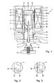
- Fig. 1 denotes the drive of a solenoid valve
- the two series-connected valves 2 and 3 have a common valve opening 4 and are arranged coaxially to one another.
- the first valve 2 comprises a first valve plate 5 , a first closing spring 6 and, as an actuator for the first valve plate 5, an outer magnet armature 7 made of ferromagnetic material.
- the valve seat for the first valve plate 5 is located on the top of the valve opening wall 8.
- the second valve 3 comprises a second valve plate 9 , a second closing spring 10 and, as an actuator for the second valve plate 9, an inner magnet armature 11 made of ferromagnetic material.
- the valve seat for the second valve plate 9 is located on the underside of the valve opening wall 8.
- a common magnetic drive 12 which essentially consists of a magnet housing 13 , a yoke 14 , a magnet coil 15 and an outer magnetic closure sleeve 16 arranged therein.
- This magnetic closure sleeve 16 is formed in two parts from an approximately cup-shaped ferromagnetic upper part 17 and a tubular ferromagnetic lower part 18 , the two parts 17, 18 being axially spaced apart from one another by means of a thin-walled tube 19 made of non-ferromagnetic material.
- an inner magnetic closure body 20 made of ferromagnetic material is axially spaced and motionally coupled via a rigid connecting element 21 .
- the connecting element 21 is a thin-walled tube which is fastened on the outside to the two parts 7 and 20.
- a first valve disk 5 is provided on the inner magnetic closure body 20.
- the outer magnet armature 7 and the inner magnetic closing body 20 are guided axially displaceably in the magnetic closing sleeve 16.
- the first closing spring 6 is supported between the first valve plate 5 and the lower part 18, while the second closing spring 10 is supported between the second valve plate 9 and the valve housing 22 .
- the inner magnet armature 11 projects into the outer magnet armature 7 and is guided axially displaceably therein.
- the second valve disk 9 is rigidly connected to the inner magnet armature 11 via a rod 23 penetrating the inner magnetic closure body 20, two guide sleeves 24 being provided for the rod 23.
- the guide surfaces of the inner magnetic closure body 20 can also be provided with a low-friction coating (for example PTFE).
- a spacer 25 made of non-ferromagnetic material is arranged between them. Sticking of the two magnetic armatures 7, 11 after the magnetic field of the magnetic coil 15 has dropped is prevented by an anti-adhesive disk 26 , 27 between the outer magnetic armature 11 and the upper part 17 or between the inner magnetic armature 11 and the inner magnetic closing body 20.
- the double solenoid valve 1 in one Both can be used for control devices for gases or liquids Parts 17, 18 of the magnetic closure sleeve 16 and the outer magnet armature 7 and the magnetic closure body 20 by means of the tube 19 or the connecting element 21 are tightly connected to one another his.
- the inner magnet armature 11 is axially spaced from the inner magnet closing body 20 when the magnet coil 15 is not energized.
- an annular control edge 28 is provided on the inner magnetic closure body 20, which tapers conically on the outside in the direction of the inner magnet armature 11. This control edge 28 has the effect that the magnetic resistance effective between the inner magnet armature 11 and the inner magnet closure body 20 is reduced when the inner magnet armature 11 projects into the opening 29 of the inner magnet closure body 20.
- the inner magnet armature 11 already protrudes somewhat into the opening 29 'of the inner magnetic closing body 20' when the magnet coil 15 is not energized, since the control edge 28 ' is formed higher here than in FIG. 2.
- the inner magnet armature 11 can be axially displaced to the same extent in the direction of the inner magnet closing body 20.
- FIG. 4 the operation of the in Figs. 1 and 2 shown solenoid valve 1:
- a magnetic field is generated, which is transmitted to the outer magnet armature 7 via the control edge 30 , (FIG. 1) on the upper and lower part 17, 18 of the magnet closure sleeve 16.
- a closed first magnetic circuit 32 is formed via the yoke 14, the upper part 17, the outer magnet armature 7 and the lower part 18.
- the magnetic circuit 32 is designed so that the lines of force initially flow through the upper part 17 into the outer magnet armature 7 and via this into the lower part of the magnet sleeve 18 when the coil 15 is excited.
- the two magnetic circuits 32, 35 can also be designed that due to different magnetically conductive Cross sections and different closing springs 6, 10 die two magnet armatures 7, 11 are activated simultaneously. So 3 move the two Magnet armature 7, 11, since the second magnetic circuit when not attracted outer magnet armature 7 through the inner magnetic closure body 20 'is already closed, simultaneously in opposite directions. The two valves 2, 3 are open at the same time.
- the two magnet armatures 7, 11 can also use the magnetic field can be controlled in sequence, e.g. by the supply voltage the magnet coil 15 is varied. That is because of the solenoid 15 no voltage (0 volts), the solenoid valve closed (Fig. 4a). At a tension of e.g. 110 volts, the first valve 2 is already fully open, while the second valve 3 continues to close is (Fig. 4b). Only at higher voltages (e.g. 150 volts), the magnetic field is then sufficient around the inner magnet armature 11 and thus also the second valve 3 to open. At a voltage of e.g. Then is 220 volts also the second valve 3 fully opened (Fig. 4c).
- the inner magnet armature 11 or that open the second valve 3 proportional to the coil voltage With a suitable design of those determining the second magnetic circuit Parameters, e.g. the control edge 28 of the magnetic closing body 20, the inner magnet armature 11 or that open the second valve 3 proportional to the coil voltage.
- the solenoid valve can be controlled with only two voltages (e.g. 110 volts and 220 volts) also as two-stage Valve, especially for low operating pressures become.
- Two different sized magnetic fields can also be by a magnetic coil 15 with two superimposed Generate windings by initially only one winding to actuate the outer armature 7 and then the other winding for actuating the inner magnet armature 7 is energized.
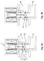
- FIG. 5 shows an application of the double solenoid valve 1 as a gas solenoid valve with an integrated leakage gas valve 38 .
- the amount of gas flowing from a gas inlet chamber 39 through the valve opening 4 into a gas outlet chamber 40 is regulated by the two valves 2, 3.
- the second valve plate 9 closes in its fully open position (FIG. 5b) a further valve opening 41 , which otherwise connects the gas outlet space 40 to a leakage discharge line 42 (FIG. 5a).
Landscapes
- Engineering & Computer Science (AREA)
- General Engineering & Computer Science (AREA)
- Mechanical Engineering (AREA)
- Physics & Mathematics (AREA)
- Electromagnetism (AREA)
- Power Engineering (AREA)
- Magnetically Actuated Valves (AREA)
Applications Claiming Priority (2)
| Application Number | Priority Date | Filing Date | Title |
|---|---|---|---|
| DE19933329 | 1999-07-16 | ||
| DE1999133329 DE19933329C1 (de) | 1999-07-16 | 1999-07-16 | Magnetische Stellvorrichtung für ein Magnetventil |
Publications (2)
| Publication Number | Publication Date |
|---|---|
| EP1069357A2 true EP1069357A2 (fr) | 2001-01-17 |
| EP1069357A3 EP1069357A3 (fr) | 2002-07-24 |
Family
ID=7914978
Family Applications (1)
| Application Number | Title | Priority Date | Filing Date |
|---|---|---|---|
| EP00114373A Withdrawn EP1069357A3 (fr) | 1999-07-16 | 2000-07-05 | Dispositif de commande pour vanne électromagnétique |
Country Status (2)
| Country | Link |
|---|---|
| EP (1) | EP1069357A3 (fr) |
| DE (1) | DE19933329C1 (fr) |
Cited By (16)
| Publication number | Priority date | Publication date | Assignee | Title |
|---|---|---|---|---|
| US9074770B2 (en) | 2011-12-15 | 2015-07-07 | Honeywell International Inc. | Gas valve with electronic valve proving system |
| US9645584B2 (en) | 2014-09-17 | 2017-05-09 | Honeywell International Inc. | Gas valve with electronic health monitoring |
| US9657946B2 (en) | 2012-09-15 | 2017-05-23 | Honeywell International Inc. | Burner control system |
| US9683674B2 (en) | 2013-10-29 | 2017-06-20 | Honeywell Technologies Sarl | Regulating device |
| US9835265B2 (en) | 2011-12-15 | 2017-12-05 | Honeywell International Inc. | Valve with actuator diagnostics |
| US9841122B2 (en) | 2014-09-09 | 2017-12-12 | Honeywell International Inc. | Gas valve with electronic valve proving system |
| US9846440B2 (en) | 2011-12-15 | 2017-12-19 | Honeywell International Inc. | Valve controller configured to estimate fuel comsumption |
| US9851103B2 (en) | 2011-12-15 | 2017-12-26 | Honeywell International Inc. | Gas valve with overpressure diagnostics |
| US9995486B2 (en) | 2011-12-15 | 2018-06-12 | Honeywell International Inc. | Gas valve with high/low gas pressure detection |
| US10024439B2 (en) | 2013-12-16 | 2018-07-17 | Honeywell International Inc. | Valve over-travel mechanism |
| US10422531B2 (en) | 2012-09-15 | 2019-09-24 | Honeywell International Inc. | System and approach for controlling a combustion chamber |
| US10503181B2 (en) | 2016-01-13 | 2019-12-10 | Honeywell International Inc. | Pressure regulator |
| US10564062B2 (en) | 2016-10-19 | 2020-02-18 | Honeywell International Inc. | Human-machine interface for gas valve |
| US10697815B2 (en) | 2018-06-09 | 2020-06-30 | Honeywell International Inc. | System and methods for mitigating condensation in a sensor module |
| US10697632B2 (en) | 2011-12-15 | 2020-06-30 | Honeywell International Inc. | Gas valve with communication link |
| US11073281B2 (en) | 2017-12-29 | 2021-07-27 | Honeywell International Inc. | Closed-loop programming and control of a combustion appliance |
Families Citing this family (10)
| Publication number | Priority date | Publication date | Assignee | Title |
|---|---|---|---|---|
| US6669166B2 (en) * | 2000-07-28 | 2003-12-30 | Nippon Soken, Inc. | Electromagnetic valve |
| DE10248143B4 (de) * | 2002-10-16 | 2004-12-09 | Kuhnke Gmbh | Bistabiler Doppelanker-Hubmagnet |
| DE10361918B4 (de) * | 2003-12-23 | 2006-10-12 | Saia-Burgess Dresden Gmbh | Gasregel- und Sicherheitsventil |
| DE102004004708B3 (de) | 2004-01-30 | 2005-04-21 | Karl Dungs Gmbh & Co. Kg | Magnetventil |
| US8905063B2 (en) | 2011-12-15 | 2014-12-09 | Honeywell International Inc. | Gas valve with fuel rate monitor |
| US8839815B2 (en) | 2011-12-15 | 2014-09-23 | Honeywell International Inc. | Gas valve with electronic cycle counter |
| US8947242B2 (en) | 2011-12-15 | 2015-02-03 | Honeywell International Inc. | Gas valve with valve leakage test |
| US8899264B2 (en) | 2011-12-15 | 2014-12-02 | Honeywell International Inc. | Gas valve with electronic proof of closure system |
| DE102014003381A1 (de) | 2014-03-06 | 2015-09-10 | Wabco Gmbh | Magnetventil |
| DE102018132442B4 (de) * | 2018-12-17 | 2020-07-30 | Samson Aktiengesellschaft | Elektropneumatisches Magnetventil, Feldgerät mit einem Magnetventil und Diagnoseverfahren für ein elektropneumatisches Magnetventil |
Citations (1)
| Publication number | Priority date | Publication date | Assignee | Title |
|---|---|---|---|---|
| DE19525384A1 (de) | 1995-07-12 | 1997-01-16 | Dungs Karl Gmbh & Co | Doppel-Sicherheitsmagnetventil |
Family Cites Families (1)
| Publication number | Priority date | Publication date | Assignee | Title |
|---|---|---|---|---|
| DE19751240A1 (de) * | 1997-11-19 | 1999-05-20 | Itt Mfg Enterprises Inc | Elektromagnetventil |
-
1999
- 1999-07-16 DE DE1999133329 patent/DE19933329C1/de not_active Expired - Fee Related
-
2000
- 2000-07-05 EP EP00114373A patent/EP1069357A3/fr not_active Withdrawn
Patent Citations (1)
| Publication number | Priority date | Publication date | Assignee | Title |
|---|---|---|---|---|
| DE19525384A1 (de) | 1995-07-12 | 1997-01-16 | Dungs Karl Gmbh & Co | Doppel-Sicherheitsmagnetventil |
Cited By (20)
| Publication number | Priority date | Publication date | Assignee | Title |
|---|---|---|---|---|
| US9074770B2 (en) | 2011-12-15 | 2015-07-07 | Honeywell International Inc. | Gas valve with electronic valve proving system |
| US10697632B2 (en) | 2011-12-15 | 2020-06-30 | Honeywell International Inc. | Gas valve with communication link |
| US9835265B2 (en) | 2011-12-15 | 2017-12-05 | Honeywell International Inc. | Valve with actuator diagnostics |
| US10851993B2 (en) | 2011-12-15 | 2020-12-01 | Honeywell International Inc. | Gas valve with overpressure diagnostics |
| US9846440B2 (en) | 2011-12-15 | 2017-12-19 | Honeywell International Inc. | Valve controller configured to estimate fuel comsumption |
| US9851103B2 (en) | 2011-12-15 | 2017-12-26 | Honeywell International Inc. | Gas valve with overpressure diagnostics |
| US9995486B2 (en) | 2011-12-15 | 2018-06-12 | Honeywell International Inc. | Gas valve with high/low gas pressure detection |
| US11421875B2 (en) | 2012-09-15 | 2022-08-23 | Honeywell International Inc. | Burner control system |
| US9657946B2 (en) | 2012-09-15 | 2017-05-23 | Honeywell International Inc. | Burner control system |
| US10422531B2 (en) | 2012-09-15 | 2019-09-24 | Honeywell International Inc. | System and approach for controlling a combustion chamber |
| US9683674B2 (en) | 2013-10-29 | 2017-06-20 | Honeywell Technologies Sarl | Regulating device |
| US10215291B2 (en) | 2013-10-29 | 2019-02-26 | Honeywell International Inc. | Regulating device |
| US10024439B2 (en) | 2013-12-16 | 2018-07-17 | Honeywell International Inc. | Valve over-travel mechanism |
| US9841122B2 (en) | 2014-09-09 | 2017-12-12 | Honeywell International Inc. | Gas valve with electronic valve proving system |
| US10203049B2 (en) | 2014-09-17 | 2019-02-12 | Honeywell International Inc. | Gas valve with electronic health monitoring |
| US9645584B2 (en) | 2014-09-17 | 2017-05-09 | Honeywell International Inc. | Gas valve with electronic health monitoring |
| US10503181B2 (en) | 2016-01-13 | 2019-12-10 | Honeywell International Inc. | Pressure regulator |
| US10564062B2 (en) | 2016-10-19 | 2020-02-18 | Honeywell International Inc. | Human-machine interface for gas valve |
| US11073281B2 (en) | 2017-12-29 | 2021-07-27 | Honeywell International Inc. | Closed-loop programming and control of a combustion appliance |
| US10697815B2 (en) | 2018-06-09 | 2020-06-30 | Honeywell International Inc. | System and methods for mitigating condensation in a sensor module |
Also Published As
| Publication number | Publication date |
|---|---|
| DE19933329C1 (de) | 2000-06-21 |
| EP1069357A3 (fr) | 2002-07-24 |
Similar Documents
| Publication | Publication Date | Title |
|---|---|---|
| DE19933329C1 (de) | Magnetische Stellvorrichtung für ein Magnetventil | |
| DE19826076C1 (de) | Doppelsicherheitsventil | |
| DE3802648C2 (fr) | ||
| EP2250651B1 (fr) | Dispositif électromagnétique de positionnement | |
| DE102004004708B3 (de) | Magnetventil | |
| DE69004845T2 (de) | Elektromagnetisches Ventil mit Verwendung eines permanenten Magneten. | |
| EP0197356B1 (fr) | Dispositif de réglage électromagnétique | |
| DE19655090C2 (de) | Elektromagnetisch betätigtes Wegeventil | |
| EP1959178B1 (fr) | Soupape devant être actionnée de manière électromagnétique | |
| DE4012832C2 (de) | Magnetventil | |
| DE102011002544A1 (de) | Magnetventil sowie Verfahren zum Betreiben des Magnetventils | |
| DE602004006563T2 (de) | Magnetischer Betätiger | |
| DE102015111561B4 (de) | Elektromagnetisch betätigtes schaltventil | |
| EP3008366A1 (fr) | Électrovanne de réglage de débit d'un fluide sous pression | |
| DE102007005916A1 (de) | Doppelankermagnetventil mit zwei Ventilöffnungen und mindestens einem die Ventilöffnungen verbindenden Kanal | |
| DE2261278A1 (de) | Doppelventil | |
| DE4439695C2 (de) | Magnetventil und dessen Verwendung | |
| DE10327209B3 (de) | Schaltvorrichtung, insbesondere zum Betätigen von Ventilen | |
| EP1620667B1 (fr) | Dispositif electro-aimant de levage | |
| DE60314359T2 (de) | Elekromagnetisches Kraftstoffeinspritzventil mit einem monolithischen rohrförmigen Element für eine Brennkraftmaschine | |
| DE19502671A1 (de) | Elektromagnetantrieb, insbesondere für Elektromagnetventile als Stellglieder für Fluide | |
| DE4020164A1 (de) | Elektromagnetisch betaetigtes ventil | |
| EP0859380B1 (fr) | Electro-aimant de commande à double effet | |
| DE29912431U1 (de) | Magnetische Stellvorrichtung für ein Magnetventil | |
| DE4109377C1 (en) | Variable shock absorber for motor vehicle - uses three=way of by=pass of hydraulic cylinder chamber divided in two by damping piston |
Legal Events
| Date | Code | Title | Description |
|---|---|---|---|
| PUAI | Public reference made under article 153(3) epc to a published international application that has entered the european phase |
Free format text: ORIGINAL CODE: 0009012 |
|
| AK | Designated contracting states |
Kind code of ref document: A2 Designated state(s): AT BE CH CY DE DK ES FI FR GB GR IE IT LI LU MC NL PT SE |
|
| AX | Request for extension of the european patent |
Free format text: AL;LT;LV;MK;RO;SI |
|
| PUAL | Search report despatched |
Free format text: ORIGINAL CODE: 0009013 |
|
| AK | Designated contracting states |
Kind code of ref document: A3 Designated state(s): AT BE CH CY DE DK ES FI FR GB GR IE IT LI LU MC NL PT SE |
|
| AX | Request for extension of the european patent |
Free format text: AL;LT;LV;MK;RO;SI |
|
| 17P | Request for examination filed |
Effective date: 20021018 |
|
| AKX | Designation fees paid |
Designated state(s): DE FR GB IT |
|
| STAA | Information on the status of an ep patent application or granted ep patent |
Free format text: STATUS: THE APPLICATION IS DEEMED TO BE WITHDRAWN |
|
| 18D | Application deemed to be withdrawn |
Effective date: 20040203 |