EP1069345A2 - Mechanical-hydrostatic transmission, particularly for agricultural vehicles such as lawn-mowers or the like - Google Patents
Mechanical-hydrostatic transmission, particularly for agricultural vehicles such as lawn-mowers or the like Download PDFInfo
- Publication number
- EP1069345A2 EP1069345A2 EP00114127A EP00114127A EP1069345A2 EP 1069345 A2 EP1069345 A2 EP 1069345A2 EP 00114127 A EP00114127 A EP 00114127A EP 00114127 A EP00114127 A EP 00114127A EP 1069345 A2 EP1069345 A2 EP 1069345A2
- Authority
- EP
- European Patent Office
- Prior art keywords
- pump
- shaft
- hydraulic motor
- transmission according
- casing
- Prior art date
- Legal status (The legal status is an assumption and is not a legal conclusion. Google has not performed a legal analysis and makes no representation as to the accuracy of the status listed.)
- Withdrawn
Links
- 230000005540 biological transmission Effects 0.000 title claims abstract description 32
- 230000009467 reduction Effects 0.000 claims abstract description 15
- 238000010413 gardening Methods 0.000 claims abstract description 8
- 230000008878 coupling Effects 0.000 claims abstract description 4
- 238000010168 coupling process Methods 0.000 claims abstract description 4
- 238000005859 coupling reaction Methods 0.000 claims abstract description 4
- 238000006073 displacement reaction Methods 0.000 claims description 4
- 238000004519 manufacturing process Methods 0.000 description 4
- 230000009347 mechanical transmission Effects 0.000 description 4
- 230000002706 hydrostatic effect Effects 0.000 description 1
- 230000010354 integration Effects 0.000 description 1
- 230000000670 limiting effect Effects 0.000 description 1
- 230000004048 modification Effects 0.000 description 1
- 238000012986 modification Methods 0.000 description 1
Images

Classifications
-
- F—MECHANICAL ENGINEERING; LIGHTING; HEATING; WEAPONS; BLASTING
- F16—ENGINEERING ELEMENTS AND UNITS; GENERAL MEASURES FOR PRODUCING AND MAINTAINING EFFECTIVE FUNCTIONING OF MACHINES OR INSTALLATIONS; THERMAL INSULATION IN GENERAL
- F16H—GEARING
- F16H47/00—Combinations of mechanical gearing with fluid clutches or fluid gearing
- F16H47/02—Combinations of mechanical gearing with fluid clutches or fluid gearing the fluid gearing being of the volumetric type
-
- Y—GENERAL TAGGING OF NEW TECHNOLOGICAL DEVELOPMENTS; GENERAL TAGGING OF CROSS-SECTIONAL TECHNOLOGIES SPANNING OVER SEVERAL SECTIONS OF THE IPC; TECHNICAL SUBJECTS COVERED BY FORMER USPC CROSS-REFERENCE ART COLLECTIONS [XRACs] AND DIGESTS
- Y10—TECHNICAL SUBJECTS COVERED BY FORMER USPC
- Y10T—TECHNICAL SUBJECTS COVERED BY FORMER US CLASSIFICATION
- Y10T74/00—Machine element or mechanism
- Y10T74/19—Gearing
- Y10T74/19149—Gearing with fluid drive
Definitions
- the present invention relates to a mechanical-hydrostatic transmission, particularly for tools and vehicles suitable for gardening, such as lawn-mowers or the like.
- Such vehicles are usually provided with an engine which requires a mechanical transmission for moving the driving wheels.
- mechanical transmissions for such vehicles comprise a reduction unit, a clutch unit arranged within a casing and, associated with said casing, auxiliary casings which accommodate an oil pump and a hydraulic motor which are adapted to operate in connection with said clutch unit.
- the aim of the present invention is to provide a mechanical-hydrostatic transmission, particularly for tools and vehicles suitable for gardening, such as lawn-mowers or the like, which solves the above-noted drawbacks of conventional transmissions, particularly achieving considerable structural simplification, improving both the manufacture of the transmission and its sturdiness and operating functionality during use.
- an object of the present invention is to provide a mechanical-hydrostatic transmission which allows a numerically large component reduction, with a consequent production cost reduction without however impairing operating functionality.
- Another object of the present invention is to provide a mechanical-hydrostatic transmission which has a wide adjustment range and reduction variability and therefore does not require additional auxiliary reduction units arranged downstream of it.
- Another object of the present invention is to provide a mechanical-hydrostatic transmission which requires a hydraulic circuit system which is simple and at the same time highly functional and safe, owing to the smaller number of components at risk of failure.
- Another object of the present invention is to provide a mechanical-hydrostatic transmission which is functionally flexible with respect to the most disparate requirements of the application and of the vehicle on which it can be installed.
- a mechanical-hydrostatic transmission particularly for tools and vehicles suitable for gardening, such as lawn-mowers or the like, characterized in that it comprises a reduction unit, a clutch unit, an oil pump and a hydraulic motor which are integrated and contained within a single casing, said pump and said clutch unit being arranged coaxially on a first shaft which is connected externally, by means of a coupling, to motor means, said pump being hydraulically connected to said hydraulic motor and said hydraulic motor being in turn axially associated with a second shaft from which a power take-off extends, said casing containing kinematic connections for transmitting motion to the driving wheels.
- a mechanical-hydrostatic transmission particularly for tools and vehicles suitable for gardening, such as lawn-mowers or the like, according to the invention, is generally designated by the reference numeral 10.
- the transmission 10 is applied in this case to a compact tractor, generally designated by the reference numeral 11, which is outfitted as a lawn-mower.
- the transmission 10 comprises a reduction unit 13, a clutch unit 14, an oil pump 15 and a hydraulic motor 16, which are integrated and contained within a single casing 12 with a cover 32.
- the pump 15 and the clutch unit 14 are arranged coaxially on a first shaft 17 which is connected externally, by means of a coupling 18, to motor means generally designated by the reference numeral 19.
- the pump 15 is hydraulically connected to the hydraulic motor 16 and the motor is axially associated with a second shaft 20 which is coaxially connected to a third shaft 21 which protrudes from the casing 12 so as to form a power take-off 22.
- the casing 12 also contains kinematic connections, generally designated by the reference numeral 23, for the axles of the driving wheels, respectively designated by the reference numerals 24 and 25.
- the oil pump 15 is of the variable-displacement type
- the hydraulic motor 16 is of the variable-displacement type (and can also have a plurality of preset speed ranges).
- the clutch unit 14 is constituted by a disk clutch 26.
- the kinematic connections 23 are constituted, in this case, by a bevel gear pair 27 for an axle 28 of the pair of front wheels 24 and by a fourth shaft 29 for axial connection of the rear wheels 25.
- the transmission 10 comprises an auxiliary pump 30 which is associated externally with respect to the casing 12, feeds the hydraulic steering system, the lifting of the tool, the auxiliary services and maintains the oil pressure on the pump 15 and the hydrostatic motor 16.
- Ducts 31, shown in dashed lines in the figures, are also formed in the cover 32 and provide circuits and connections between the pump 15 and the motor 16.
- the structure of the transmission according to the invention in fact has a smaller number of components at risk of failure with respect to commercially available transmissions.
- This last characteristic allows to apply the transmission according to the invention without additional reduction units.
- the materials and the dimensions may be any according to requirements.
Landscapes
- Engineering & Computer Science (AREA)
- General Engineering & Computer Science (AREA)
- Mechanical Engineering (AREA)
- Harvester Elements (AREA)
- Motor Power Transmission Devices (AREA)
Abstract
Description
- The present invention relates to a mechanical-hydrostatic transmission, particularly for tools and vehicles suitable for gardening, such as lawn-mowers or the like.
- It is known that tools are currently used in the field of gardening or similar fields and are usually fitted on self-propelled vehicles, allowing the operator to perform various kinds of operation and work with limited effort and very rapidly.
- The operating capabilities of these vehicles and of the tools installed thereon depend to a good extent on their mechanical structure, which as a whole must be compact, sturdy and adapted to ensure considerable flexibility in application, since the operating conditions can be the most disparate and demanding.
- Such vehicles are usually provided with an engine which requires a mechanical transmission for moving the driving wheels.
- Currently, notwithstanding the variety of commercially available types, mechanical transmissions for such vehicles comprise a reduction unit, a clutch unit arranged within a casing and, associated with said casing, auxiliary casings which accommodate an oil pump and a hydraulic motor which are adapted to operate in connection with said clutch unit.
- Commercially available mechanical transmissions further require an additional reduction unit downstream of the reduction already provided by said transmission.
- The above-described structure of mechanical transmissions is per se rather complicated and requires a considerable number of components which are not simple to manufacture and assemble.
- Rather complicated hydraulic circuits are also required in order to coordinate the functions of the various units placed in separate casings.
- The aim of the present invention is to provide a mechanical-hydrostatic transmission, particularly for tools and vehicles suitable for gardening, such as lawn-mowers or the like, which solves the above-noted drawbacks of conventional transmissions, particularly achieving considerable structural simplification, improving both the manufacture of the transmission and its sturdiness and operating functionality during use.
- Within the scope of this aim, an object of the present invention is to provide a mechanical-hydrostatic transmission which allows a numerically large component reduction, with a consequent production cost reduction without however impairing operating functionality.
- Another object of the present invention is to provide a mechanical-hydrostatic transmission which has a wide adjustment range and reduction variability and therefore does not require additional auxiliary reduction units arranged downstream of it.
- Another object of the present invention is to provide a mechanical-hydrostatic transmission which requires a hydraulic circuit system which is simple and at the same time highly functional and safe, owing to the smaller number of components at risk of failure.
- Another object of the present invention is to provide a mechanical-hydrostatic transmission which is functionally flexible with respect to the most disparate requirements of the application and of the vehicle on which it can be installed.
- These and other objects which will become better apparent hereinafter are achieved by a mechanical-hydrostatic transmission, particularly for tools and vehicles suitable for gardening, such as lawn-mowers or the like, characterized in that it comprises a reduction unit, a clutch unit, an oil pump and a hydraulic motor which are integrated and contained within a single casing, said pump and said clutch unit being arranged coaxially on a first shaft which is connected externally, by means of a coupling, to motor means, said pump being hydraulically connected to said hydraulic motor and said hydraulic motor being in turn axially associated with a second shaft from which a power take-off extends, said casing containing kinematic connections for transmitting motion to the driving wheels.
- Further characteristics and advantages of the present invention will become better apparent from the following detailed description of an embodiment thereof, illustrated only by way of non-limitative example in the accompanying drawings, wherein:
- Figure 1 is a side view of a mechanical-hydrostatic transmission according to the invention applied to a gardening vehicle;
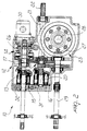
- Figure 2 is a partially sectional view of the transmission of Figure 1;
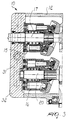
- Figure 3 is a sectional view of a detail of the transmission of Figure 1.
-
- With particular reference to Figures 1, 2 and 3, a mechanical-hydrostatic transmission, particularly for tools and vehicles suitable for gardening, such as lawn-mowers or the like, according to the invention, is generally designated by the
reference numeral 10. - In particular, the
transmission 10 is applied in this case to a compact tractor, generally designated by the reference numeral 11, which is outfitted as a lawn-mower. - The
transmission 10 comprises areduction unit 13, aclutch unit 14, anoil pump 15 and ahydraulic motor 16, which are integrated and contained within asingle casing 12 with acover 32. - The
pump 15 and theclutch unit 14 are arranged coaxially on afirst shaft 17 which is connected externally, by means of acoupling 18, to motor means generally designated by thereference numeral 19. - The
pump 15 is hydraulically connected to thehydraulic motor 16 and the motor is axially associated with asecond shaft 20 which is coaxially connected to athird shaft 21 which protrudes from thecasing 12 so as to form a power take-off 22. - The
casing 12 also contains kinematic connections, generally designated by thereference numeral 23, for the axles of the driving wheels, respectively designated by thereference numerals - In particular, in this embodiment the
oil pump 15 is of the variable-displacement type, and also thehydraulic motor 16 is of the variable-displacement type (and can also have a plurality of preset speed ranges). - Moreover, the
clutch unit 14 is constituted by adisk clutch 26. - The
kinematic connections 23 are constituted, in this case, by abevel gear pair 27 for anaxle 28 of the pair offront wheels 24 and by afourth shaft 29 for axial connection of therear wheels 25. - Moreover, the
transmission 10 comprises anauxiliary pump 30 which is associated externally with respect to thecasing 12, feeds the hydraulic steering system, the lifting of the tool, the auxiliary services and maintains the oil pressure on thepump 15 and thehydrostatic motor 16. -
Ducts 31, shown in dashed lines in the figures, are also formed in thecover 32 and provide circuits and connections between thepump 15 and themotor 16. - In practice, it has been observed that the present invention has achieved its intended aim and objects.
- In particular, it should be noted that the integration of the entire transmission within the same casing leads to a considerable simplification of the overall mechanical structure and of the oil circuit system, with a consequent reduction in production costs and a parallel increase in overall functionality and sturdiness.
- The structure of the transmission according to the invention in fact has a smaller number of components at risk of failure with respect to commercially available transmissions.
- It should also be noted that all the above, in terms of component reduction, has been achieved without reducing the functional capabilities of the transmission, which also allows, in use, considerable flexibility in terms of reduction and range of rotation rates.
- This last characteristic allows to apply the transmission according to the invention without additional reduction units.
- The present invention is susceptible of numerous modifications and variations, all of which are within the scope of the inventive concept.
- The technical details can be replaced with other technically equivalent elements.
- The materials and the dimensions may be any according to requirements.
- The disclosures in Italian Patent Application No. PD99A000165 from which this application claims priority are incorporated herein by reference.
- Where technical features mentioned in any claim are followed by reference signs, those reference signs have been included for the sole purpose of increasing the intelligibility of the claims and accordingly, such reference signs do not have any limiting effect on the interpretation of each element identified by way of example by such reference signs.
Claims (8)
- A mechanical-hydrostatic transmission, particularly for tools and vehicles suitable for gardening, such as lawn-mowers or the like, characterized in that it comprises a reduction unit, a clutch unit, an oil pump and a hydraulic motor which are integrated and contained within a single casing, said pump and said clutch unit being arranged coaxially on a first shaft which is connected externally, by means of a coupling, to motor means, said pump being hydraulically connected to said hydraulic motor and said hydraulic motor being axially associated with a second shaft from which a power take-off extends, said casing containing kinematic connections for transmitting motion to the driving wheels.
- The transmission according to claim 1, characterized in that said pump is of the variable-displacement type.
- The transmission according to claim 1, characterized in that said motor is of the variable-displacement type.
- The transmission according to claim 1, characterized in that said clutch unit is constituted by a disk clutch.
- The transmission according to claim 1, characterized in that said second shaft is coaxially connected to a third shaft which protrudes from said casing so as to form said power take-off.
- The transmission according to claim 1, characterized in that said kinematic connections are constituted by a bevel gear pair for the axle related to a pair of front wheels and by a fourth shaft for connection to an axle of rear wheels.
- The transmission according to claim 1, characterized in that it comprises an auxiliary pump which supplies a hydraulic steering system, the lifting of the tool, auxiliary services and maintains the pressure of the oil of said pump and of said hydraulic motor.
- The transmission according to claim 1, characterized in that in the cover of said casing there are one or more ducts for hydraulic connection between said pump and said hydraulic motor.
Applications Claiming Priority (2)
| Application Number | Priority Date | Filing Date | Title |
|---|---|---|---|
| IT1999PD000165A IT1307209B1 (en) | 1999-07-15 | 1999-07-15 | MECHANICAL / HYDROSTATIC TRANSMISSION PERFECTLY PERFORMED FOR EQUIPMENT AND VEHICLES SUITED FOR GARDENING WORKS TYPE MOWER CUTTER OR |
| ITPD990165 | 1999-07-15 |
Publications (2)
| Publication Number | Publication Date |
|---|---|
| EP1069345A2 true EP1069345A2 (en) | 2001-01-17 |
| EP1069345A3 EP1069345A3 (en) | 2002-02-27 |
Family
ID=11392688
Family Applications (1)
| Application Number | Title | Priority Date | Filing Date |
|---|---|---|---|
| EP00114127A Withdrawn EP1069345A3 (en) | 1999-07-15 | 2000-07-11 | Mechanical-hydrostatic transmission, particularly for agricultural vehicles such as lawn-mowers or the like |
Country Status (3)
| Country | Link |
|---|---|
| US (1) | US6443036B1 (en) |
| EP (1) | EP1069345A3 (en) |
| IT (1) | IT1307209B1 (en) |
Families Citing this family (2)
| Publication number | Priority date | Publication date | Assignee | Title |
|---|---|---|---|---|
| US6951091B2 (en) * | 2002-09-03 | 2005-10-04 | Norihiro Ishii | Riding lawn mower |
| US9290093B2 (en) * | 2013-11-26 | 2016-03-22 | Deere & Company | Supplemental power attachment for a vehicle |
Family Cites Families (7)
| Publication number | Priority date | Publication date | Assignee | Title |
|---|---|---|---|---|
| DE1171276B (en) | 1960-08-27 | 1964-05-27 | Kopat Ges Fuer Konstruktion | Vehicle transmissions, in particular for agricultural tractors in device carrier design |
| JPH075029B2 (en) * | 1987-12-29 | 1995-01-25 | 株式会社神崎高級工機製作所 | Self-propelled work vehicle transmission |
| JP2538356B2 (en) * | 1989-11-20 | 1996-09-25 | 株式会社神崎高級工機製作所 | Transmission system for self-propelled work vehicle |
| JP2517464Y2 (en) * | 1990-05-28 | 1996-11-20 | 株式会社神崎高級工機製作所 | Transmission device for work vehicles |
| JP3769030B2 (en) * | 1993-08-10 | 2006-04-19 | 株式会社 神崎高級工機製作所 | Hydraulic transmission |
| JPH07117500A (en) | 1993-10-22 | 1995-05-09 | Kanzaki Kokyukoki Mfg Co Ltd | Transmission for work vehicle |
| JP3824665B2 (en) | 1994-07-25 | 2006-09-20 | 株式会社 神崎高級工機製作所 | Work vehicle transmission |
-
1999
- 1999-07-15 IT IT1999PD000165A patent/IT1307209B1/en active
-
2000
- 2000-07-11 US US09/613,617 patent/US6443036B1/en not_active Expired - Fee Related
- 2000-07-11 EP EP00114127A patent/EP1069345A3/en not_active Withdrawn
Also Published As
| Publication number | Publication date |
|---|---|
| US6443036B1 (en) | 2002-09-03 |
| EP1069345A3 (en) | 2002-02-27 |
| IT1307209B1 (en) | 2001-10-29 |
| ITPD990165A1 (en) | 2001-01-15 |
Similar Documents
| Publication | Publication Date | Title |
|---|---|---|
| US6230830B1 (en) | Integrated splitter gearbox for four wheel drive tractors | |
| EP0153196B1 (en) | Transmission system for motor vehicles having pto-shafts | |
| CA1089773A (en) | Power transmission system for tractor | |
| DE102008033434B4 (en) | Vehicle powertrain with direct power source | |
| EP0893296A3 (en) | Driving system for a working vehicle | |
| JP2007099070A (en) | Power transmission device in working vehicle | |
| US20020003051A1 (en) | Power take-off assembly for working vehicles | |
| US7798280B2 (en) | Hydraulic steering system for a vehicle | |
| US11479116B2 (en) | Auxiliary power take-off assembly | |
| US6942041B1 (en) | Self-propelled agricultural vehicle constructed using a standard row-crop tractor as a base | |
| US6443036B1 (en) | Mechanical-hydrostatic transmission, particularly for tools and vehicles suitable for gardening, such as lawn-mowers or the like | |
| US20090126328A1 (en) | Working Vehicle With Front-Mount Mower | |
| US4862988A (en) | Four wheel drive working vehicle | |
| JP3321493B2 (en) | Transmission with hydraulic continuously variable transmission for work vehicles | |
| US6588531B1 (en) | Splitter gearbox vent tube | |
| US20020189885A1 (en) | Hydrostatic power system | |
| EP3916268B1 (en) | Low noise power take-off transmission | |
| JP2585484B2 (en) | Work vehicle | |
| JP2641656B2 (en) | Work vehicle transmission structure | |
| KR102788101B1 (en) | Power Take-off Apparatus of Agricultural Vehicle | |
| KR102262737B1 (en) | Power Take-off Apparatus of Agricultural Vehicle | |
| JPS6321808Y2 (en) | ||
| GB1562565A (en) | Power take-off means for vehicles | |
| GB1590461A (en) | Agricultural tractors | |
| JP2665697B2 (en) | Hydraulic transmission |
Legal Events
| Date | Code | Title | Description |
|---|---|---|---|
| PUAI | Public reference made under article 153(3) epc to a published international application that has entered the european phase |
Free format text: ORIGINAL CODE: 0009012 |
|
| AK | Designated contracting states |
Kind code of ref document: A2 Designated state(s): AT BE CH CY DE DK ES FI FR GB GR IE IT LI LU MC NL PT SE Kind code of ref document: A2 Designated state(s): DE FR |
|
| AX | Request for extension of the european patent |
Free format text: AL;LT;LV;MK;RO;SI |
|
| RIN1 | Information on inventor provided before grant (corrected) |
Inventor name: MARTIGNON, GIROLAMO |
|
| PUAL | Search report despatched |
Free format text: ORIGINAL CODE: 0009013 |
|
| AK | Designated contracting states |
Kind code of ref document: A3 Designated state(s): AT BE CH CY DE DK ES FI FR GB GR IE IT LI LU MC NL PT SE |
|
| AX | Request for extension of the european patent |
Free format text: AL;LT;LV;MK;RO;SI |
|
| RIC1 | Information provided on ipc code assigned before grant |
Free format text: 7F 16H 47/02 A, 7B 60K 17/28 B |
|
| 17P | Request for examination filed |
Effective date: 20020726 |
|
| AKX | Designation fees paid |
Free format text: DE FR |
|
| 17Q | First examination report despatched |
Effective date: 20030722 |
|
| GRAP | Despatch of communication of intention to grant a patent |
Free format text: ORIGINAL CODE: EPIDOSNIGR1 |
|
| STAA | Information on the status of an ep patent application or granted ep patent |
Free format text: STATUS: THE APPLICATION HAS BEEN WITHDRAWN |
|
| 18W | Application withdrawn |
Effective date: 20050623 |