EP1069343B1 - Belt for continuously variable transmission - Google Patents
Belt for continuously variable transmission Download PDFInfo
- Publication number
- EP1069343B1 EP1069343B1 EP99945692A EP99945692A EP1069343B1 EP 1069343 B1 EP1069343 B1 EP 1069343B1 EP 99945692 A EP99945692 A EP 99945692A EP 99945692 A EP99945692 A EP 99945692A EP 1069343 B1 EP1069343 B1 EP 1069343B1
- Authority
- EP
- European Patent Office
- Prior art keywords
- metal
- speed
- metal elements
- pulley
- metal element
- Prior art date
- Legal status (The legal status is an assumption and is not a legal conclusion. Google has not performed a legal analysis and makes no representation as to the accuracy of the status listed.)
- Expired - Lifetime
Links
- 230000005540 biological transmission Effects 0.000 title claims description 14
- 229910052751 metal Inorganic materials 0.000 claims description 176
- 239000002184 metal Substances 0.000 claims description 106
- 230000005484 gravity Effects 0.000 claims description 32
- 230000000712 assembly Effects 0.000 claims description 29
- 238000000429 assembly Methods 0.000 claims description 29
- 230000002093 peripheral effect Effects 0.000 description 16
- 230000003247 decreasing effect Effects 0.000 description 5
- 230000001105 regulatory effect Effects 0.000 description 3
- 238000000034 method Methods 0.000 description 2
- 230000001276 controlling effect Effects 0.000 description 1
- 230000008878 coupling Effects 0.000 description 1
- 238000010168 coupling process Methods 0.000 description 1
- 238000005859 coupling reaction Methods 0.000 description 1
- 230000000694 effects Effects 0.000 description 1
- 238000012986 modification Methods 0.000 description 1
- 230000004048 modification Effects 0.000 description 1
- 238000004080 punching Methods 0.000 description 1
Images


Classifications
-
- F—MECHANICAL ENGINEERING; LIGHTING; HEATING; WEAPONS; BLASTING
- F16—ENGINEERING ELEMENTS AND UNITS; GENERAL MEASURES FOR PRODUCING AND MAINTAINING EFFECTIVE FUNCTIONING OF MACHINES OR INSTALLATIONS; THERMAL INSULATION IN GENERAL
- F16G—BELTS, CABLES, OR ROPES, PREDOMINANTLY USED FOR DRIVING PURPOSES; CHAINS; FITTINGS PREDOMINANTLY USED THEREFOR
- F16G5/00—V-belts, i.e. belts of tapered cross-section
- F16G5/16—V-belts, i.e. belts of tapered cross-section consisting of several parts
Definitions
- the present invention relates to a belt for a continuously variable transmission, including a large number of metal elements supported on metal ring assemblies each of which is comprised of a plurality of endless metal rings laminated one on another.
- a pair of main surfaces 38 and 39 extending perpendicular to a direction of movement and parallel to each other are provided on front and rear sides of a metal element 32 in the direction of movement, and a slope 41 is formed radially inside the main surface 38 on the front side in the direction of movement so as to be continuous with the latter.
- a pair of adjacent ones of the metal elements 32 can be pitched relative to each other around a rocking edge 40 extending between the main surface 38 and the slope 41. Therefore, as shown in Fig.4, when the metal elements 32 are moved from a drive pulley 6 to a driven pulley 11, the main surfaces 38 and 39 of the adjacent ones of the metal elements 32 are placed in abutment against each other to transmit a driving force. When the metal elements 32 are in a state wound around the drive pulley 6 or the driven pulley 11, the interference of the metal elements 32 with each other can be avoided by the pitching around the rocking edge 40.
- the metal elements 32 of the belt for the continuously variable transmission perform a rectilinear translating movement in a chord portion of the belt between the drive pulley 6 and the driven pulley 11 and hence, the moving speeds of various portions of the metal element 32 are the same as one another.
- the metal elements 32 perform a rotating movement about rotational axes of the drive pulley 6 and the driven pulley 11 and hence, the moving speed of a radially outer portion of the metal element 32 is larger than that of a radially inner portion of the metal element 32.
- the speed of the rocking edge 40 of each of the metal elements 32 wound around the pulleys 6 and 11 is equal to the speed of the various portions of the metal elements 32 performing the rectilinear translating movement in the chord portion. Namely, the speed of the rocking edge 40 of the metal elements 32 at belt portions wound around the pulleys 6 and 11 and the speed of the rocking edge 40 of the metal elements 32 at belt portions which are not wound around the pulleys 6 and 11 (i.e., the chord portion), are the same as each other.
- the speed of the radially outer portion of the metal element 32 is larger than the speed of the rocking edge 40, and the speed of the radially inner portion of the metal element 32 than the rocking edge 40 is smaller than the speed of the rocking edge 40.
- the metal elements 32 lie in the chord portion between the drive pulley 6 and the driven pulley 11 to transmit the driving force, the main surfaces 38 and 39 of adjacent ones of the metal elements 32 are brought into close contact with each other and thus are prevented from being inclined.
- the metal elements 32 lie in the chord portion between the driven pulley 11 and the drive pulley 6 to transmit no driving force, a small gap is produced between the adjacent ones of the metal elements 32 and hence, in a portion A in Fig. 4, the metal elements 32 may be meshed with the drive pulley 6 while remaining inclined in the direction of movement (with the pitching remaining occurred) in some cases.
- the metal elements 32 are meshed with the drive pulley 6 while remaining inclined in the direction of movement, a movement for dissolving the pitching of the metal elements 32 and compacting the gap between the metal elements occurs in the chord portion near an outlet of the drive pulley 6 for resisting against an urging force acting between the elements and hence, the following problems arise: the wearing of the metal elements 32 and the pulley 6 is increased, and the power transmitting efficiency is reduced.
- JP-2-225840 A (or EP0377918 A1 ) is designed so that the center of gravity G of the metal element 32 is located in the vicinity of the rocking edge 40 or radially outside the rocking edge 40, thereby preventing a gap from being produced between the metal elements 32 in the chord portion between the driven pulley 11 and the drive pulley 6, so that the metal elements 32 in close contact with one another are smoothly meshed with the drive pulley 6.
- the speed of the center of gravity G of the metal elements 32 in the chord portion between the pulleys 6 and 11 is equal to the pitch circular speed, but the speed of the center of gravity G of the metal elements 32 wound around the pulleys 6 and 11 is larger than the pitch circular speed, if the center of gravity G lies radially outside the rocking edge 40.
- the kinetic energy of the metal elements 32 leaving the driven pulley 11 is larger than the kinetic energy of the metal elements 32 lying in the chord portion.
- the metal elements 32 lying in the chord portion are urged forwards (toward the drive pulley 6) by a difference between the kinetic energies and are smoothly meshed with the drive pulley 6 in a state placed in close contact with one another.
- the center of gravity G of the metal element 32 is allowed to lie radially inside the rocking edge 40 even at a distance of 0.5 mm from the latter.
- the center of gravity G lies radially inside the rocking edge 40, the kinetic energy of the metal element 32 leaving the driven pulley 11 becomes smaller than that of a metal element 32 lying in the chord portion and hence, the metal elements 32 lying in the chord portion cannot be meshed with the drive pulley 6 without being pitched in a state placed in close contact with one another. Therefore, it is required that the center of gravity G of the metal element 32 should lie radially outside the rocking edge 40.
- Vr represents a speed of the rocking edge 40 at an instant when the metal element 32 leaves the driven pulley 11, and Vg represents a speed of the center of gravity G of the metal element 32.
- a further belt for a continuously variable transmission, according to the preamble of claim 1, is known from JP 05 240 309 A .
- the present invention has been accomplished with the above circumstances in view, and it is an object of the present invention to ensure that the center of gravity of the metal elements is defined correctly in a proper range, whereby the metal elements lying in the chord portion are meshed with the drive pulley in the state free of the pitching.
- a belt for a continuously variable transmission as claimed in claim 1 comprising a large number of metal elements supported on metal ring assemblies each of which is comprised of a plurality of endless metal rings laminated one on another, the belt being wound around a drive pulley and a driven pulley to transmit a driving force between both of the pulleys, the metal elements including ring slots for supporting the metal ring assemblies, and are pitchably in abutment against one another with a rocking edge interposed there between.
- Vr ⁇ Vg ⁇ Vs
- Vr represents a speed of the rocking edge at an instant when the metal element leaves the driven pulley
- Vg represents a speed of the center of gravity of the metal element
- Vs represents a speed of a radially outer end of the ring slot.
- the speed Vg of the center of gravity of the metal elements is set larger than the speed Vr of the rocking edge at an instant when the metal elements leave the driven pulley. Therefore, the metal elements leaving the driven pulley have a kinetic energy larger than the metal elements lying in the chord portion, whereby the metal elements lying in the chord portion can forcibly be urged forwards and meshed with the drive pulley in a state placed in close contact with one another without being pitched.
- the speed Vg of the center of gravity of the metal elements is set smaller than the speed Vs of the radially outer end of the ring slot.
- Vr ⁇ Vk ⁇ Vg ⁇ Vs is established where Vk represents the speed of a radially inner end of the ring slot of the metal element.
- Fig.1 shows the skeleton structure of a metal belt-type continuously variable transmission T mounted on an automobile.
- An input shaft 3 is connected to a crankshaft 1 of an engine E through a damper 2 and also connected to a drive shaft 5 of the metal belt-type continuously variable transmission T through a starting clutch 4.
- a drive pulley 6 is mounted on the drive shaft 5 and includes a stationary pulley half 7 secured to the drive shaft 5, and a movable pulley half 8 which is movable toward and away from the stationary pulley half 7.
- the movable pulley half 8 is biased toward the stationary pulley half 7 by a hydraulic pressure applied to an oil chamber 9.
- a driven pulley 11 is mounted on a driven shaft 10 disposed in parallel to the drive shaft 5, and includes a stationary pulley half 12 secured to the driven shaft 10, and a movable pulley half 13 which is movable toward and away from the stationary pulley half 12.
- the movable pulley half 13 is biased toward the stationary pulley half 12 by a hydraulic pressure applied to an oil chamber 14.
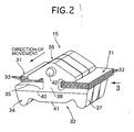
- a metal belt 15 comprising a large number of metal elements 32 supported on a pair of left and right metal ring assemblies 31, 31 is wound between the drive pulley 6 and the driven pulley 11 (see Fig.2).
- Each of the metal ring assemblies 31 comprises twelve metal rings 33 laminated one on another.
- a forward drive gear 16 and a backward drive gear 17 are rotatably carried on the driven shaft 10 and are capable of being selectively coupled to the driven shaft 10 by a selector 18. Secured to an output shaft 19 disposed in parallel to the driven shaft 10 are a forward driven gear 20 meshed with the forward drive gear 16, and a backward driven gear 22 meshed with the backward drive gear 17 through a backward idle gear 21.
- the rotation of the output shaft 19 is inputted to a differential 25 through a final drive gear 23 and a final driven gear 24 and then transmitted from the differential 25 through left and right axles 26, 26 to driven wheels W, W.
- a driving force from the engine E is transmitted through the crankshaft 1, the damper 2, the input shaft 3, the starting clutch 4, the drive shaft 5, the drive pulley 6, the metal belt 15 and the driven pulley 11 to the driven shaft 10.
- the driving force of the driven shaft 10 is transmitted through the forward drive gear 16 and the forward driven gear 20 to the output shaft 19 to move the vehicle forwards.
- the driving force of the driven shaft 10 is transmitted through the backward drive gear 17, the backward idle gear 21 and the backward driven gear 22 to the output shaft 19 to move the vehicle backwards.
- the shift ratio is continuously regulated by controlling the hydraulic pressures applied to the oil chamber 9 in the drive pulley 6 and the oil chamber 14 in the driven pulley 11 of the metal belt-type continuously variable transmission T by a hydraulic pressure control unit U 2 which is operated by a command from an electronic control unit U 1 . More specifically, if the hydraulic pressure applied to the oil chamber 14 in the driven pulley 11 is increased relative to the hydraulic pressure applied to the oil chamber 9 in the drive pulley 6, a groove width of the driven pulley 11 is decreased, leading to an increased effective radius. Attendant on this, a groove width of the drive pulley 6 is increased, leading to a decreased effective radius. Therefore, the shift ratio of the metal belt-type continuously variable transmission T is varied continuously toward "LOW".
- the metal element 32 formed from a metal plate by punching includes a substantially trapezoidal element body 34, and a substantially triangular ear portion 36 connected to an upper portion of the element body 34 through a pair of left and right ring slots 35, 35 into which the metal ring assemblies 31, 31 are fitted.
- a pair of pulley abutment surfaces 37, 37 are formed on left and right opposite edges of the element body 34, and are capable of abutting against V-surfaces of the drive pulley 6 and the driven pulley 11.
- a pair of front and rear main surfaces 38 and 39 perpendicular to a direction of movement and parallel to each other are formed on front and rear sides of the metal element 32 in the direction of movement, and a slope 41 is formed below the main surface 38 on the front side in the direction of movement with a laterally extending rocking edge 40 interposed therebetween. Further, a projection 42 and a recess 43 are formed respectively on the main surface 38 on the front side in the direction of movement and the main surface 39 on the rear side in the direction of movement, which correspond to the ear portion 36.
- a center of gravity G of the metal element 32 is located radially outside the rocking edge 40 and radially inside the radially outer ends 35 1 , 35 1 of the ring slots 35, 35.
- Vr speed of the rocking edge 40 at an instant when the metal element 32 leaves the driven pulley 11
- Vg speed of the center of gravity G of the metal element 32
- Vs speed of the radially outer ends 35 1 , 35 1 of the ring slots 35, 35
- the adjacent ones of the metal elements 32 lying in an advancing-side chord portion extending from the drive pulley 6 toward the driven pulley 11 (i.e., a chord port ion capable of transmitting the driving force) transmit the driving force in a state in which the main surfaces 38 of the front side of the metal element 32 and the main surface 39 of the rear side of the metal element 32 are in abutment against each other, and the projection 42 of the front side of the metal element 32 has been fitted in the recess 43 of the rear side of the metal element 32.
- the metal elements 32 wound around the drive pulley 6 and the driven pulley 11 are swung around the rocking edge 40 by releasing of the contact of the main surfaces 38 and 39 with each other, and are arranged radiately in a radial direction of the pulleys 6 and 11.
- the gap produced at the outlet side of the driven pulley 11 between the metal elements 32 on the returning-side chord portion is gradually decreased as approaching the drive pulley 6 and moreover, the inclined metal elements 32 are gradually risen and arranged in close contact with one another at the inlet side of the drive pulley 6, whereby they are meshed with the drive pulley 6 in an attitude free of pitching.
- the speed Vg of the center of gravity G of the metal element 32 is set smaller than the speed Vs of the radially outer ends 35 1 , 35 1 of the ring slots 35, 35, it can be prevented that the metal element 32 leaving the driven pulley 11 has an excessive kinetic energy to generate a large moment around the metal ring assemblies 31, 31, and the falling of the metal element 32 in the pitching direction can be previously avoided, whereby the metal elements 32 can be brought into close contact with one another and smoothly meshed with the drive pulley 6.
- Fig.5 shows a technique for regulating the position of the center of gravity G of the metal element 32.
- the lower edge of the element body 34 may be changed to a position 34 1
- the upper edge of the ear portion 36 may be changed to a position 36 1 .
- the lower edge of the element body 34 may be changed to a position 34 2
- the upper edge of the ear portion 36 may be changed to a position 36 2 .
- Vr ⁇ Vg ⁇ Vs when the speed of radially inner ends 35 2 , 35 2 of the ring slots 35, 35 (a saddle surface speed) is represented by Vk, if the relation Vr ⁇ Vk ⁇ Vg ⁇ Vs is established, further effects can be obtained, which will be described with reference to Figs.4 and 6 to 9.
- the speed Vr of the rocking edge 40 of the metal element 32 accords with the speed Vk of the radially inner ends 35 2 , 35 2 and the speed Vs of the radially outer ends 35 1 , 35 1 of the ring slots 35, 35. Therefore, if the inner peripheral surfaces of the metal ring assemblies 31, 31 interfere with the radially inner ends 35 2 , 35 2 of the ring slots 35, 35, the metal element 32 having a low speed is driven forwards by the metal ring assemblies 31, 31 having a high speed due to the friction force.
- the inner peripheral speed Va of the metal ring assemblies 31, 31 is substantially the same as the speed Vk DN of the radially inner ends 35 2 , 35 2 of the ring slots 35, 35 in the driven pulley 11.
- the inner peripheral speed Va of the metal ring assemblies 31, 31 is substantially the same as the speed Vk DR of the radially inner ends 35 2 , 35 2 of the ring slots 35, 35 in the drive pulley 6.
- the difference Vb - Vr between the outer peripheral speed Vb of the metal ring assemblies 31, 31 and the speed Vr of the rocking edge 40 can be obtained by defining the thickness of the metal ring assemblies 31, 31 as t and replacing d of the above theory with d + t.
- Vb > Vr is established in all the shift ratios.
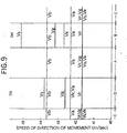
- Table 1 Speed of each portion in the advancing direction of the belt (m/sec) Name of portion Wound portion D of DR pulley Chord portions A, C Wound portion B of DN pulley Vs Outer end of slot 43.79 41.66 45.16 Vb Outer periphery of ring 43.67 43.67 43.67 Va Inner periphery of ring 42.30 42.30 42.30 Vk Inner end of slot 42.30 41.66 42.69 Vr Rocking edge 41.66 41.66 41.66 Vg Center of gravity 42.60 41.66 43.20
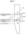
- Table 1 and Fig.9 show variations in the speeds Vs, Vb, Va, Vk, Vr and Vg of respective portions of the metal ring 15 at each of regions A, B, C and D when the transmission is operated at the maximum output with an input torque of 14.4 kgf-m, an input rotational speed of 6000 rpm and a shift ratio of 0.61 using the metal belt 15 having the metal elements 32 of the dimension shown in Fig. 7.
- the definition of each of the regions A, B, C and D of the metal ring 15 is shown in Fig.8.
- Vk ⁇ Vg ⁇ Vs should be established at least at an instant when the metal element 32 leaves the driven pulley 11, by positioning the center of gravity G of the metal element 32 between the radially outer ends 35 1 , 35 1 and the radially inner ends 35 2 , 35 2 of the ring slots 35, 35.
- Vr ⁇ Vg should be established between the speed Vr of the rocking edge 40 and the speed Vg of the center of gravity G at an instant when the metal element 32 leaves the driven pulley 11, and that the relation Vr ⁇ Vk should be established between the speed Vr of the rocking edge 40 and the speed Vk of the radially inner ends 35 2 , 35 2 of the ring slots 35, 35 in a general design of the metal belt 15. Considering them, it is required that the relation, Vr ⁇ Vk ⁇ Vg ⁇ Vs should finally be established.
- Vr ⁇ Vk ⁇ Vg ⁇ Vs is established, even when the action for compacting the gap between the metal elements 32 occurs in the chord portion extending from the driven pulley 11 toward the drive pulley 6, it is possible to maintain the pitching moment for falling the metal element 32 to the minimum and to smoothly bring the metal elements 32 in close contact with each other.
Landscapes
- Engineering & Computer Science (AREA)
- General Engineering & Computer Science (AREA)
- Mechanical Engineering (AREA)
- Transmissions By Endless Flexible Members (AREA)
Description
- The present invention relates to a belt for a continuously variable transmission, including a large number of metal elements supported on metal ring assemblies each of which is comprised of a plurality of endless metal rings laminated one on another.
- As shown in Figs.2 and 3, a pair of
main surfaces metal element 32 in the direction of movement, and aslope 41 is formed radially inside themain surface 38 on the front side in the direction of movement so as to be continuous with the latter. A pair of adjacent ones of themetal elements 32 can be pitched relative to each other around arocking edge 40 extending between themain surface 38 and theslope 41. Therefore, as shown in Fig.4, when themetal elements 32 are moved from adrive pulley 6 to a drivenpulley 11, themain surfaces metal elements 32 are placed in abutment against each other to transmit a driving force. When themetal elements 32 are in a state wound around thedrive pulley 6 or the drivenpulley 11, the interference of themetal elements 32 with each other can be avoided by the pitching around therocking edge 40. - The
metal elements 32 of the belt for the continuously variable transmission perform a rectilinear translating movement in a chord portion of the belt between thedrive pulley 6 and the drivenpulley 11 and hence, the moving speeds of various portions of themetal element 32 are the same as one another. However, in a state in which themetal elements 32 are wound around thedrive pulley 6 and the drivenpulley 11, themetal elements 32 perform a rotating movement about rotational axes of thedrive pulley 6 and the drivenpulley 11 and hence, the moving speed of a radially outer portion of themetal element 32 is larger than that of a radially inner portion of themetal element 32. - At this time, the
metal elements 32 wound around thepulleys rocking edge 40. Therefore, the speed of therocking edge 40 of each of themetal elements 32 wound around thepulleys 6 and 11 (the pitch circular speed) is equal to the speed of the various portions of themetal elements 32 performing the rectilinear translating movement in the chord portion. Namely, the speed of therocking edge 40 of themetal elements 32 at belt portions wound around thepulleys rocking edge 40 of themetal elements 32 at belt portions which are not wound around thepulleys 6 and 11 (i.e., the chord portion), are the same as each other. Therefore, in the state in which themetal elements 32 are wound around thepulleys metal element 32 is larger than the speed of therocking edge 40, and the speed of the radially inner portion of themetal element 32 than therocking edge 40 is smaller than the speed of therocking edge 40. - Now, when the
metal elements 32 lie in the chord portion between thedrive pulley 6 and the drivenpulley 11 to transmit the driving force, themain surfaces metal elements 32 are brought into close contact with each other and thus are prevented from being inclined. However, when themetal elements 32 lie in the chord portion between the drivenpulley 11 and thedrive pulley 6 to transmit no driving force, a small gap is produced between the adjacent ones of themetal elements 32 and hence, in a portion A in Fig. 4, themetal elements 32 may be meshed with thedrive pulley 6 while remaining inclined in the direction of movement (with the pitching remaining occurred) in some cases. If themetal elements 32 are meshed with thedrive pulley 6 while remaining inclined in the direction of movement, a movement for dissolving the pitching of themetal elements 32 and compacting the gap between the metal elements occurs in the chord portion near an outlet of thedrive pulley 6 for resisting against an urging force acting between the elements and hence, the following problems arise: the wearing of themetal elements 32 and thepulley 6 is increased, and the power transmitting efficiency is reduced. - Therefore, a belt for a continuously variable transmission described in
-
JP-2-225840 A EP0377918 A1 ) is designed so that the center of gravity G of themetal element 32 is located in the vicinity of therocking edge 40 or radially outside therocking edge 40, thereby preventing a gap from being produced between themetal elements 32 in the chord portion between the drivenpulley 11 and thedrive pulley 6, so that themetal elements 32 in close contact with one another are smoothly meshed with thedrive pulley 6. - More specifically, the speed of the center of gravity G of the
metal elements 32 in the chord portion between thepulleys metal elements 32 wound around thepulleys rocking edge 40. In other words, the kinetic energy of themetal elements 32 leaving the drivenpulley 11 is larger than the kinetic energy of themetal elements 32 lying in the chord portion. Themetal elements 32 lying in the chord portion are urged forwards (toward the drive pulley 6) by a difference between the kinetic energies and are smoothly meshed with thedrive pulley 6 in a state placed in close contact with one another. - In the prior art described above, the center of gravity G of the
metal element 32 is allowed to lie radially inside therocking edge 40 even at a distance of 0.5 mm from the latter. However, if the center of gravity G lies radially inside therocking edge 40, the kinetic energy of themetal element 32 leaving the drivenpulley 11 becomes smaller than that of ametal element 32 lying in the chord portion and hence, themetal elements 32 lying in the chord portion cannot be meshed with thedrive pulley 6 without being pitched in a state placed in close contact with one another. Therefore, it is required that the center of gravity G of themetal element 32 should lie radially outside therocking edge 40. In other words, it is required that a relation Vr < Vg should be established when Vr represents a speed of therocking edge 40 at an instant when themetal element 32 leaves the drivenpulley 11, and Vg represents a speed of the center of gravity G of themetal element 32. - Additionally, if the center of gravity G of the
metal element 32 moves radially outside too far away from therocking edge 40, the kinetic energy of themetal elements 32 which have left the drivenpulley 11 becomes excessive and themetal elements 32 rotate so as to fall forwards, as shown in Fig.10. As a result, the energy is expended by the interference between ametal ring assembly 31 and a lower portion of anear portion 36, or by the interference of coupling, thereby resulting in loss of a force for delivering themetal elements 32 forwards. Therefore, there is a possibility that themetal elements 32 could not be meshed with thedrive pulley 6 in the state free of the pitching. - A further belt for a continuously variable transmission, according to the preamble of claim 1, is known from
JP 05 240 309 A - The present invention has been accomplished with the above circumstances in view, and it is an object of the present invention to ensure that the center of gravity of the metal elements is defined correctly in a proper range, whereby the metal elements lying in the chord portion are meshed with the drive pulley in the state free of the pitching.
- To achieve the above object, according to the present invention, there is provided a belt for a continuously variable transmission as claimed in claim 1, comprising a large number of metal elements supported on metal ring assemblies each of which is comprised of a plurality of endless metal rings laminated one on another, the belt being wound around a drive pulley and a driven pulley to transmit a driving force between both of the pulleys, the metal elements including ring slots for supporting the metal ring assemblies, and are pitchably in abutment against one another with a rocking edge interposed there between. The following relation is established:

wherein Vr represents a speed of the rocking edge at an instant when the metal element leaves the driven pulley; Vg represents a speed of the center of gravity of the metal element; and Vs represents a speed of a radially outer end of the ring slot. - With the above arrangement, the speed Vg of the center of gravity of the metal elements is set larger than the speed Vr of the rocking edge at an instant when the metal elements leave the driven pulley. Therefore, the metal elements leaving the driven pulley have a kinetic energy larger than the metal elements lying in the chord portion, whereby the metal elements lying in the chord portion can forcibly be urged forwards and meshed with the drive pulley in a state placed in close contact with one another without being pitched. In addition, the speed Vg of the center of gravity of the metal elements is set smaller than the speed Vs of the radially outer end of the ring slot. Therefore, it can be avoided previously that the metal elements leaving the driven pulley are fallen down in a direction of movement with an excessive kinetic energy, whereby the metal elements lying in the chord portion can be smoothly brought into close contact with one another and meshed with the drive pulley without being pitched.
- In addition, a relation, Vr < Vk < Vg < Vs is established where Vk represents the speed of a radially inner end of the ring slot of the metal element.
- With the above arrangement, when an action for compacting a gap between the metal elements occurs at the chord portion extending from the driven pulley toward the drive pulley, a pitching moment acting on the metal elements can be reduced to enable the metal elements to be smoothly brought into close contact with one another.
-
- Figs.1 to 9 show an embodiment of the present invention. Fig. 1 is a skeleton illustration of a power transmitting system in a vehicle having a continuously variable transmission mounted thereon; Fig.2 is a perspective view of a metal belt section; Fig.3 is a view taken in the direction of an
arrow 3 in Fig.2; Fig.4 is a view of a metal belt wound around a drive pulley and a driven pulley; Fig.5 is a view for explaining a technique for regulating the center of gravity of a metal element; Fig.6 is a view for explaining a relation, Vr < Vk < Vg < Vs, corresponding to Fig.3; Fig.7 is a view showing a dimension of each portion of the metal element; Fig.8 is a view showing each region of the metal belt; Fig.9 is a graph showing a variation of speed in each region of the metal belt; and Fig.10 is a view for explaining the problems of the prior art. - The mode for carrying out the present invention will now be described by way of an embodiment of the present invention shown in the accompanying drawings.
- Fig.1 shows the skeleton structure of a metal belt-type continuously variable transmission T mounted on an automobile. An
input shaft 3 is connected to a crankshaft 1 of an engine E through adamper 2 and also connected to adrive shaft 5 of the metal belt-type continuously variable transmission T through a starting clutch 4. Adrive pulley 6 is mounted on thedrive shaft 5 and includes a stationary pulley half 7 secured to thedrive shaft 5, and amovable pulley half 8 which is movable toward and away from the stationary pulley half 7. Themovable pulley half 8 is biased toward the stationary pulley half 7 by a hydraulic pressure applied to anoil chamber 9. - A driven
pulley 11 is mounted on a drivenshaft 10 disposed in parallel to thedrive shaft 5, and includes astationary pulley half 12 secured to the drivenshaft 10, and amovable pulley half 13 which is movable toward and away from thestationary pulley half 12. Themovable pulley half 13 is biased toward thestationary pulley half 12 by a hydraulic pressure applied to anoil chamber 14. Ametal belt 15 comprising a large number ofmetal elements 32 supported on a pair of left and rightmetal ring assemblies drive pulley 6 and the driven pulley 11 (see Fig.2). Each of themetal ring assemblies 31 comprises twelvemetal rings 33 laminated one on another. - A
forward drive gear 16 and a backwarddrive gear 17 are rotatably carried on the drivenshaft 10 and are capable of being selectively coupled to the drivenshaft 10 by aselector 18. Secured to anoutput shaft 19 disposed in parallel to the drivenshaft 10 are a forward drivengear 20 meshed with theforward drive gear 16, and a backward drivengear 22 meshed with the backwarddrive gear 17 through a backwardidle gear 21. - The rotation of the
output shaft 19 is inputted to adifferential 25 through afinal drive gear 23 and a final drivengear 24 and then transmitted from thedifferential 25 through left andright axles - A driving force from the engine E is transmitted through the crankshaft 1, the
damper 2, theinput shaft 3, the starting clutch 4, thedrive shaft 5, thedrive pulley 6, themetal belt 15 and the drivenpulley 11 to the drivenshaft 10. When a forward travel range is selected, the driving force of the drivenshaft 10 is transmitted through theforward drive gear 16 and the forward drivengear 20 to theoutput shaft 19 to move the vehicle forwards. When a backward travel range is selected, the driving force of the drivenshaft 10 is transmitted through the backwarddrive gear 17, the backwardidle gear 21 and the backward drivengear 22 to theoutput shaft 19 to move the vehicle backwards. - During this time, the shift ratio is continuously regulated by controlling the hydraulic pressures applied to the
oil chamber 9 in thedrive pulley 6 and theoil chamber 14 in the drivenpulley 11 of the metal belt-type continuously variable transmission T by a hydraulic pressure control unit U2 which is operated by a command from an electronic control unit U1. More specifically, if the hydraulic pressure applied to theoil chamber 14 in the drivenpulley 11 is increased relative to the hydraulic pressure applied to theoil chamber 9 in thedrive pulley 6, a groove width of the drivenpulley 11 is decreased, leading to an increased effective radius. Attendant on this, a groove width of thedrive pulley 6 is increased, leading to a decreased effective radius. Therefore, the shift ratio of the metal belt-type continuously variable transmission T is varied continuously toward "LOW". Reversely, if the hydraulic pressure applied to theoil chamber 9 in thedrive pulley 6 is increased relative to the hydraulic pressure applied to theoil chamber 14 in the drivenpulley 11, the groove width of thedrive pulley 6 is decreased, leading to an increased effective radius. Attendant on this, the groove width of the drivenpulley 11 is increased, leading to a decreased effective radius. Therefore, the shift ratio of the metal belt-type continuously variable transmission T is varied continuously toward "OD". - As shown in Figs.2 and 3, the
metal element 32 formed from a metal plate by punching includes a substantiallytrapezoidal element body 34, and a substantiallytriangular ear portion 36 connected to an upper portion of theelement body 34 through a pair of left andright ring slots metal ring assemblies element body 34, and are capable of abutting against V-surfaces of thedrive pulley 6 and the drivenpulley 11. A pair of front and rearmain surfaces metal element 32 in the direction of movement, and aslope 41 is formed below themain surface 38 on the front side in the direction of movement with a laterally extending rockingedge 40 interposed therebetween. Further, aprojection 42 and arecess 43 are formed respectively on themain surface 38 on the front side in the direction of movement and themain surface 39 on the rear side in the direction of movement, which correspond to theear portion 36. - As can be seen from Fig.3, a center of gravity G of the
metal element 32 is located radially outside the rockingedge 40 and radially inside the radially outer ends 351, 351 of thering slots edge 40 at an instant when themetal element 32 leaves the drivenpulley 11 is represented by Vr; the speed of the center of gravity G of themetal element 32 is by Vg; and the speed of the radially outer ends 351, 351 of thering slots - As shown in Fig.4, the adjacent ones of the
metal elements 32 lying in an advancing-side chord portion extending from thedrive pulley 6 toward the driven pulley 11 (i.e., a chord port ion capable of transmitting the driving force) transmit the driving force in a state in which themain surfaces 38 of the front side of themetal element 32 and themain surface 39 of the rear side of themetal element 32 are in abutment against each other, and theprojection 42 of the front side of themetal element 32 has been fitted in therecess 43 of the rear side of themetal element 32. Themetal elements 32 wound around thedrive pulley 6 and the drivenpulley 11 are swung around the rockingedge 40 by releasing of the contact of themain surfaces pulleys - On the other hand, a small gap is produced at an outlet side of the driven
pulley 11 between themetal elements 32 lying in a returning-side chord portion extending from the drivenpulley 11 toward the drive pulley 6 (i.e., a chord portion incapable of transmitting the driving force). For this reason, themetal elements 32, which cannot maintain the attitude with themain surfaces metal element 32 is set larger than the speed Vr of the rockingedge 40 at an instant when themetal element 32 is moved away from the drivenpulley 11, themetal element 32 leaving the drivenpulley 11 is released to the returning-side chord portion with a kinetic energy larger than that of themetal element 32 lying in the returning-side chord portion. Therefore, theelement 32 on the chord portion can be forcibly urged toward thedrive pulley 6 with such vigor. As a result, the gap produced at the outlet side of the drivenpulley 11 between themetal elements 32 on the returning-side chord portion is gradually decreased as approaching thedrive pulley 6 and moreover, theinclined metal elements 32 are gradually risen and arranged in close contact with one another at the inlet side of thedrive pulley 6, whereby they are meshed with thedrive pulley 6 in an attitude free of pitching. Thus, it is possible to eliminate a problem that the wearing of themetal elements 32 and thedrive pulley 6 is increased, and a problem that the power transmitting efficiency is reduced. - Moreover, since the speed Vg of the center of gravity G of the
metal element 32 is set smaller than the speed Vs of the radially outer ends 351, 351 of thering slots metal element 32 leaving the drivenpulley 11 has an excessive kinetic energy to generate a large moment around themetal ring assemblies metal element 32 in the pitching direction can be previously avoided, whereby themetal elements 32 can be brought into close contact with one another and smoothly meshed with thedrive pulley 6. - Fig.5 shows a technique for regulating the position of the center of gravity G of the
metal element 32. To move the center of gravity G of themetal element 32 radially outwards . (upwards in Fig.5), the lower edge of theelement body 34 may be changed to aposition 341, and/or the upper edge of theear portion 36 may be changed to aposition 361. To move the center of gravity G of themetal element 32 radially inwards (downwards in Fig.5), the lower edge of theelement body 34 may be changed to aposition 342, and/or the upper edge of theear portion 36 may be changed to aposition 362. - It should be noted here that in addition to the above-described relation, Vr < Vg < Vs, when the speed of radially inner ends 352, 352 of the
ring slots 35, 35 (a saddle surface speed) is represented by Vk, if the relation Vr < Vk < Vg < Vs is established, further effects can be obtained, which will be described with reference to Figs.4 and 6 to 9. - As shown in Fig.6, small vertical drags N, N act between the radially outer ends 351, 351 and the radially inner ends 352, 352 of the
ring slots metal ring assemblies metal ring assemblies edge 40 in themetal element 32, and the relation is Va > Vr and Vb > Vr as will be described below. - In the chord portion with which the
metal elements 32 move in parallel, the speed Vr of the rockingedge 40 of themetal element 32 accords with the speed Vk of the radially inner ends 352, 352 and the speed Vs of the radially outer ends 351, 351 of thering slots metal ring assemblies ring slots metal element 32 having a low speed is driven forwards by themetal ring assemblies metal ring assemblies ring slots metal element 32 having a low speed is driven forwards by themetal ring assemblies metal elements 32 occurs in the chord portion. - Here, the reason why the relations, Va > Vr and Vb > Vr are established will be described below.
- In Fig.4, when the speed of the rocking
edge 40 of themetal element 32 in the chord portion between thedrive pulley 6 and the driven pulley 11 (the speed of a pitch line) is represented by Vr, an angular speed of thedrive pulley 6 is by ωDR, an angular speed of the drivenpulley 11 by ωDN, a pitch radius of thedrive pulley 6 by RDR, and a pitch radius of the drivenpulley 11 by RDN, the following equations are established:

- Here, when d represents the difference between the radius of radially inner ends 352, 352 of the
ring slots 35, 35 (a radius of the saddle surface) and the pitch radii RDR, RDN, the speeds VkDR and VkDN of the radially inner ends 352, 352 of thering slots drive pulley 6 and the driven pulley 11 (a saddle surface speed) are given by the following equations, respectively:

- When the shift ratio is in the "LOW" side from 1.0, at the side of the driven
pulley 11, the radially inner ends 352, 352 of thering slots metal ring 33 rotate substantially without relative slipping. Therefore, the inner peripheral speed Va of themetal ring assemblies ring slots pulley 11. - Therefore, if the difference between the inner peripheral speed Va of the
metal ring assemblies edge 40 is calculated, the following equation can be obtained:
and the inner peripheral speed Va of themetal ring assemblies edge 40. - Further, when the shift ratio is in the "OD" side from 1.0, at the side of the
drive pulley 6, the radially inner ends 352, 352 of thering slots metal ring 33 rotate substantially without relative slipping. Therefore, the inner peripheral speed Va of themetal ring assemblies ring slots drive pulley 6. - Therefore, if the difference between the inner peripheral speed Va of the
metal ring assemblies edge 40 is calculated, the following equation can be obtained:
and the inner peripheral speed Va of themetal ring assemblies edge 40. - From the foregoing, the relation, Va > Vr is established in all the shift ratios.
- On the other hand, the difference Vb - Vr between the outer peripheral speed Vb of the
metal ring assemblies edge 40 can be obtained by defining the thickness of themetal ring assemblies pulley 11, the outer peripheral speed Vb of themetal ring assemblies ring slots 
and the outer peripheral speed Vb of themetal ring assemblies edge 40. - When the shift ratio is in the "OD" side from 1.0, at the side of the
drive pulley 6, the outer peripheral speed Vb of themetal ring assemblies ring slots 
and the outer peripheral speed Vb of themetal ring assemblies edge 40. - From the foregoing, the relation, Vb > Vr is established in all the shift ratios.
Table 1 Speed of each portion in the advancing direction of the belt (m/sec) Name of portion Wound portion D of DR pulley Chord portions A, C Wound portion B of DN pulley Vs Outer end of slot 43.79 41.66 45.16 Vb Outer periphery of ring 43.67 43.67 43.67 Va Inner periphery of ring 42.30 42.30 42.30 Vk Inner end of slot 42.30 41.66 42.69 Vr Rocking edge 41.66 41.66 41.66 Vg Center of gravity 42.60 41.66 43.20 - Table 1 and Fig.9 show variations in the speeds Vs, Vb, Va, Vk, Vr and Vg of respective portions of the
metal ring 15 at each of regions A, B, C and D when the transmission is operated at the maximum output with an input torque of 14.4 kgf-m, an input rotational speed of 6000 rpm and a shift ratio of 0.61 using themetal belt 15 having themetal elements 32 of the dimension shown in Fig. 7. The definition of each of the regions A, B, C and D of themetal ring 15 is shown in Fig.8. - As is apparent from Table 1 and Fig. 9, it can be seen that in the chord portions A and C at which the
metal elements 32 move in parallel, the speed Vs of the radially outer ends 351, 351 of thering slots ring slots edge 40 and the speed Vg of the center of gravity G are the same, and that the outer and inner peripheral speeds Vb and Va of themetal ring assemblies metal element 32. Additionally, it can be seen that the speed Vg of the center of gravity G in the regions B and D where themetal elements 32 are wound around the drivenpulley 11 and thedrive pulley 6 exceeds the speed Vg of the center of gravity G in the chord portions A and C. - Now, returning to the explanation of Fig.6, in the chord portion on which the urging force acting between the elements does not act, the frictional forces µN, µN (µ is a coefficient of friction) acting from the
metal ring assemblies metal element 32 by the vertical drags N, N act on the radially outer ends 351, 351 or radially inner ends 352, 352 of thering slots ring slots metal element 32 is positioned between the radially outer ends 351, 351 and the radially inner ends 352, 352 of thering slots ring slots ring slots - If the center of gravity G deviates from the range between the radially outer ends 351, 351 and the radially inner ends 352, 352 of the
ring slots metal element 32 might be unstable in the chord portion on which the urging force acting between the elements does not act. Therefore, in order to stabilize the behavior of themetal element 32 in the chord portion, it is required that the relation, Vk < Vg < Vs should be established at least at an instant when themetal element 32 leaves the drivenpulley 11, by positioning the center of gravity G of themetal element 32 between the radially outer ends 351, 351 and the radially inner ends 352, 352 of thering slots - Further, as is described in "BACKGROUND ART ", it is required that the relation, Vr < Vg should be established between the speed Vr of the rocking
edge 40 and the speed Vg of the center of gravity G at an instant when themetal element 32 leaves the drivenpulley 11, and that the relation Vr < Vk should be established between the speed Vr of the rockingedge 40 and the speed Vk of the radially inner ends 352, 352 of thering slots metal belt 15. Considering them, it is required that the relation, Vr < Vk < Vg < Vs should finally be established. If the relation, Vr < Vk < Vg < Vs is established, even when the action for compacting the gap between themetal elements 32 occurs in the chord portion extending from the drivenpulley 11 toward thedrive pulley 6, it is possible to maintain the pitching moment for falling themetal element 32 to the minimum and to smoothly bring themetal elements 32 in close contact with each other. - Although the embodiment of the present invention has been described in detail, it will be understood that the present invention is not limited to the above-described embodiment, and various modifications in design may be made without departing from the subject matter of the invention.
Claims (1)
- A belt for a continuously variable transmission, comprising a large number of metal elements (32) supported on metal ring assemblies (31) each of which is comprised of a plurality of endless metal rings (33) laminated one on another, said belt being wound around a drive pulley (6) and a driven pulley (11) to transmit a driving force between both of said pulleys (6 and 11),
said metal elements (32) including ring slots (35) for supporting said metal ring assemblies (31), and being pitchably in abutment against one another with a rocking edge (40) interposed therebetween,
characterized in that
the following relation is established:
wherein, at an instant when said metal element (32) leaves said driven pulleys (11), Vr represents a speed of the said rocking edge (40); Vg represents a speed of the center of gravity (G) of said metal elements (32); Vs represents a speed of a radially outer end (351) of said ring slot (35), and Vk represents the speed of a radially inner end (352) of said ring slot (35) of said metal element (32).
Applications Claiming Priority (5)
| Application Number | Priority Date | Filing Date | Title |
|---|---|---|---|
| JP9866498 | 1998-04-10 | ||
| JP9866498 | 1998-04-10 | ||
| JP3480199 | 1999-02-12 | ||
| JP11034801A JPH11351335A (en) | 1998-04-10 | 1999-02-12 | Belt for continuously variable transmission |
| PCT/JP1999/001110 WO1999053219A1 (en) | 1998-04-10 | 1999-03-08 | Belt for continuously variable transmission |
Publications (3)
| Publication Number | Publication Date |
|---|---|
| EP1069343A1 EP1069343A1 (en) | 2001-01-17 |
| EP1069343A4 EP1069343A4 (en) | 2006-05-31 |
| EP1069343B1 true EP1069343B1 (en) | 2007-10-31 |
Family
ID=26373645
Family Applications (1)
| Application Number | Title | Priority Date | Filing Date |
|---|---|---|---|
| EP99945692A Expired - Lifetime EP1069343B1 (en) | 1998-04-10 | 1999-03-08 | Belt for continuously variable transmission |
Country Status (5)
| Country | Link |
|---|---|
| US (1) | US6332854B1 (en) |
| EP (1) | EP1069343B1 (en) |
| JP (1) | JPH11351335A (en) |
| DE (1) | DE69937448T2 (en) |
| WO (1) | WO1999053219A1 (en) |
Families Citing this family (16)
| Publication number | Priority date | Publication date | Assignee | Title |
|---|---|---|---|---|
| DE60005746T2 (en) * | 1999-06-18 | 2004-04-29 | Honda Giken Kogyo K.K. | Belt for continuously variable transmission |
| JP3715166B2 (en) * | 2000-01-19 | 2005-11-09 | 本田技研工業株式会社 | Belt for continuously variable transmission |
| EP1221561A1 (en) * | 2000-12-28 | 2002-07-10 | Van Doorne's Transmissie B.V. | Belt |
| US20030215565A1 (en) * | 2001-10-10 | 2003-11-20 | Industrial Technology Research Institute | Method and apparatus for the formation of laminated circuit having passive components therein |
| NL1022022C2 (en) | 2002-11-28 | 2004-06-02 | Doornes Transmissie Bv | Metal drive belt. |
| JP4424376B2 (en) * | 2007-06-06 | 2010-03-03 | トヨタ自動車株式会社 | Transmission belt |
| DE112009005483T5 (en) | 2009-12-26 | 2012-10-04 | Toyota Jidosha Kabushiki Kaisha | Elements of a belt for a continuously variable vehicle transmission and method of manufacturing the elements |
| NL1038481C2 (en) * | 2010-12-28 | 2012-07-02 | Bosch Gmbh Robert | Transverse element with a protruding conical stud for a drive belt. |
| CN102906452B (en) * | 2011-05-27 | 2015-05-20 | 丰田自动车株式会社 | Drive belt and assembly method for drive belt |
| CN104334917B (en) * | 2012-07-06 | 2016-03-09 | 本田技研工业株式会社 | Metal tape element |
| NL1039980C2 (en) * | 2012-12-28 | 2014-07-03 | Bosch Gmbh Robert | Transverse segment for a drive belt with a carrier ring and multiple transverse segments. |
| JP6506062B2 (en) * | 2015-03-24 | 2019-04-24 | 本田技研工業株式会社 | Method of manufacturing metal element for continuously variable transmission |
| JP6444355B2 (en) * | 2016-11-04 | 2018-12-26 | 本田技研工業株式会社 | Metal element for continuously variable transmission and method for manufacturing metal element for continuously variable transmission |
| WO2018159858A1 (en) * | 2017-03-03 | 2018-09-07 | アイシン・エィ・ダブリュ株式会社 | Element design method and transmission belt |
| CN107816509B (en) * | 2017-11-02 | 2021-01-19 | 陈学琴 | Transmission belt of movable-plate continuously variable transmission |
| NL1043501B1 (en) * | 2019-12-10 | 2021-08-31 | Bosch Gmbh Robert | A transverse segment for a drive belt and a drive belt for a continuously variable transmission including the transverse segment and a ring stack |
Family Cites Families (12)
| Publication number | Priority date | Publication date | Assignee | Title |
|---|---|---|---|---|
| US4280455A (en) * | 1978-01-30 | 1981-07-28 | Fuji Jukogyo Kabushiki Kaisha | Internal combustion engine |
| JPS59197642A (en) * | 1983-04-25 | 1984-11-09 | Toyota Motor Corp | Power transmission belt |
| NL8400213A (en) * | 1984-01-24 | 1985-08-16 | Doornes Transmissie Bv | DRIVE BELT FOR APPLICATION TO V-SHAPED PULLEYS. |
| EP0257646B1 (en) * | 1986-08-28 | 1992-01-29 | Bando Chemical Industries, Ltd. | V belt with blocks |
| NL8900072A (en) * | 1989-01-12 | 1990-08-01 | Doornes Transmissie Bv | CROSS-ELEMENT FOR A BELT. |
| JPH0355943U (en) * | 1989-10-05 | 1991-05-29 | ||
| JP2529017B2 (en) * | 1990-07-25 | 1996-08-28 | 日産自動車株式会社 | Transmission belt |
| JPH05240309A (en) | 1992-02-28 | 1993-09-17 | Mitsuboshi Belting Ltd | Heavy load transmission belt |
| JP3206307B2 (en) * | 1994-07-07 | 2001-09-10 | 日産自動車株式会社 | Assembling type transmission V belt |
| JPH0914357A (en) * | 1995-06-27 | 1997-01-14 | Honda Motor Co Ltd | Block for transmission belt |
| JP3136999B2 (en) * | 1996-07-30 | 2001-02-19 | 日産自動車株式会社 | V-belt for continuously variable transmission |
| JP3689255B2 (en) * | 1998-06-05 | 2005-08-31 | 本田技研工業株式会社 | Metal V belt |
-
1999
- 1999-02-12 JP JP11034801A patent/JPH11351335A/en active Pending
- 1999-03-08 US US09/581,219 patent/US6332854B1/en not_active Expired - Fee Related
- 1999-03-08 DE DE69937448T patent/DE69937448T2/en not_active Expired - Lifetime
- 1999-03-08 EP EP99945692A patent/EP1069343B1/en not_active Expired - Lifetime
- 1999-03-08 WO PCT/JP1999/001110 patent/WO1999053219A1/en not_active Ceased
Also Published As
| Publication number | Publication date |
|---|---|
| DE69937448D1 (en) | 2007-12-13 |
| EP1069343A1 (en) | 2001-01-17 |
| US6332854B1 (en) | 2001-12-25 |
| JPH11351335A (en) | 1999-12-24 |
| DE69937448T2 (en) | 2008-08-21 |
| WO1999053219A1 (en) | 1999-10-21 |
| EP1069343A4 (en) | 2006-05-31 |
Similar Documents
| Publication | Publication Date | Title |
|---|---|---|
| EP1069343B1 (en) | Belt for continuously variable transmission | |
| EP1069342B1 (en) | Belt for continuously variable transmission | |
| EP1067311B1 (en) | Belt for continuously variable transmission | |
| EP1172582B1 (en) | Belt for non-stage transmissions | |
| JP3319995B2 (en) | Belt for continuously variable transmission | |
| US6612954B2 (en) | Belt for continuously variable transmission | |
| US6270437B1 (en) | Belt for continuously variable transmission | |
| EP1069341A1 (en) | Belt for continuously variable transmission | |
| EP1231407B1 (en) | Belt for continuously variable transmission | |
| EP1179691B1 (en) | Belt for continuously variable transmission | |
| EP1179689B1 (en) | Belt for continuously variable transmission | |
| US6336884B1 (en) | Belt for continuously variable transmission | |
| US6626783B1 (en) | Belt for continuously variable transmission | |
| EP1138976B1 (en) | Process for combining metal elements in belt for continuously variable transmission and belt | |
| JP7364719B2 (en) | Continuously variable transmission | |
| EP4563849A1 (en) | Driven clutch with dual helix assembly for continuously variable transmission |
Legal Events
| Date | Code | Title | Description |
|---|---|---|---|
| PUAI | Public reference made under article 153(3) epc to a published international application that has entered the european phase |
Free format text: ORIGINAL CODE: 0009012 |
|
| 17P | Request for examination filed |
Effective date: 20000619 |
|
| AK | Designated contracting states |
Kind code of ref document: A1 Designated state(s): DE FR GB NL |
|
| A4 | Supplementary search report drawn up and despatched |
Effective date: 20060418 |
|
| 17Q | First examination report despatched |
Effective date: 20060905 |
|
| GRAP | Despatch of communication of intention to grant a patent |
Free format text: ORIGINAL CODE: EPIDOSNIGR1 |
|
| GRAS | Grant fee paid |
Free format text: ORIGINAL CODE: EPIDOSNIGR3 |
|
| GRAA | (expected) grant |
Free format text: ORIGINAL CODE: 0009210 |
|
| AK | Designated contracting states |
Kind code of ref document: B1 Designated state(s): DE FR GB NL |
|
| REG | Reference to a national code |
Ref country code: GB Ref legal event code: FG4D |
|
| REF | Corresponds to: |
Ref document number: 69937448 Country of ref document: DE Date of ref document: 20071213 Kind code of ref document: P |
|
| ET | Fr: translation filed | ||
| PLBE | No opposition filed within time limit |
Free format text: ORIGINAL CODE: 0009261 |
|
| STAA | Information on the status of an ep patent application or granted ep patent |
Free format text: STATUS: NO OPPOSITION FILED WITHIN TIME LIMIT |
|
| 26N | No opposition filed |
Effective date: 20080801 |
|
| PGFP | Annual fee paid to national office [announced via postgrant information from national office to epo] |
Ref country code: FR Payment date: 20080328 Year of fee payment: 10 |
|
| REG | Reference to a national code |
Ref country code: FR Ref legal event code: ST Effective date: 20091130 |
|
| PG25 | Lapsed in a contracting state [announced via postgrant information from national office to epo] |
Ref country code: FR Free format text: LAPSE BECAUSE OF NON-PAYMENT OF DUE FEES Effective date: 20091123 |
|
| PGFP | Annual fee paid to national office [announced via postgrant information from national office to epo] |
Ref country code: GB Payment date: 20100303 Year of fee payment: 12 |
|
| PGFP | Annual fee paid to national office [announced via postgrant information from national office to epo] |
Ref country code: NL Payment date: 20110317 Year of fee payment: 13 |
|
| PGFP | Annual fee paid to national office [announced via postgrant information from national office to epo] |
Ref country code: DE Payment date: 20110302 Year of fee payment: 13 |
|
| GBPC | Gb: european patent ceased through non-payment of renewal fee |
Effective date: 20110308 |
|
| PG25 | Lapsed in a contracting state [announced via postgrant information from national office to epo] |
Ref country code: GB Free format text: LAPSE BECAUSE OF NON-PAYMENT OF DUE FEES Effective date: 20110308 |
|
| REG | Reference to a national code |
Ref country code: NL Ref legal event code: V1 Effective date: 20121001 |
|
| REG | Reference to a national code |
Ref country code: DE Ref legal event code: R119 Ref document number: 69937448 Country of ref document: DE Effective date: 20121002 |
|
| PG25 | Lapsed in a contracting state [announced via postgrant information from national office to epo] |
Ref country code: NL Free format text: LAPSE BECAUSE OF NON-PAYMENT OF DUE FEES Effective date: 20121001 |
|
| PG25 | Lapsed in a contracting state [announced via postgrant information from national office to epo] |
Ref country code: DE Free format text: LAPSE BECAUSE OF NON-PAYMENT OF DUE FEES Effective date: 20121002 |