EP1069298A1 - Verfahren zur Steuerung eines Verbrennungsmotors um das Versagen eines Ventiles zu kompensieren - Google Patents
Verfahren zur Steuerung eines Verbrennungsmotors um das Versagen eines Ventiles zu kompensieren Download PDFInfo
- Publication number
- EP1069298A1 EP1069298A1 EP00401883A EP00401883A EP1069298A1 EP 1069298 A1 EP1069298 A1 EP 1069298A1 EP 00401883 A EP00401883 A EP 00401883A EP 00401883 A EP00401883 A EP 00401883A EP 1069298 A1 EP1069298 A1 EP 1069298A1
- Authority
- EP
- European Patent Office
- Prior art keywords
- valve
- engine
- cylinder
- exhaust
- valves
- Prior art date
- Legal status (The legal status is an assumption and is not a legal conclusion. Google has not performed a legal analysis and makes no representation as to the accuracy of the status listed.)
- Granted
Links
- 238000002485 combustion reaction Methods 0.000 title claims abstract description 45
- 238000000034 method Methods 0.000 title claims abstract description 33
- 239000000446 fuel Substances 0.000 claims abstract description 13
- 239000007789 gas Substances 0.000 claims abstract description 12
- 239000000203 mixture Substances 0.000 claims description 8
- 238000006073 displacement reaction Methods 0.000 claims description 3
- 238000005259 measurement Methods 0.000 claims description 3
- 238000005086 pumping Methods 0.000 claims description 3
- 230000033001 locomotion Effects 0.000 description 7
- 238000004458 analytical method Methods 0.000 description 3
- 230000001066 destructive effect Effects 0.000 description 3
- 238000007726 management method Methods 0.000 description 3
- 230000006835 compression Effects 0.000 description 2
- 238000007906 compression Methods 0.000 description 2
- 238000010790 dilution Methods 0.000 description 2
- 239000012895 dilution Substances 0.000 description 2
- 235000001954 papillon Nutrition 0.000 description 2
- 244000229285 papillon Species 0.000 description 2
- 206010016754 Flashback Diseases 0.000 description 1
- 206010020710 Hyperphagia Diseases 0.000 description 1
- 239000003054 catalyst Substances 0.000 description 1
- 238000005474 detonation Methods 0.000 description 1
- 238000010586 diagram Methods 0.000 description 1
- 238000002347 injection Methods 0.000 description 1
- 239000007924 injection Substances 0.000 description 1
- 230000010355 oscillation Effects 0.000 description 1
- 235000020830 overeating Nutrition 0.000 description 1
- 230000002269 spontaneous effect Effects 0.000 description 1
Images

Classifications
-
- F—MECHANICAL ENGINEERING; LIGHTING; HEATING; WEAPONS; BLASTING
- F02—COMBUSTION ENGINES; HOT-GAS OR COMBUSTION-PRODUCT ENGINE PLANTS
- F02D—CONTROLLING COMBUSTION ENGINES
- F02D13/00—Controlling the engine output power by varying inlet or exhaust valve operating characteristics, e.g. timing
- F02D13/02—Controlling the engine output power by varying inlet or exhaust valve operating characteristics, e.g. timing during engine operation
- F02D13/0203—Variable control of intake and exhaust valves
- F02D13/0215—Variable control of intake and exhaust valves changing the valve timing only
-
- F—MECHANICAL ENGINEERING; LIGHTING; HEATING; WEAPONS; BLASTING
- F01—MACHINES OR ENGINES IN GENERAL; ENGINE PLANTS IN GENERAL; STEAM ENGINES
- F01L—CYCLICALLY OPERATING VALVES FOR MACHINES OR ENGINES
- F01L9/00—Valve-gear or valve arrangements actuated non-mechanically
- F01L9/20—Valve-gear or valve arrangements actuated non-mechanically by electric means
-
- F—MECHANICAL ENGINEERING; LIGHTING; HEATING; WEAPONS; BLASTING
- F02—COMBUSTION ENGINES; HOT-GAS OR COMBUSTION-PRODUCT ENGINE PLANTS
- F02D—CONTROLLING COMBUSTION ENGINES
- F02D13/00—Controlling the engine output power by varying inlet or exhaust valve operating characteristics, e.g. timing
- F02D13/02—Controlling the engine output power by varying inlet or exhaust valve operating characteristics, e.g. timing during engine operation
- F02D13/0253—Fully variable control of valve lift and timing using camless actuation systems such as hydraulic, pneumatic or electromagnetic actuators, e.g. solenoid valves
-
- F—MECHANICAL ENGINEERING; LIGHTING; HEATING; WEAPONS; BLASTING
- F02—COMBUSTION ENGINES; HOT-GAS OR COMBUSTION-PRODUCT ENGINE PLANTS
- F02D—CONTROLLING COMBUSTION ENGINES
- F02D13/00—Controlling the engine output power by varying inlet or exhaust valve operating characteristics, e.g. timing
- F02D13/02—Controlling the engine output power by varying inlet or exhaust valve operating characteristics, e.g. timing during engine operation
- F02D13/0257—Independent control of two or more intake or exhaust valves respectively, i.e. one of two intake valves remains closed or is opened partially while the other is fully opened
-
- F—MECHANICAL ENGINEERING; LIGHTING; HEATING; WEAPONS; BLASTING
- F02—COMBUSTION ENGINES; HOT-GAS OR COMBUSTION-PRODUCT ENGINE PLANTS
- F02D—CONTROLLING COMBUSTION ENGINES
- F02D41/00—Electrical control of supply of combustible mixture or its constituents
- F02D41/0002—Controlling intake air
-
- F—MECHANICAL ENGINEERING; LIGHTING; HEATING; WEAPONS; BLASTING
- F02—COMBUSTION ENGINES; HOT-GAS OR COMBUSTION-PRODUCT ENGINE PLANTS
- F02D—CONTROLLING COMBUSTION ENGINES
- F02D41/00—Electrical control of supply of combustible mixture or its constituents
- F02D41/22—Safety or indicating devices for abnormal conditions
- F02D41/221—Safety or indicating devices for abnormal conditions relating to the failure of actuators or electrically driven elements
-
- F—MECHANICAL ENGINEERING; LIGHTING; HEATING; WEAPONS; BLASTING
- F01—MACHINES OR ENGINES IN GENERAL; ENGINE PLANTS IN GENERAL; STEAM ENGINES
- F01L—CYCLICALLY OPERATING VALVES FOR MACHINES OR ENGINES
- F01L2201/00—Electronic control systems; Apparatus or methods therefor
-
- F—MECHANICAL ENGINEERING; LIGHTING; HEATING; WEAPONS; BLASTING
- F02—COMBUSTION ENGINES; HOT-GAS OR COMBUSTION-PRODUCT ENGINE PLANTS
- F02D—CONTROLLING COMBUSTION ENGINES
- F02D41/00—Electrical control of supply of combustible mixture or its constituents
- F02D41/0002—Controlling intake air
- F02D2041/001—Controlling intake air for engines with variable valve actuation
-
- Y—GENERAL TAGGING OF NEW TECHNOLOGICAL DEVELOPMENTS; GENERAL TAGGING OF CROSS-SECTIONAL TECHNOLOGIES SPANNING OVER SEVERAL SECTIONS OF THE IPC; TECHNICAL SUBJECTS COVERED BY FORMER USPC CROSS-REFERENCE ART COLLECTIONS [XRACs] AND DIGESTS
- Y02—TECHNOLOGIES OR APPLICATIONS FOR MITIGATION OR ADAPTATION AGAINST CLIMATE CHANGE
- Y02T—CLIMATE CHANGE MITIGATION TECHNOLOGIES RELATED TO TRANSPORTATION
- Y02T10/00—Road transport of goods or passengers
- Y02T10/10—Internal combustion engine [ICE] based vehicles
- Y02T10/12—Improving ICE efficiencies
-
- Y—GENERAL TAGGING OF NEW TECHNOLOGICAL DEVELOPMENTS; GENERAL TAGGING OF CROSS-SECTIONAL TECHNOLOGIES SPANNING OVER SEVERAL SECTIONS OF THE IPC; TECHNICAL SUBJECTS COVERED BY FORMER USPC CROSS-REFERENCE ART COLLECTIONS [XRACs] AND DIGESTS
- Y02—TECHNOLOGIES OR APPLICATIONS FOR MITIGATION OR ADAPTATION AGAINST CLIMATE CHANGE
- Y02T—CLIMATE CHANGE MITIGATION TECHNOLOGIES RELATED TO TRANSPORTATION
- Y02T10/00—Road transport of goods or passengers
- Y02T10/10—Internal combustion engine [ICE] based vehicles
- Y02T10/40—Engine management systems
Definitions
- the present invention relates to a combustion engine, in particular a heat engine of a motor vehicle.
- the invention relates more particularly to a method of control of a four-stroke combustion engine for compensate for a valve failure.
- the invention relates more particularly to a motor with combustion including intake and exhaust valves of each cylinder are mounted on springs and controlled individually by means of a linear actuator, in particular of an electromagnetic actuator, each actuator of a valve being connected to an electronic control unit of the engine.
- the invention aims to propose a control method of such an engine without camshafts in order to compensate for the valve failure.
- each cylinder having more than one valve intake and several exhaust valves.
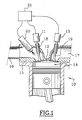
- FIG. 1 shows a cylinder 10 of an engine internal combustion four-stroke and the part of which upper forms a combustion chamber 12 delimited by a movable piston 14 and by a cylinder head 15.
- Cylinder 10 has multiple intake valves and several exhaust valves. We have represented a single intake valve 18 and single valve exhaust 19.
- the cylinder 10 is supplied with air / fuel mixture by an intake circuit 16 which opens into the combustion 12 through intake valves 18 whose movements are controlled by actuators linear electromagnetic 11 in order to shut off or not the communications between the intake circuit 16 and the chamber combustion 12.
- An exhaust circuit 17 is provided for evacuation gases burnt out of the combustion chamber 12 through exhaust valves 19 also controlled by electromagnetic linear actuators 13.
- Each valve is mounted on two springs (not roughly equivalent force, one tending to keep the valve in the closed position, the other tending to keep in the open position.
- the intake valve control 18 and exhaust 19 is provided by an electronic unit control 21 which controls the actuators 11, 13, and which also controls fuel injection, here indirect, at by means of an injector 20, as well as the ignition by means a candle (not shown).
- the electronic control unit 21 comprises in particular means for storing one or more engine operating maps, each of which determines the different engine parameters and states for a range of operating points, particularly with a view to determine the engine speed, the load each cylinder, etc.
- the electronic control unit 21 receives signals representative of operating parameters such as the engine speed, atmospheric pressure, pressure in each cylinder, the flow of intake gases and / or exhaust, instantaneous torque supplied, etc.
- the electronic control unit 21 analyzes in particular electrical characteristics representative of the correct operation of the actuators 11, 13.
- the shape of the current curve supplying an actuator changes significantly, depending on the valve movement dynamics, with differences depending on the direction of travel.
- This special feature is operated by the electronic control unit 21 to detect the failure of a valve which, under the action of the two springs, remains open in the balance position at mid-stroke.
- electronic control unit 21 analysis of the displacement measurements of the valves or actuators 11, 13.
- the piston 14 performs a descending race from top dead center TDC to point dead low PMB and then it does an upward run of the point low dead PMB towards top dead center TDC.
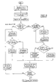
- the electronic control unit 21 If the electronic control unit 21 detects the failure of a valve, it controls the actuators 11, 13, the injector 20 and the spark plug, so as to compensate for this failure.
- the management of these elements aims to prevent the appearance of combustion or make the latter little energetic.
- the electronic control unit 21 As soon as the electronic control unit 21 detects the failure of an intake valve 18, it controls, on the offending cylinder, the cut off of the fuel supply, and switching off the ignition if the engine is fitted with a compatible ignition device.
- compatible ignition device is meant that the ignition device includes an ignition coil cylinder, or else it has an ignition coil for two cylinders but also that the operating cycles of each of these two cylinders are offset by one turn crankshaft.
- the electronic control unit determines the risk of combustion.
- the risk of combustion is effective if ignition could not be turned off, or if a hot spot is capable to initiate combustion.
- the electronic control unit 21 considers that the ignition and power cuts are sufficient to prevent combustion.
- the electronic control unit 21 controls the cylinder operation in a first degraded mode MD1.
- the first degraded mode MD1 consists on the one hand in keep the exhaust valves 19 closed, and on the other hand, to order either the opening or the closing, valid intake valves 18. We also maintain ignition and fuel supply cuts.
- the closure of the exhaust valves 19 aims to avoid any fresh air supply to the circuit exhaust 17.
- control electronics 21 identifies the position in which is the piston 14.
- valve failure has been detected 18 when it is closed, the piston 14 is then in its downstroke, or near the bottom dead center PMB.
- the unit control electronics 21 then command, as soon as possible possible, the closing of the valid inlet valves 18 and opening the exhaust valves 19.
- This command is to limit the admission of carburetted charge, by closing the intake valves 18 valid, and to dilute the charge admitted by burnt gases introduced by opening the exhaust valves 19.
- the combustion chamber 12 is thus filled with a mixture of air and exhaust gases, with a very strong proportion of these. The mixture is very little combustible.
- either the unit control electronics 21 When the piston 14 is near the point dead low PMB or in its upward stroke, either the unit control electronics 21 then holds the valves exhaust 19 open, i.e. the electronic unit of command 21 controls the closing of the valves exhaust 19.
- valves are closed exhaust 19 if you want to avoid pushing back the load unburned to the exhaust circuit 17. We act of this way, for example if it is feared that the charge will burn at level of a catalyst (not shown) located at the outlet of the exhaust circuit 17 and that it does not damage it.
- the unit control electronics 21 launches discount program in motion of the faulty valve. During this program, the exhaust valves 19 remain closed and the valid intake valves 18 remain open.
- Restoration programs of a valve are known. We can for example excite again electrically the actuator of the faulty valve.
- the electronic unit 21 controls the resumption of operation normal from cylinder 10 to the next synchronization signal with the other cylinders.
- the unit control electronics 21 controls the operation of the cylinder 10 according to the first degraded mode MD1 until the faulty valve is working again.
- the electronic control unit 21 As soon as the electronic control unit 21 detects the failure of an exhaust valve 19, it controls the cut off the fuel supply, and cut off ignition if the engine is fitted with an ignition device compatible.
- This step of the process is identical to that implemented operates in the case of a faulty intake valve 18.
- the electronic control unit 21 then identifies the position in which the intake valves are located 18.
- the electronic control unit 21 controls the operation of the cylinder 10 according to a second degraded mode MD2.
- This degraded mode MD2 corresponds to an operation in which the intake valves 18 are closed and the 19 valid exhaust valves are open.
- unit 21 controls the closing of the intake valves 18 the most as early as possible.
- the electronic control unit 21 controls the most as soon as possible, the closing of the intake valves 18 and the opening of the valid exhaust valves 19. Then, during the upward stroke of the piston 14, the electronic unit 21 keeps the exhaust valves 19 valid open.
- the unit control electronics 21 launches discount program in motion of the faulty valve. During this program, the intake valves 18 remain closed and the 19 valid exhaust valves remain open.
- the electronic unit 21 controls the resumption of operation normal from cylinder 10 to the next synchronization signal with the other cylinders.
- the unit control electronics 21 controls the operation of the cylinder 10 according to the second degraded mode MD2 until the faulty valve is working again.
- At least one valve remains open, so that the flows and pressures in cylinder 10 do not do not, or only slightly, disturb the oscillations of resetting faulty valve movement.
- the method according to the invention also makes it possible to ensure a diagnostic function since, when the failure of a valve on cylinder 10, we can advise the user to perform a mechanical examination, for example by lighting an alert light on the dashboard.
Landscapes
- Engineering & Computer Science (AREA)
- Mechanical Engineering (AREA)
- General Engineering & Computer Science (AREA)
- Chemical & Material Sciences (AREA)
- Combustion & Propulsion (AREA)
- Physics & Mathematics (AREA)
- Electromagnetism (AREA)
- Output Control And Ontrol Of Special Type Engine (AREA)
- Electrical Control Of Air Or Fuel Supplied To Internal-Combustion Engine (AREA)
- Valve Device For Special Equipments (AREA)
Applications Claiming Priority (2)
| Application Number | Priority Date | Filing Date | Title |
|---|---|---|---|
| FR9909230A FR2796421B1 (fr) | 1999-07-16 | 1999-07-16 | Procede de commande d'un moteur a combustion en vue de compenser la defaillance d'une soupape |
| FR9909230 | 1999-07-16 |
Publications (2)
| Publication Number | Publication Date |
|---|---|
| EP1069298A1 true EP1069298A1 (de) | 2001-01-17 |
| EP1069298B1 EP1069298B1 (de) | 2004-05-06 |
Family
ID=9548173
Family Applications (1)
| Application Number | Title | Priority Date | Filing Date |
|---|---|---|---|
| EP00401883A Expired - Lifetime EP1069298B1 (de) | 1999-07-16 | 2000-06-30 | Verfahren zur Steuerung eines Verbrennungsmotors um das Versagen eines Ventiles zu kompensieren |
Country Status (3)
| Country | Link |
|---|---|
| EP (1) | EP1069298B1 (de) |
| DE (1) | DE60010380T2 (de) |
| FR (1) | FR2796421B1 (de) |
Cited By (5)
| Publication number | Priority date | Publication date | Assignee | Title |
|---|---|---|---|---|
| EP1489272A3 (de) * | 2003-06-17 | 2006-02-08 | Toyota Jidosha Kabushiki Kaisha | Vorrichtung und Verfahren für variable Ventilsteuerung |
| EP1426599A4 (de) * | 2001-09-14 | 2009-05-06 | Honda Motor Co Ltd | Störungsdetektor für fahrzeug mit verzögerungs/leerlauf-zylinder-motor |
| US7623328B2 (en) | 2004-02-03 | 2009-11-24 | Hitachi, Ltd. | Driving control apparatus for motion mechanism and control method of driving control apparatus |
| EP1611330A4 (de) * | 2003-01-22 | 2010-06-16 | Abraham E Karem | Ausfalltoleranter verbrennungsmotor |
| US11624335B2 (en) | 2021-01-11 | 2023-04-11 | Tula Technology, Inc. | Exhaust valve failure diagnostics and management |
Families Citing this family (1)
| Publication number | Priority date | Publication date | Assignee | Title |
|---|---|---|---|---|
| US11635349B1 (en) | 2021-11-30 | 2023-04-25 | Honda Motor Co., Ltd. | Valve testing apparatus |
Citations (5)
| Publication number | Priority date | Publication date | Assignee | Title |
|---|---|---|---|---|
| JPS61247843A (ja) * | 1985-04-25 | 1986-11-05 | Masashi Yamakawa | 電子制御式内燃機関の動弁監視安全装置 |
| EP0493634A1 (de) * | 1989-12-12 | 1992-07-08 | Isuzu Ceramics Research Institute Co., Ltd. | Elektromagnetisches Ventilsteuersystem |
| US5190013A (en) * | 1992-01-10 | 1993-03-02 | Siemens Automotive L.P. | Engine intake valve selective deactivation system and method |
| JPH05187335A (ja) * | 1992-01-08 | 1993-07-27 | Nippondenso Co Ltd | 内燃機関の吸気制御装置 |
| EP0777038A2 (de) * | 1995-01-27 | 1997-06-04 | Honda Giken Kogyo Kabushiki Kaisha | Steuervorrichtung für Brennkraftmaschinen |
-
1999
- 1999-07-16 FR FR9909230A patent/FR2796421B1/fr not_active Expired - Fee Related
-
2000
- 2000-06-30 EP EP00401883A patent/EP1069298B1/de not_active Expired - Lifetime
- 2000-06-30 DE DE60010380T patent/DE60010380T2/de not_active Expired - Fee Related
Patent Citations (5)
| Publication number | Priority date | Publication date | Assignee | Title |
|---|---|---|---|---|
| JPS61247843A (ja) * | 1985-04-25 | 1986-11-05 | Masashi Yamakawa | 電子制御式内燃機関の動弁監視安全装置 |
| EP0493634A1 (de) * | 1989-12-12 | 1992-07-08 | Isuzu Ceramics Research Institute Co., Ltd. | Elektromagnetisches Ventilsteuersystem |
| JPH05187335A (ja) * | 1992-01-08 | 1993-07-27 | Nippondenso Co Ltd | 内燃機関の吸気制御装置 |
| US5190013A (en) * | 1992-01-10 | 1993-03-02 | Siemens Automotive L.P. | Engine intake valve selective deactivation system and method |
| EP0777038A2 (de) * | 1995-01-27 | 1997-06-04 | Honda Giken Kogyo Kabushiki Kaisha | Steuervorrichtung für Brennkraftmaschinen |
Non-Patent Citations (2)
| Title |
|---|
| PATENT ABSTRACTS OF JAPAN vol. 011, no. 098 (M - 575) 27 March 1987 (1987-03-27) * |
| PATENT ABSTRACTS OF JAPAN vol. 017, no. 612 (M - 1509) 11 November 1993 (1993-11-11) * |
Cited By (6)
| Publication number | Priority date | Publication date | Assignee | Title |
|---|---|---|---|---|
| EP1426599A4 (de) * | 2001-09-14 | 2009-05-06 | Honda Motor Co Ltd | Störungsdetektor für fahrzeug mit verzögerungs/leerlauf-zylinder-motor |
| EP1611330A4 (de) * | 2003-01-22 | 2010-06-16 | Abraham E Karem | Ausfalltoleranter verbrennungsmotor |
| EP1489272A3 (de) * | 2003-06-17 | 2006-02-08 | Toyota Jidosha Kabushiki Kaisha | Vorrichtung und Verfahren für variable Ventilsteuerung |
| US7623328B2 (en) | 2004-02-03 | 2009-11-24 | Hitachi, Ltd. | Driving control apparatus for motion mechanism and control method of driving control apparatus |
| US11624335B2 (en) | 2021-01-11 | 2023-04-11 | Tula Technology, Inc. | Exhaust valve failure diagnostics and management |
| US11959432B2 (en) | 2021-01-11 | 2024-04-16 | Tula Technology, Inc. | Exhaust valve failure diagnostics and management |
Also Published As
| Publication number | Publication date |
|---|---|
| DE60010380D1 (de) | 2004-06-09 |
| FR2796421B1 (fr) | 2001-10-05 |
| DE60010380T2 (de) | 2005-03-17 |
| EP1069298B1 (de) | 2004-05-06 |
| FR2796421A1 (fr) | 2001-01-19 |
Similar Documents
| Publication | Publication Date | Title |
|---|---|---|
| FR2779476A1 (fr) | Moteur a combustion interne avec calage variable de l'arbre a cames et masquage de la soupape d'admission | |
| FR2884855A1 (fr) | Systeme de soupapes a commande variable pour un moteur a allumage par compression | |
| FR2661212A1 (fr) | Moteurs a combustion interne a cycle d'otto a dispositif de reglage des temps d'actionnement des soupapes d'admission. | |
| EP1074713A1 (de) | Verfahren zur Steuerung einer Brennkraftmaschine zur Erleichterung des Startes nach Abschalten | |
| FR2893676A1 (fr) | Procede pour controler l'admission et/ou l'echappement d'au moins un cylindre desactive d'un moteur a combustion interne | |
| EP1069298B1 (de) | Verfahren zur Steuerung eines Verbrennungsmotors um das Versagen eines Ventiles zu kompensieren | |
| WO2005113966A1 (fr) | Procede de commande de fonctionnement d'un groupe de cylindres d'un moteur a combustion interne | |
| FR2848251A1 (fr) | Dispositif de commande d'arret pour moteur a combustion interne | |
| EP2077382B1 (de) | Verfahren für den Kaltstart eines Verbrennungsmotors, insbesondere eines selbstzündenden Verbrennungsmotors, und Motor, welcher dieses Verfahren verwendet | |
| EP1544434A1 (de) | Verfahren zur Steuerung einer abgasturbogeladenen Brennkraftmaschine | |
| FR2916799A1 (fr) | Procede et dispositif de commande de soupape avec plusieurs phases de levee, procede d'alimentation d'un moteur | |
| WO2012085448A1 (fr) | Dispositif de commande d'un moteur thermique | |
| FR2885389A1 (fr) | Procede de reduction des emissions d'hydrocarbures d'un moteur froid et dispositif et moteur mettant en oeuvre ce procede | |
| EP1209341A1 (de) | Verfahren zur Steuerung eines Verbrennungsmotors zur Optimierung des Starts | |
| FR2869643A1 (fr) | Procede de commande du fonctionnement d'un cylindre de moteur a combustion interne | |
| FR2835569A1 (fr) | Procede et dispositif de commande d'une unite d'entrainement comprenant un moteur a combustion interne | |
| JP6048439B2 (ja) | エンジンの制御装置 | |
| FR2795133A1 (fr) | Procede de commande d'un moteur a combustion en vue de l'obtention d'un effet de frein moteur | |
| WO2012085450A1 (fr) | Procede de commande d'au moins une soupape d'admission d'un moteur thermique fonctionnant selon un cycle a quatre temps | |
| EP1163437B1 (de) | Methode für das regeln der leerlaufdrehzahl einer verbrennungsmaschine mit ventilen ohne nockenwellen | |
| EP1138885B1 (de) | Verfahren zur Kontrolle einer Brennkraftmaschine zur Erleichterung des Startes | |
| FR3107930A1 (fr) | Calculateur moteur et procédé de commande d’un moteur associé | |
| FR2807468A1 (fr) | Moteur a combustion interne equipe d'un mecanisme de commande de soupape electromagnetique et methode pour commander ce moteur | |
| EP2674601A1 (de) | Verfahren zur Spülung der Restabgase durch doppelten Ventilhub für einen Zweitaktmotor, insbesondere vom Dieseltyp | |
| FR2872860A1 (fr) | Procede ameliore de commande d'un moteur a combustion interne, en vue de diminuer les emissions de polluants, moteur fonctionnant selon un tel procede, et vehicule automobile equipe d'un tel moteur |
Legal Events
| Date | Code | Title | Description |
|---|---|---|---|
| PUAI | Public reference made under article 153(3) epc to a published international application that has entered the european phase |
Free format text: ORIGINAL CODE: 0009012 |
|
| AK | Designated contracting states |
Kind code of ref document: A1 Designated state(s): BE DE |
|
| AX | Request for extension of the european patent |
Free format text: AL;LT;LV;MK;RO;SI |
|
| 17P | Request for examination filed |
Effective date: 20010622 |
|
| AKX | Designation fees paid |
Free format text: BE DE |
|
| RAP1 | Party data changed (applicant data changed or rights of an application transferred) |
Owner name: RENAULT S.A.S. |
|
| GRAP | Despatch of communication of intention to grant a patent |
Free format text: ORIGINAL CODE: EPIDOSNIGR1 |
|
| GRAS | Grant fee paid |
Free format text: ORIGINAL CODE: EPIDOSNIGR3 |
|
| GRAA | (expected) grant |
Free format text: ORIGINAL CODE: 0009210 |
|
| AK | Designated contracting states |
Kind code of ref document: B1 Designated state(s): BE DE |
|
| REF | Corresponds to: |
Ref document number: 60010380 Country of ref document: DE Date of ref document: 20040609 Kind code of ref document: P |
|
| PG25 | Lapsed in a contracting state [announced via postgrant information from national office to epo] |
Ref country code: BE Free format text: LAPSE BECAUSE OF NON-PAYMENT OF DUE FEES Effective date: 20040630 |
|
| PGFP | Annual fee paid to national office [announced via postgrant information from national office to epo] |
Ref country code: DE Payment date: 20041230 Year of fee payment: 5 |
|
| BERE | Be: lapsed |
Owner name: RENAULT S.A.S. Effective date: 20040630 |
|
| PLBE | No opposition filed within time limit |
Free format text: ORIGINAL CODE: 0009261 |
|
| STAA | Information on the status of an ep patent application or granted ep patent |
Free format text: STATUS: NO OPPOSITION FILED WITHIN TIME LIMIT |
|
| 26N | No opposition filed |
Effective date: 20050208 |
|
| PG25 | Lapsed in a contracting state [announced via postgrant information from national office to epo] |
Ref country code: DE Free format text: LAPSE BECAUSE OF NON-PAYMENT OF DUE FEES Effective date: 20060103 |