EP1069293A2 - Engine operated machine - Google Patents
Engine operated machine Download PDFInfo
- Publication number
- EP1069293A2 EP1069293A2 EP00305911A EP00305911A EP1069293A2 EP 1069293 A2 EP1069293 A2 EP 1069293A2 EP 00305911 A EP00305911 A EP 00305911A EP 00305911 A EP00305911 A EP 00305911A EP 1069293 A2 EP1069293 A2 EP 1069293A2
- Authority
- EP
- European Patent Office
- Prior art keywords
- engine
- shroud
- case
- carrying handle
- cover
- Prior art date
- Legal status (The legal status is an assumption and is not a legal conclusion. Google has not performed a legal analysis and makes no representation as to the accuracy of the status listed.)
- Granted
Links
- 238000001816 cooling Methods 0.000 claims description 34
- 238000013016 damping Methods 0.000 claims description 6
- 239000000463 material Substances 0.000 abstract description 5
- 239000000446 fuel Substances 0.000 description 25
- 239000002828 fuel tank Substances 0.000 description 15
- 230000003014 reinforcing effect Effects 0.000 description 14
- 238000012423 maintenance Methods 0.000 description 7
- 239000007858 starting material Substances 0.000 description 7
- XAGFODPZIPBFFR-UHFFFAOYSA-N aluminium Chemical compound [Al] XAGFODPZIPBFFR-UHFFFAOYSA-N 0.000 description 3
- 229910052782 aluminium Inorganic materials 0.000 description 3
- 238000004512 die casting Methods 0.000 description 3
- 238000000034 method Methods 0.000 description 3
- 229920003002 synthetic resin Polymers 0.000 description 3
- 239000000057 synthetic resin Substances 0.000 description 3
- 238000005452 bending Methods 0.000 description 2
- 238000007599 discharging Methods 0.000 description 2
- 230000000694 effects Effects 0.000 description 2
- 230000002093 peripheral effect Effects 0.000 description 2
- 230000000903 blocking effect Effects 0.000 description 1
- 230000003247 decreasing effect Effects 0.000 description 1
- 230000010349 pulsation Effects 0.000 description 1
- 230000035939 shock Effects 0.000 description 1
- 238000009423 ventilation Methods 0.000 description 1
Images


Classifications
-
- F—MECHANICAL ENGINEERING; LIGHTING; HEATING; WEAPONS; BLASTING
- F16—ENGINEERING ELEMENTS AND UNITS; GENERAL MEASURES FOR PRODUCING AND MAINTAINING EFFECTIVE FUNCTIONING OF MACHINES OR INSTALLATIONS; THERMAL INSULATION IN GENERAL
- F16M—FRAMES, CASINGS OR BEDS OF ENGINES, MACHINES OR APPARATUS, NOT SPECIFIC TO ENGINES, MACHINES OR APPARATUS PROVIDED FOR ELSEWHERE; STANDS; SUPPORTS
- F16M3/00—Portable or wheeled frames or beds, e.g. for emergency power-supply aggregates, compressor sets
-
- F—MECHANICAL ENGINEERING; LIGHTING; HEATING; WEAPONS; BLASTING
- F02—COMBUSTION ENGINES; HOT-GAS OR COMBUSTION-PRODUCT ENGINE PLANTS
- F02B—INTERNAL-COMBUSTION PISTON ENGINES; COMBUSTION ENGINES IN GENERAL
- F02B75/00—Other engines
- F02B75/16—Engines characterised by number of cylinders, e.g. single-cylinder engines
-
- F—MECHANICAL ENGINEERING; LIGHTING; HEATING; WEAPONS; BLASTING
- F02—COMBUSTION ENGINES; HOT-GAS OR COMBUSTION-PRODUCT ENGINE PLANTS
- F02B—INTERNAL-COMBUSTION PISTON ENGINES; COMBUSTION ENGINES IN GENERAL
- F02B63/00—Adaptations of engines for driving pumps, hand-held tools or electric generators; Portable combinations of engines with engine-driven devices
- F02B63/04—Adaptations of engines for driving pumps, hand-held tools or electric generators; Portable combinations of engines with engine-driven devices for electric generators
-
- F—MECHANICAL ENGINEERING; LIGHTING; HEATING; WEAPONS; BLASTING
- F02—COMBUSTION ENGINES; HOT-GAS OR COMBUSTION-PRODUCT ENGINE PLANTS
- F02B—INTERNAL-COMBUSTION PISTON ENGINES; COMBUSTION ENGINES IN GENERAL
- F02B77/00—Component parts, details or accessories, not otherwise provided for
- F02B77/11—Thermal or acoustic insulation
- F02B77/13—Acoustic insulation
-
- F—MECHANICAL ENGINEERING; LIGHTING; HEATING; WEAPONS; BLASTING
- F02—COMBUSTION ENGINES; HOT-GAS OR COMBUSTION-PRODUCT ENGINE PLANTS
- F02B—INTERNAL-COMBUSTION PISTON ENGINES; COMBUSTION ENGINES IN GENERAL
- F02B63/00—Adaptations of engines for driving pumps, hand-held tools or electric generators; Portable combinations of engines with engine-driven devices
- F02B63/04—Adaptations of engines for driving pumps, hand-held tools or electric generators; Portable combinations of engines with engine-driven devices for electric generators
- F02B63/044—Adaptations of engines for driving pumps, hand-held tools or electric generators; Portable combinations of engines with engine-driven devices for electric generators the engine-generator unit being placed on a frame or in an housing
- F02B2063/045—Frames for generator-engine sets
-
- F—MECHANICAL ENGINEERING; LIGHTING; HEATING; WEAPONS; BLASTING
- F02—COMBUSTION ENGINES; HOT-GAS OR COMBUSTION-PRODUCT ENGINE PLANTS
- F02B—INTERNAL-COMBUSTION PISTON ENGINES; COMBUSTION ENGINES IN GENERAL
- F02B63/00—Adaptations of engines for driving pumps, hand-held tools or electric generators; Portable combinations of engines with engine-driven devices
- F02B63/04—Adaptations of engines for driving pumps, hand-held tools or electric generators; Portable combinations of engines with engine-driven devices for electric generators
- F02B63/044—Adaptations of engines for driving pumps, hand-held tools or electric generators; Portable combinations of engines with engine-driven devices for electric generators the engine-generator unit being placed on a frame or in an housing
- F02B2063/046—Handles adapted therefor, e.g. handles or grips for movable units
-
- F—MECHANICAL ENGINEERING; LIGHTING; HEATING; WEAPONS; BLASTING
- F02—COMBUSTION ENGINES; HOT-GAS OR COMBUSTION-PRODUCT ENGINE PLANTS
- F02B—INTERNAL-COMBUSTION PISTON ENGINES; COMBUSTION ENGINES IN GENERAL
- F02B63/00—Adaptations of engines for driving pumps, hand-held tools or electric generators; Portable combinations of engines with engine-driven devices
- F02B63/04—Adaptations of engines for driving pumps, hand-held tools or electric generators; Portable combinations of engines with engine-driven devices for electric generators
- F02B63/044—Adaptations of engines for driving pumps, hand-held tools or electric generators; Portable combinations of engines with engine-driven devices for electric generators the engine-generator unit being placed on a frame or in an housing
- F02B63/048—Portable engine-generator combinations
Definitions
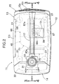
- a portable engine operated machine which includes an engine and a working device positioned in a case made of a synthetic resin, and designed so that it is carried by grasping a carrying handle provided at an upper portion of the case.
- the weight of the engine and the working device which are heavy members, are applied to a bottom of the case. For this reason, it is necessary to provide the case with sufficient rigidity to prevent the deformation of the case.
- the weight of the case is increased, resulting not only in an increase in weight of the entire engine operated machine, but also in a limited degree of design choice for the shape and the material of the case.
- an engine operated machine wherein a support formed integral with the head cover, is fixed to the carrying handle with a vibration-damping member positioned or interposed therebetween.
- the support formed integrally with the head cover is fixed to the carrying handle with the vibration-damping member interposed therebetween. Therefore, it is possible to reduce the vibration transmitted to the carrying handle.
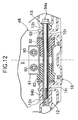
- Fig. 2 is a view taken along a line 2-2 in Fig. 1.
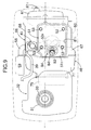
- Fig. 7 is a view taken along a line 7-7 in Fig. 5.
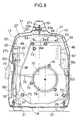
- Fig. 8 is a sectional view taken along a line 8-8 in Fig. 3.
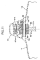
- Fig. 9 is a view taken in a direction of an arrow 9 in Fig. 3.
- Figs. 1 to 13 show an embodiment of the present invention.
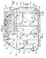
- the case 11 is provided at its front portion with a left reinforcing frame 26 and a right reinforcing frame 27, each of which is formed of FRP into an inverted L-shape.
- the left reinforcing frame 26 fixed at its lower end to a left side of the undercover 16 by a bolt 28, rises upwards and laterally inwards along an inner surface of the left side cover 12, and has an upward-folded mounting portion 26 1 formed at an upper end thereof.
- the fuel tank 32 is supported in such a manner that it is sandwiched from the left and right between the left and right side covers 12 and 13. Therefore, the fuel tank 32 can be demounted by only separating the left and right side covers 12 and 13 from each other without an operation such as detachment of the bolt. Moreover, since the fuel tank 32 is surrounded by the left and right reinforcing frames 26 and 27, the fuel tank 32 can be protected from a shock applied thereto from the outside. The left and right reinforcing frames 26 and 27 do not cover the entire engine generator and hence, a substantial increase in weight is not brought about.
- the fuel tank 32, the fuel pump 35, the fuel cock 36 and the like comprising a fuel supply system, are supported in a collected manner on the left and right reinforcing frames 26 and 27 rather than on the left and right side frames 12 and 13. Therefore, for the purpose of maintenance of the fuel supply system, the left and right side frames 12 and 13 can be removed easily.
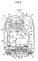
- a power generating unit 46 comprising the engine E and the generator G connected integrally to each other, will be described below with reference to Figs. 5 to 13.
- a shroud 66 made of a synthetic resin and covering the periphery of the engine E is divided into a left shroud half 67 and a right shroud half 68.
- the left shroud half 67 is fastened to left sides of the crankcase 48 and the cylinder block 49 of the engine E by two bolts 69, 69 (see Figs. 3 and 5)
- the right shroud half 68 is fastened to right sides of the crankcase 48 and the cylinder block 49 of the engine E by two bolts 70, 70 (see Figs. 4 and 5).
- the shroud 66 has front and rear surfaces which open.
- the outer periphery of the muffler 61 is fitted into the opening in the rear surface with a gap left therebetween, and a fan cover 71 made from aluminum by a die-casting process is fitted to cover the opening in the front surface.
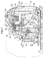
- the fan cover 71 covers the generator G and the cooling fan 57 and is fastened at its upper portion to the cylinder head 50 of the engine E by a bolt 72 and at its lower portion to the crankcase 48 of the engine E by two bolts 73, 73 (see Figs. 7 and 8).
- a recoil starter 75 is fixed to a central opening in the fan cover 71 by three bolts 74.
- the recoil starter 75 includes a reel 77 rotatably carried on a recoil starter cover 76, a cable 78 wound at one end thereof around the reel 77 and passing at the other end thereof through the right reinforcing frame 27 and the right cover 13, a control knob 79 mounted at the other end of the cable 78, and a driving member 80 mounted on the reel 77 and capable of being brought into and out of engagement with a driven member 57 1 integral with the cooling fan 57 (see Figs. 7 and 8).
- Cooling-air introducing ports 76 1 are defined in the recoil starter cover 76, and a cooling-air introducing port 64 is also defined between a lower end of the recoil starter cover 76 and a front lower portion of the shroud 66 (see Fig. 7).
- the driving member 80 actuated by a cam mechanism (not shown) can be brought into engagement with the driven member 57 1 to rotate the cooling fan 57, whereby the crankshaft 47 connected to the cooling fan 57 through the flywheel 55 can be cranked or rotated to start the engine E.
- the control knob is released, the driving member 80 is brought out of engagement with the driven member 57 1 , whereby the reel 77 is revered into the original position under the action of a return spring (not shown), while winding-up the cable 78 therearound.
- a rectangular opening 81 1 is defined, so that it is surrounded by the left shroud half 67, the right shroud half 68 and the fan cover 71, and the head cover 51 of the engine E passes through the opening 81 1 and protrudes to the outside of the shroud 66.
- An air baffle plate 51 1 is integrally formed at a front portion of the head cover 51 and extends in such a manner that it is inclined forward and downward.
- a space forming an air passage 82 is defined between the air baffle plate 51 1 and a notch 50 1 (see Fig. 9) defined in an upper surface of a front portion of the cylinder head 50.
- An opening in an upper end of the guide member 84 is closed by a detachable cap 84 1 .
- An ignition coil 65 is mounted at an upper end of the fan cover 71 in proximity to the spark plug 83.
- the guide member 84 faces the spark plug replacing lid 12 1 of the left side cover 12 (see Fig. 2) and hence, the maintenance of the spark plug 83 can be carried out through the spark plug attaching and detaching bore 51 2 only by opening the spark plug replacing lid 12 1 and removing the cap 4 1 .
- the maintenance of a valve operating mechanism covered with the head cover 51 e.g., the regulation of the tappet clearance and the like can be carried out easily, without removal of the left and right shroud halves 67 and 68, only by removing the head cover 51 exposed from the shroud 66.
- a longitudinally extending plate-shaped support 51 3 is projectingly provided on an upper surface of the head cover 51 of the engine.
- a pair of left and right rubber bushings 85, 85 are fitted into a circular support bore 51 4 centrally defined in the support 51 3 , and a collar 86 is inserted through the inside of the bushings 85, 85.
- a bolt 87a is inserted at a rear portion of the carrying handle 17 from the side of the left side cover 12 and fastened to an embedded nut 87b provided in the right side cover 13.
- Bosses 12 2 and 13 2 are projectingly provided on the inner surfaces of the left and right side covers 12 and 13 in the vicinity of the bolt 87a.
- Washers 88, 88 are disposed at ends of the left and right rubber bushings 85, 85, and in this state, a connecting pin 89 passing through the washers 88, 88 and the collar 86, is fitted at its opposite ends over the bosses 12 2 and 13 2 of the left and right side covers 12 and 13, respectively.
- a mounting bracket 91 is fixed to a rear lower portion of the crankcase 48 of the engine E by two bolts 90, 90.
- the mounting bracket 91 protrudes out of the opening 81 2 in the rear lower portion of the shroud 66, and a pair of left and right rubber bushings 92, 92 are fitted over the bracket 91.
- a pair of left and right mounting ribs 16 1 , 16 1 are formed on an upper surface of a rear portion of the undercover 16 of the case 11, and the rubber bushings 92, 92 are supported on an outer periphery of a central portion of a collar 93 bridging between the pair of mounting ribs 16 1 , 16 1 , with a pair of left and right washers 95, 95 interposed therebetween.
- the rear lower portion of the engine exposed from the shroud 66 is resiliently supported on the undercover 16 with the rubber bushings 92, 92 interposed therebetween by fastening a bolt 94a inserted from the boss 13 3 of the right side cover 13 and passing through the collar 93 to an embedded nut 94b provided in the boss 12 3 of the left side cover 12.
- a mounting bracket 71 1 is integrally formed at a lower portion of the fan cover 71 and resiliently supported through a bolt 94a on a pair of left and right mounting ribs 16 2 , 16 2 projectingly provided on an upper surface of a front portion of the undercover 16.
- the structure for supporting the mounting bracket 71 1 is the same as the structure for supporting the mounting bracket 91 described with reference to Fig. 5.
- the head cover 51 located on the upper side is resiliently supported on the carrying handle 17 through the rubber bushing 85, 85;
- the crankcase 48 located on the rear and lower side is resiliently supported on the undercover 16 through the rubber bushings 92, 92;
- the fan cover 71 located on the front and lower side is resiliently supported on the undercover 16 through the rubber bushings 92, 92. Therefore, the weight of the power-generating unit 46 can be dispersed to various portions of the case 11 to prevent a load from being concentrated on a small portion of the case 11.
- the vibration absorbing effect of the rubber bushings 85, 85 and 92 makes it possible not only to prevent the vibration of the engine E from being transmitted to the carrying handle 17, but also to prevent the case 11 from being resonant by the vibration of the engine E.
- the carrying handle 17 when the carrying handle 17 is lifted to carry the engine generator, most of the weight of the power generating unit 46 including the engine E and the generator G is supported from the support 51 3 of the head cover 51 via the rubber bushings 85, 85, the connecting pin 89 and the bosses 12 2 and 13 2 onto the carrying handle 17 of the case 11. Namely, the power-generating unit 46 is brought into a state in which it hangs down on the carrying handle 17, and thus, it is not necessary to support the weight of the power-generating unit 46 by the case 11 itself. Therefore, the thickness of the case 11 connected below the carrying handle 17 can be reduced, thereby not only providing a reduction in weight of the power-generating unit 46, but also providing a substantial increase in degree of freedom of the design such as the shape and the material of the case 11.
- the entire height of the engine generator can be kept to a low level, as compared with a case where the head cover 51 is covered completely with the shroud 66, and the shroud 66 is supported at its upper end on the carrying handle 17.
- the load can be dispersed to the front and rear of the carrying handle 17 without the bearing of the load by the left and right side covers 12 and 13, whereby the bending load applied to the carrying handle 17 and a portion of the case 11, in the vicinity of the carrying handle 17 can be alleviated, because the front portion of the undercover 16 supporting the lower portion of the power-generating unit 46, namely, the lower portion of the fan cover 71 and the lower portion of the crankcase 48, is connected to the front portion of the carrying handle 17 through the left and right reinforcing frames 26 and 27 each having a high rigidity.
- the fan cover 71 made from aluminum by a die-casting process, is fastened to the crankcase 48 and the cylinder head 50 in a blocking manner, and the mounting bracket 91 of the crankcase 48 protruding from the shroud 66 covering the outer periphery of the fan cover 71, the crankcase 48 and the cylinder head 50, and the mounting bracket 71 1 of the fan cover 71, are supported on the mounting ribs 16 1 , 16 1 ; 16 2 , 16 2 of the undercover 16 through the rubber bushings 92, 92. Therefore, the power-generating unit 46 can be supported reliably on the undercover 16 without a special support member such as an engine bed.
- the left and right side covers 12 and 13 can be separated from the undercover 16 by only removing the four bolts 30a, 87a, 94a, 94a. Therefore, the engine E and the generator G can be exposed without moving the engine generator sideways, whereby the maintenance thereof can be carried out easily.
- the generator G corresponds to a working device of the present invention
- the rubber bushing 85 corresponds to a vibration-damping member of the present invention.
- the cooling fan 57 mounted on the flywheel 55 of the generator G is rotated within the shroud 66.
- external air passes through the cooling-air introducing ports 14 1 and 14 2 (see Figs. 3 and 4) in the front cover 14 and is introduced as cooling air into the case 11.
- Reference character 14 3 is a guide for the cooling air introduced through cooling-air introducing port 14 2 .
- the cooling air is introduced through the cooling-air introducing ports 76 1 defined in the recoil starter cover 76 and the cooling-air introducing port 64 defined below the recoil starter cover 76 into the fan cover 71 and the shroud 66 to cool the generator G, the engine E and the muffler 61 accommodated in the shroud 66. Thereafter, the cooling air passes through the gap between the shroud 66 and the muffler 61 and is discharged through the cooling-air discharge port 15 2 to the outside of the case 11. Openings 96 (see Fig. 7) are defined in the flywheel 55 and the cooling fan 57, and the air heated within the generator G is drawn through the openings 96 into the shroud 66.
- the flow of the cooling air within the shroud 66 can be smoothed to enhance the cooling effect, because the air baffle plate 51 1 formed integrally on the head cover 51 of the engine E, defines the air passage 82 by cooperation with the fan cover 71 and the left and right shroud halves 67 and 68. Moreover, the cooling air flows directly through the inside of the fan cover 71 made from aluminum by the die-casting process and is coupled to the engine E and hence, the fan cover 71 exhibits a heat sink function to enhance the performance of cooling the engine E.
- the cooling air flows substantially rectilinearly from the front to the rear within the case 11, it cools the generator G which is a heat-generating member, the engine E and the muffler 61. Therefore, it is possible not only to keep the resistance to the flow of the cooling air to enhance the cooling efficiency, but also to keep the number of the cooling fans 57 to one, to reduce the number of parts. Noises emitted by the engine E and the cooling fan 57 are reduced effectively by the shroud 66 and the case 11 which doubly covers the engine E and the cooling fan 57, thereby enabling the quiet operation of the engine generator.
- the generator G has been illustrated as the working device in the above-described embodiment, but the present invention is applicable to other working devices such as a compressor, a pump and the like.
- the rubber bushings 85, 85 have been illustrated as resilient members in the embodiment, but another resilient member such as a spring and the like may be employed.
- the carrying handle 17 has been formed as a portion of the case 11 in the embodiment, but the carrying handle 17 may be formed of another member and attached to the case 11.
Landscapes
- Engineering & Computer Science (AREA)
- General Engineering & Computer Science (AREA)
- Mechanical Engineering (AREA)
- Chemical & Material Sciences (AREA)
- Combustion & Propulsion (AREA)
- Acoustics & Sound (AREA)
- Physics & Mathematics (AREA)
- Motor Or Generator Frames (AREA)
- Ignition Installations For Internal Combustion Engines (AREA)
- Soil Working Implements (AREA)
- Led Device Packages (AREA)
- Multi-Conductor Connections (AREA)
- Connection Of Motors, Electrical Generators, Mechanical Devices, And The Like (AREA)
Abstract
Description
Claims (5)
- An engine operated machine comprising a case having a carrying handle on the upper portion thereof, an engine having a shroud mounted thereon for guiding cooling-air, and a working device connected integrally to said engine and driven by said engine, said engine and said working device being positioned in said case, wherein said engine includes a crankcase, a cylinder block and a cylinder head covered with said shroud, and a head cover exposed through an opening defined in an upper portion of said shroud, said head cover being fixed to said carrying handle.
- An engine operated machine according to Claim 1, further including a support formed integrally with said head cover and fixed to said carrying handle, and a vibration-damping member interposed between said support and said carrying handle.
- An engine operated machine according to Claim 1 or 2, further including an air baffle plate integrally formed with said head cover, said air baffle plate defining an air passage with said shroud, said air baffle plate having a spark plug attaching and detaching bore defined therein for providing access for the attachment and detachment of a spark plug of said engine.
- An engine operated machine according to any one of Claims 1 to 3, wherein said head cover can be attached and detached from the outside of said shroud with said shroud remaining mounted on said engine.
- An engine operated machine according to any one of Claims 1 to 4, further including a cooling fan mounted on said working device, wherein said working device is a generator, and the cooling air introduced into said case by said cooling fan mounted on said generator cools said generator, said engine and a muffler, and is discharged to the outside of said case.
Priority Applications (1)
| Application Number | Priority Date | Filing Date | Title |
|---|---|---|---|
| EP04010480A EP1441115B1 (en) | 1999-07-12 | 2000-07-12 | Engine operated machine |
Applications Claiming Priority (2)
| Application Number | Priority Date | Filing Date | Title |
|---|---|---|---|
| JP19782899A JP3754579B2 (en) | 1999-07-12 | 1999-07-12 | Engine working machine |
| JP19782899 | 1999-07-12 |
Related Child Applications (1)
| Application Number | Title | Priority Date | Filing Date |
|---|---|---|---|
| EP04010480.4 Division-Into | 2004-05-03 |
Publications (3)
| Publication Number | Publication Date |
|---|---|
| EP1069293A2 true EP1069293A2 (en) | 2001-01-17 |
| EP1069293A3 EP1069293A3 (en) | 2002-03-20 |
| EP1069293B1 EP1069293B1 (en) | 2004-09-29 |
Family
ID=16381027
Family Applications (2)
| Application Number | Title | Priority Date | Filing Date |
|---|---|---|---|
| EP04010480A Expired - Lifetime EP1441115B1 (en) | 1999-07-12 | 2000-07-12 | Engine operated machine |
| EP00305911A Expired - Lifetime EP1069293B1 (en) | 1999-07-12 | 2000-07-12 | Engine operated machine |
Family Applications Before (1)
| Application Number | Title | Priority Date | Filing Date |
|---|---|---|---|
| EP04010480A Expired - Lifetime EP1441115B1 (en) | 1999-07-12 | 2000-07-12 | Engine operated machine |
Country Status (7)
| Country | Link |
|---|---|
| US (1) | US6378468B1 (en) |
| EP (2) | EP1441115B1 (en) |
| JP (1) | JP3754579B2 (en) |
| KR (1) | KR100348872B1 (en) |
| CN (4) | CN100504051C (en) |
| DE (2) | DE60024152T2 (en) |
| TW (1) | TW432162B (en) |
Cited By (6)
| Publication number | Priority date | Publication date | Assignee | Title |
|---|---|---|---|---|
| EP1707776A4 (en) * | 2003-10-28 | 2012-08-08 | Henglin Xiao | A cooling system of an engine for the inside of a generator |
| EP3219951A1 (en) * | 2016-03-15 | 2017-09-20 | Honda Motor Co., Ltd. | Engine-driven working machine |
| EP3219953A1 (en) * | 2016-03-16 | 2017-09-20 | Honda Motor Co., Ltd. | Engine-driven working machine |
| CN114483294A (en) * | 2022-01-11 | 2022-05-13 | 重庆乾威科技有限公司 | Tool type generator handle |
| WO2024011292A1 (en) * | 2022-07-15 | 2024-01-18 | Duluxgroup (Australia) Pty Ltd | Motor guard |
| CN117569914A (en) * | 2023-11-20 | 2024-02-20 | 江苏江淮动力有限公司 | Energy-saving engine unit |
Families Citing this family (40)
| Publication number | Priority date | Publication date | Assignee | Title |
|---|---|---|---|---|
| JP3886002B2 (en) | 2002-03-27 | 2007-02-28 | ヤマハ発動機株式会社 | Engine generator |
| US6857410B2 (en) * | 2002-08-12 | 2005-02-22 | Tecumseh Products Co | Engine control system |
| CN1815001A (en) * | 2006-03-08 | 2006-08-09 | 无锡开普动力有限公司 | Portable generator |
| USD567175S1 (en) | 2006-08-25 | 2008-04-22 | Briggs & Stratton Corporation | Inverter generator |
| US7492050B2 (en) * | 2006-10-24 | 2009-02-17 | Briggs & Stratton Corporation | Cooling system for a portable generator |
| US7559297B2 (en) * | 2007-08-17 | 2009-07-14 | Yunfeng Ma | Portable Engine |
| US7699027B2 (en) * | 2007-08-17 | 2010-04-20 | Yunfeng Ma | Portable generator |
| JP5134428B2 (en) * | 2008-05-07 | 2013-01-30 | ヤンマー株式会社 | Arrangement structure of control box and power converter in package storage type engine generator |
| CN101392682A (en) * | 2008-10-16 | 2009-03-25 | 无锡开普动力有限公司 | Portable DC charging electric generator |
| US8122866B2 (en) * | 2008-10-29 | 2012-02-28 | GM Global Technology Operations LLC | Acoustic bumpers with engine front cover hidden mounting |
| JP5555522B2 (en) * | 2010-03-29 | 2014-07-23 | 本田技研工業株式会社 | Handheld work machine |
| JP5460535B2 (en) * | 2010-09-22 | 2014-04-02 | 株式会社マキタ | Thermal insulation spacer |
| CN102108897A (en) * | 2011-04-15 | 2011-06-29 | 周歆焱 | Portable general generator |
| AU2012216658B2 (en) | 2011-09-13 | 2016-09-15 | Black & Decker Inc | Method of reducing air compressor noise |
| US8899378B2 (en) | 2011-09-13 | 2014-12-02 | Black & Decker Inc. | Compressor intake muffler and filter |
| JP5840577B2 (en) * | 2012-07-30 | 2016-01-06 | 本田技研工業株式会社 | Portable engine generator |
| JP5697698B2 (en) * | 2013-03-05 | 2015-04-08 | 富士重工業株式会社 | Engine mount structure for engine-equipped equipment |
| JP6138531B2 (en) * | 2013-03-18 | 2017-05-31 | 本田技研工業株式会社 | Internal combustion engine for generator |
| JP2015037392A (en) * | 2013-08-19 | 2015-02-26 | 日立工機株式会社 | Engine working machine |
| US10294858B2 (en) | 2013-08-29 | 2019-05-21 | Polaris Industries Inc. | Portable generator |
| CA2923368C (en) * | 2015-07-23 | 2018-01-16 | Webb Motor Works Ltd. | Flathead engine shroud for a small block engine |
| US11111913B2 (en) | 2015-10-07 | 2021-09-07 | Black & Decker Inc. | Oil lubricated compressor |
| JP6687432B2 (en) * | 2016-03-16 | 2020-04-22 | 本田技研工業株式会社 | Engine driven work machine |
| US10408116B2 (en) * | 2017-10-03 | 2019-09-10 | Polaris Industries Inc. | Snowmobile |
| EP3693569B1 (en) * | 2017-12-11 | 2022-04-20 | Honda Motor Co., Ltd. | Engine device |
| WO2019187083A1 (en) * | 2018-03-30 | 2019-10-03 | 本田技研工業株式会社 | General purpose engine |
| JP2020108318A (en) * | 2018-12-28 | 2020-07-09 | 本田技研工業株式会社 | Power generator |
| WO2020152755A1 (en) * | 2019-01-21 | 2020-07-30 | 本田技研工業株式会社 | Power generation device |
| CN109681342A (en) * | 2019-02-15 | 2019-04-26 | 重庆华世丹动力科技股份有限公司 | The full bag engine of input type |
| CN113653564B (en) * | 2021-09-17 | 2022-05-24 | 浙江派尼尔科技股份有限公司 | Single-cylinder air-cooled diesel engine |
| US12398667B2 (en) | 2021-09-28 | 2025-08-26 | Honda Motor Co., Ltd. | Generator |
| CN115059543A (en) * | 2022-06-17 | 2022-09-16 | 北京理工大学 | Integrated multistage voltage mode auxiliary engine power station system |
| CN115059542A (en) * | 2022-06-17 | 2022-09-16 | 北京理工大学 | Integrated high-efficiency auxiliary power station system |
| USD1085006S1 (en) | 2023-10-11 | 2025-07-22 | Northern Tool & Equipment Company, Inc. | Generator assembly |
| USD1085009S1 (en) | 2023-10-11 | 2025-07-22 | Northern Tool & Equipment Company, Inc. | Generator assembly |
| USD1085008S1 (en) | 2023-10-11 | 2025-07-22 | Northern Tool & Equipment Company, Inc. | Generator assembly |
| USD1085010S1 (en) | 2023-10-11 | 2025-07-22 | Northern Tool & Equipment Company, Inc. | Generator assembly |
| USD1085012S1 (en) | 2023-10-11 | 2025-07-22 | Northern Tool & Equipment Company, Inc. | Generator assembly |
| USD1085011S1 (en) | 2023-10-11 | 2025-07-22 | Northern Tool & Equipment Company, Inc. | Generator assembly |
| USD1085007S1 (en) | 2023-10-11 | 2025-07-22 | Northern Tool & Equipment Company, Inc. | Generator assembly |
Citations (1)
| Publication number | Priority date | Publication date | Assignee | Title |
|---|---|---|---|---|
| JPS6421399A (en) | 1987-06-18 | 1989-01-24 | Westinghouse Electric Corp | Fuel rod takeoff apparatus, withdrawal of fuel rod, capacity reducer, use of extrusion rod and transfer of fuel rod |
Family Cites Families (10)
| Publication number | Priority date | Publication date | Assignee | Title |
|---|---|---|---|---|
| FR1329071A (en) * | 1962-04-27 | 1963-06-07 | Vap S A | Improvements to two-stroke engines for mopeds and other similar vehicles |
| US4550794A (en) * | 1981-01-14 | 1985-11-05 | Honda Giken Kogyo Kabushiki Kaisha | Motorcycle having an engine with a supercharger |
| JPS6140425A (en) * | 1984-07-31 | 1986-02-26 | Yanmar Diesel Engine Co Ltd | Case containing type engine generator |
| JPH0128270Y2 (en) * | 1984-10-09 | 1989-08-29 | ||
| US4647835A (en) * | 1984-12-19 | 1987-03-03 | Kawasaki Jukogyo Kabushiki Kaisha | Portable generator |
| US4859886A (en) * | 1986-02-28 | 1989-08-22 | Honda Giken Kogyo Kabushiki Kaisha | Portable engine-operated electric generator |
| US4827147A (en) * | 1986-11-12 | 1989-05-02 | Honda Giken Kogyo Kabushiki Kaisha | Engine-powered portable working apparatus |
| US4907546A (en) * | 1987-12-02 | 1990-03-13 | Kubota Ltd. | Air-cooled type cooling system for engine working machine assembly |
| JP3531692B2 (en) * | 1995-02-28 | 2004-05-31 | 本田技研工業株式会社 | Attachment structure of vibration isolator to shroud |
| JP3678028B2 (en) * | 1998-11-26 | 2005-08-03 | スズキ株式会社 | Portable actuator with engine |
-
1999
- 1999-07-12 JP JP19782899A patent/JP3754579B2/en not_active Expired - Lifetime
-
2000
- 2000-07-10 US US09/613,278 patent/US6378468B1/en not_active Expired - Lifetime
- 2000-07-10 KR KR1020000039305A patent/KR100348872B1/en not_active Expired - Lifetime
- 2000-07-11 TW TW089113776A patent/TW432162B/en not_active IP Right Cessation
- 2000-07-12 EP EP04010480A patent/EP1441115B1/en not_active Expired - Lifetime
- 2000-07-12 CN CNB2006100943379A patent/CN100504051C/en not_active Expired - Lifetime
- 2000-07-12 EP EP00305911A patent/EP1069293B1/en not_active Expired - Lifetime
- 2000-07-12 CN CNA2006100943398A patent/CN101016859A/en active Pending
- 2000-07-12 CN CN00120482A patent/CN1117922C/en not_active Expired - Lifetime
- 2000-07-12 DE DE60024152T patent/DE60024152T2/en not_active Expired - Lifetime
- 2000-07-12 DE DE60014264T patent/DE60014264T2/en not_active Expired - Lifetime
- 2000-07-12 CN CNB031410456A patent/CN1328491C/en not_active Expired - Lifetime
Patent Citations (1)
| Publication number | Priority date | Publication date | Assignee | Title |
|---|---|---|---|---|
| JPS6421399A (en) | 1987-06-18 | 1989-01-24 | Westinghouse Electric Corp | Fuel rod takeoff apparatus, withdrawal of fuel rod, capacity reducer, use of extrusion rod and transfer of fuel rod |
Cited By (10)
| Publication number | Priority date | Publication date | Assignee | Title |
|---|---|---|---|---|
| EP1707776A4 (en) * | 2003-10-28 | 2012-08-08 | Henglin Xiao | A cooling system of an engine for the inside of a generator |
| EP3219951A1 (en) * | 2016-03-15 | 2017-09-20 | Honda Motor Co., Ltd. | Engine-driven working machine |
| US10122245B2 (en) | 2016-03-15 | 2018-11-06 | Honda Motor Co., Ltd. | Engine-driven working machine |
| EP3219953A1 (en) * | 2016-03-16 | 2017-09-20 | Honda Motor Co., Ltd. | Engine-driven working machine |
| US10260456B2 (en) | 2016-03-16 | 2019-04-16 | Honda Motor Co., Ltd. | Engine-driven working machine |
| CN114483294A (en) * | 2022-01-11 | 2022-05-13 | 重庆乾威科技有限公司 | Tool type generator handle |
| CN114483294B (en) * | 2022-01-11 | 2024-01-23 | 重庆乾威科技有限公司 | A tool-type generator handle |
| WO2024011292A1 (en) * | 2022-07-15 | 2024-01-18 | Duluxgroup (Australia) Pty Ltd | Motor guard |
| CN117569914A (en) * | 2023-11-20 | 2024-02-20 | 江苏江淮动力有限公司 | Energy-saving engine unit |
| CN117569914B (en) * | 2023-11-20 | 2024-06-07 | 江苏江淮动力有限公司 | Energy-saving engine unit |
Also Published As
| Publication number | Publication date |
|---|---|
| CN1328491C (en) | 2007-07-25 |
| DE60024152D1 (en) | 2005-12-22 |
| CN1280244A (en) | 2001-01-17 |
| CN101016859A (en) | 2007-08-15 |
| CN101016858A (en) | 2007-08-15 |
| DE60014264T2 (en) | 2005-02-03 |
| DE60014264D1 (en) | 2004-11-04 |
| JP2001027127A (en) | 2001-01-30 |
| US6378468B1 (en) | 2002-04-30 |
| EP1069293A3 (en) | 2002-03-20 |
| EP1441115B1 (en) | 2005-11-16 |
| CN1515816A (en) | 2004-07-28 |
| CN100504051C (en) | 2009-06-24 |
| KR100348872B1 (en) | 2002-08-17 |
| EP1441115A1 (en) | 2004-07-28 |
| TW432162B (en) | 2001-05-01 |
| EP1069293B1 (en) | 2004-09-29 |
| CN1117922C (en) | 2003-08-13 |
| KR20010015264A (en) | 2001-02-26 |
| DE60024152T2 (en) | 2006-04-20 |
| JP3754579B2 (en) | 2006-03-15 |
Similar Documents
| Publication | Publication Date | Title |
|---|---|---|
| EP1069293B1 (en) | Engine operated machine | |
| EP1069295B1 (en) | Engine generating machine | |
| CA2529619C (en) | Engine-driven generator | |
| KR100652541B1 (en) | Engine Driven Work Tool | |
| JP4145912B2 (en) | Engine working machine | |
| CN111433444B (en) | Engine device | |
| JP3871829B2 (en) | Engine generator | |
| JP3754697B2 (en) | Engine working machine | |
| JP3585773B2 (en) | Engine generator | |
| JP4145911B2 (en) | Engine working machine | |
| JP4145899B2 (en) | Engine generator | |
| JP2004353677A5 (en) | ||
| JP2005282581A5 (en) |
Legal Events
| Date | Code | Title | Description |
|---|---|---|---|
| PUAI | Public reference made under article 153(3) epc to a published international application that has entered the european phase |
Free format text: ORIGINAL CODE: 0009012 |
|
| AK | Designated contracting states |
Kind code of ref document: A2 Designated state(s): AT BE CH CY DE DK ES FI FR GB GR IE IT LI LU MC NL PT SE Kind code of ref document: A2 Designated state(s): DE FR GB IT |
|
| AX | Request for extension of the european patent |
Free format text: AL;LT;LV;MK;RO;SI |
|
| PUAL | Search report despatched |
Free format text: ORIGINAL CODE: 0009013 |
|
| AK | Designated contracting states |
Kind code of ref document: A3 Designated state(s): AT BE CH CY DE DK ES FI FR GB GR IE IT LI LU MC NL PT SE |
|
| AX | Request for extension of the european patent |
Free format text: AL;LT;LV;MK;RO;SI |
|
| RIC1 | Information provided on ipc code assigned before grant |
Free format text: 7F 02B 63/02 A, 7F 02B 63/04 B |
|
| 17P | Request for examination filed |
Effective date: 20020529 |
|
| AKX | Designation fees paid |
Free format text: DE FR GB IT |
|
| GRAP | Despatch of communication of intention to grant a patent |
Free format text: ORIGINAL CODE: EPIDOSNIGR1 |
|
| GRAS | Grant fee paid |
Free format text: ORIGINAL CODE: EPIDOSNIGR3 |
|
| GRAA | (expected) grant |
Free format text: ORIGINAL CODE: 0009210 |
|
| AK | Designated contracting states |
Kind code of ref document: B1 Designated state(s): DE FR GB IT |
|
| REG | Reference to a national code |
Ref country code: GB Ref legal event code: FG4D |
|
| REG | Reference to a national code |
Ref country code: IE Ref legal event code: FG4D |
|
| REF | Corresponds to: |
Ref document number: 60014264 Country of ref document: DE Date of ref document: 20041104 Kind code of ref document: P |
|
| ET | Fr: translation filed | ||
| PLBE | No opposition filed within time limit |
Free format text: ORIGINAL CODE: 0009261 |
|
| STAA | Information on the status of an ep patent application or granted ep patent |
Free format text: STATUS: NO OPPOSITION FILED WITHIN TIME LIMIT |
|
| 26N | No opposition filed |
Effective date: 20050630 |
|
| REG | Reference to a national code |
Ref country code: FR Ref legal event code: PLFP Year of fee payment: 17 |
|
| REG | Reference to a national code |
Ref country code: FR Ref legal event code: PLFP Year of fee payment: 18 |
|
| REG | Reference to a national code |
Ref country code: FR Ref legal event code: PLFP Year of fee payment: 19 |
|
| PGFP | Annual fee paid to national office [announced via postgrant information from national office to epo] |
Ref country code: FR Payment date: 20190619 Year of fee payment: 20 |
|
| PGFP | Annual fee paid to national office [announced via postgrant information from national office to epo] |
Ref country code: DE Payment date: 20190702 Year of fee payment: 20 Ref country code: IT Payment date: 20190719 Year of fee payment: 20 |
|
| PGFP | Annual fee paid to national office [announced via postgrant information from national office to epo] |
Ref country code: GB Payment date: 20190710 Year of fee payment: 20 |
|
| REG | Reference to a national code |
Ref country code: DE Ref legal event code: R071 Ref document number: 60014264 Country of ref document: DE |
|
| REG | Reference to a national code |
Ref country code: GB Ref legal event code: PE20 Expiry date: 20200711 |
|
| PG25 | Lapsed in a contracting state [announced via postgrant information from national office to epo] |
Ref country code: GB Free format text: LAPSE BECAUSE OF EXPIRATION OF PROTECTION Effective date: 20200711 |