EP1069050B1 - Binding clip - Google Patents
Binding clip Download PDFInfo
- Publication number
- EP1069050B1 EP1069050B1 EP00115218A EP00115218A EP1069050B1 EP 1069050 B1 EP1069050 B1 EP 1069050B1 EP 00115218 A EP00115218 A EP 00115218A EP 00115218 A EP00115218 A EP 00115218A EP 1069050 B1 EP1069050 B1 EP 1069050B1
- Authority
- EP
- European Patent Office
- Prior art keywords
- binding clip
- receiving portion
- leg portions
- crossed
- engaging projections
- Prior art date
- Legal status (The legal status is an assumption and is not a legal conclusion. Google has not performed a legal analysis and makes no representation as to the accuracy of the status listed.)
- Expired - Lifetime
Links
- 239000013013 elastic material Substances 0.000 description 2
- 239000011347 resin Substances 0.000 description 2
- 229920005989 resin Polymers 0.000 description 2
- 230000001154 acute effect Effects 0.000 description 1
- 230000013011 mating Effects 0.000 description 1
- 238000003466 welding Methods 0.000 description 1
Images


Classifications
-
- B—PERFORMING OPERATIONS; TRANSPORTING
- B65—CONVEYING; PACKING; STORING; HANDLING THIN OR FILAMENTARY MATERIAL
- B65D—CONTAINERS FOR STORAGE OR TRANSPORT OF ARTICLES OR MATERIALS, e.g. BAGS, BARRELS, BOTTLES, BOXES, CANS, CARTONS, CRATES, DRUMS, JARS, TANKS, HOPPERS, FORWARDING CONTAINERS; ACCESSORIES, CLOSURES, OR FITTINGS THEREFOR; PACKAGING ELEMENTS; PACKAGES
- B65D33/00—Details of, or accessories for, sacks or bags
- B65D33/16—End- or aperture-closing arrangements or devices
- B65D33/1616—Elements constricting the neck of the bag
- B65D33/1625—Small plates or the like made of one piece and presenting slits or a central aperture to jam the neck of the bag
-
- B—PERFORMING OPERATIONS; TRANSPORTING
- B65—CONVEYING; PACKING; STORING; HANDLING THIN OR FILAMENTARY MATERIAL
- B65D—CONTAINERS FOR STORAGE OR TRANSPORT OF ARTICLES OR MATERIALS, e.g. BAGS, BARRELS, BOTTLES, BOXES, CANS, CARTONS, CRATES, DRUMS, JARS, TANKS, HOPPERS, FORWARDING CONTAINERS; ACCESSORIES, CLOSURES, OR FITTINGS THEREFOR; PACKAGING ELEMENTS; PACKAGES
- B65D69/00—Articles joined together for convenience of storage or transport without the use of packaging elements
-
- Y—GENERAL TAGGING OF NEW TECHNOLOGICAL DEVELOPMENTS; GENERAL TAGGING OF CROSS-SECTIONAL TECHNOLOGIES SPANNING OVER SEVERAL SECTIONS OF THE IPC; TECHNICAL SUBJECTS COVERED BY FORMER USPC CROSS-REFERENCE ART COLLECTIONS [XRACs] AND DIGESTS
- Y10—TECHNICAL SUBJECTS COVERED BY FORMER USPC
- Y10T—TECHNICAL SUBJECTS COVERED BY FORMER US CLASSIFICATION
- Y10T24/00—Buckles, buttons, clasps, etc.
- Y10T24/15—Bag fasteners
- Y10T24/155—Resilient slot bag tie
-
- Y—GENERAL TAGGING OF NEW TECHNOLOGICAL DEVELOPMENTS; GENERAL TAGGING OF CROSS-SECTIONAL TECHNOLOGIES SPANNING OVER SEVERAL SECTIONS OF THE IPC; TECHNICAL SUBJECTS COVERED BY FORMER USPC CROSS-REFERENCE ART COLLECTIONS [XRACs] AND DIGESTS
- Y10—TECHNICAL SUBJECTS COVERED BY FORMER USPC
- Y10T—TECHNICAL SUBJECTS COVERED BY FORMER US CLASSIFICATION
- Y10T24/00—Buckles, buttons, clasps, etc.
- Y10T24/15—Bag fasteners
- Y10T24/157—Twist-to-close bag tie
Definitions
- the present invention relates to a binding clip according to the preamble part of claim 1.
- a binding clip with the features in the preamble of claim 1 is disclosed in document US-A-4 896 366 where the receiving portion has an arrow shape.
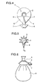
- FIG. 4 Another binding clip of this type is disclosed in Japanese Patent No. 2684937 proposed by the Applicant.
- This binding clip which is formed from a flat and thin plate made of resin as shown in Fig. 4, has an opening 2 extending from one end toward the center of the binding clip and a receiving portion 3 for receiving an object to be bound such as a bag, a net or the like in a central part of the binding clip in the depths of the opening 2.
- a pair of leg portions 4, 5 are formed on both sides of the opening, and hooklike engaging portions 6, 7 are formed at distal ends of the leg portions respectively.
- the object 9 is received in the receiving portion 3.
- the receiving portion 3 for receiving the object is reduced in diameter by crossing both the leg portions 4, 5 with each other to put the binding clip into a conical shape with the receiving portion 3 as an apex, thereby to exert a holding force on the object 9 to be bound in a direction of compressing the object.
- the engaging portions 6, 7 which are formed at the distal ends of the leg portions are engaged with each other to compress the object 9 to be bound as its diameter is reduced, thus completing the binding operation as shown in Fig. 6.
- the binding clip according to the invention is so constructed that a pair of engaging projections are formed at portions continuing from the opening to the receiving portion for receiving the object to be bound, the engaging projections being adapted to overlap each other and project into the receiving portion when the leg portions are crossed. Therefore, when the bag, net or the like is bound, a force of the object coming out toward the crossed parts of the leg portions will be divided in the two directions by means of the engaging projections, thus preventing the object to be bound from coming out toward the crossed parts of the leg portions.
- the engaging projections are pressed against the plastic bag, net or the like which tends to expand, and distal ends of the engaging projections hold the plastic bag, net or the like in a biting attitude, whereby a strong binding force can be obtained.
- the receiving portion for receiving the object to be bound is in a substantially triangular shape making a deepest end of the opening as an apex
- tapered portions consisting of the two edges having the deepest end as the apex act to press the plastic bag, net or the like, which tries to expand, toward the engaging projections, whereby a strong binding force can be obtained.
- the binding clip according to the invention is formed from a flat and thin plate made of resin, and includes an opening 10 tapered from one end of the binding clip toward its center in a V-shape, and a receiving portion 11 for receiving the object to be bound in a substantially triangular shape which is provided in a central part of the binding clip in the depths of the opening 10 communicating therewith and adapted to receive a bag, a net or the like.
- the receiving portion 11 is defined by receiving edges 20a, 20b which extend at an angle of substantially 90 degrees from an apex 23 in the deepest end.
- a pair of holding edges 19a, 19b are formed continuing from the receiving edges 20a, 20b, in a direction of right angle with respect to a longitudinal direction of the binding clip.
- Both the receiving edges 20a, 20b and the holding edges 19a, 19b are formed in a crooked shape in cooperation with their respective mating edges.
- a pair of leg portions 12a, 12b are formed on both sides of the opening 10, and hooklike engaging portions 14a, 14b are formed at distal ends of both the leg portions.
- the opening 10 has opening edges 10a, 10b, and a pair of engaging projections 18a, 18b are formed at connecting portions 16a, 16b between the opening edges 10a, 10b and holding edges 19a, 19b respectively.
- the object 9 to be bound is inserted from the opening 10 of the binding clip 1' toward the receiving portion 11. Since the opening 10 is provided with the opening edges 10a, 10b tapered toward the center, the object 9 to be bound can be smoothly inserted. As the object 9 to be bound is inserted further, it will be received in the receiving portion 11 after the engaging projections 18a, 18b are elastically deformed to pass it through.
- both the leg portions 12a, 12b are crossed with each other as shown in Fig. 2.
- the binding clip is deformed into a conical shape which is enlarged downward with the receiving portion 11, corresponding to the receiving portion 3 in Fig. 6, as an apex so as to bind the object 9.
- the engaging portions 14a, 14b, corresponding to the engaging portions 6, 7 in Fig. 6, may be hooked with each other as shown in Figs. 2 and 4, or mechanical means, for example, bonding of the crossed parts of both the leg portions by heat welding or so, caulking them with a press or the like, or stapling means such as a stapler or the like can be employed.
- a shape of the receiving portion 11 when the leg portions 12a, 12b are crossed with each other will be in a state where the engaging projections 18a, 18b are overlapped on each other and projected into the receiving portion 11 in a crooked shape, making the overlapped parts of the engaging projections as an apex as shown in Fig. 2, and an acute angle will be formed between the receiving edges 20a and 20b with the apex 23 as a starting point, thus reducing an area of the receiving portion 11.
- the object 9 will be clamped by the receiving edges 20a, 20b and guided by the receiving edges 20a, 20b to be pushed out toward the opening 10.
- the object 9 will receive a force divided in two directions of b and b', so as to be pushed out in the two directions into relief portions 21a, 21b while bulging, and then, bound.
- energy of the compressed object 9 will be divided in two as described above, and at the same time, will not expand the binding clip, because the object 9 is pressed by the holding edges 19a, 19b.
- the binding clip 1' according to the invention has been described in detail referring to the embodiment in which it is used in a form of a single binding clip.
- a number of the binding clips connected with one another can be used by connecting the distal portions of both the leg portions of a binding clip with both shoulder portions formed at upper ends of both the leg portions of another binding clip at connecting parts 24a, 24b as shown in Fig. 7.
- a number of the binding clips thus connected with one another can be wound into a roll shape to form an assembly consisting of 500 to 2000 clips, and the assembly of the clips can be loaded in a binding machine, which is not shown, to conduct a binding operation, whereby a rapid binding operation can be continuously conducted.
- the binding clip according to the invention is so constructed that a pair of engaging projections are formed at portions continuing from the opening to the receiving portion for receiving the object to be bound, the engaging projections being adapted to overlap each other and project into the receiving portion for receiving the object to be bound when the leg portions are crossed. Therefore, when the bag, net or the like is bound, a force of the object coming out toward the crossed parts of the leg portions will be divided in the two directions by means of the engaging projections, thus preventing the object to be bound from coming out toward the crossed parts of the leg portions.
- the engaging projections are pressed against the plastic bag, net or the like which tends to expand, and the distal ends of the engaging projections hold the plastic bag, net or the like in a biting attitude, whereby the strong binding force can be obtained.
- the receiving portion for receiving the object to be bound is in a substantially triangular shape making the deepest end of the opening as the apex, the tapered portions consisting of the two edges with the deepest end as the apex act to press the plastic bag, net or the like toward the engaging projections, whereby the strong binding force can be obtained.
Landscapes
- Engineering & Computer Science (AREA)
- Mechanical Engineering (AREA)
- Auxiliary Apparatuses For Manual Packaging Operations (AREA)
- Bag Frames (AREA)
- Package Closures (AREA)
- Clamps And Clips (AREA)
- Insertion Pins And Rivets (AREA)
Description
- The present invention relates to a binding clip according to the preamble part of
claim 1. - A binding clip with the features in the preamble of
claim 1 is disclosed in document US-A-4 896 366 where the receiving portion has an arrow shape. - Another binding clip of this type is disclosed in Japanese Patent No. 2684937 proposed by the Applicant. This binding clip which is formed from a flat and thin plate made of resin as shown in Fig. 4, has an
opening 2 extending from one end toward the center of the binding clip and a receivingportion 3 for receiving an object to be bound such as a bag, a net or the like in a central part of the binding clip in the depths of theopening 2. A pair ofleg portions engaging portions - In order to bind the
object 9 to be bound with this binding clip, theobject 9 is received in thereceiving portion 3. Then, thereceiving portion 3 for receiving the object is reduced in diameter by crossing both theleg portions receiving portion 3 as an apex, thereby to exert a holding force on theobject 9 to be bound in a direction of compressing the object. In this state, theengaging portions object 9 to be bound as its diameter is reduced, thus completing the binding operation as shown in Fig. 6. - However, in case where an elastic material such as a plastic bag, a net or the like is to be bound with the above described binding clip, after the
object 9 has been bound, a restitutive force is exerted in an outward direction of the bound portion as shown in Fig. 5. The force is converged on thecrossed parts 8 of theleg portions receiving portion 3 in a direction of A. Therefore, it has been a problem that the holding force will be lowered. Moreover, it has been another problem that commercial value will be degraded due to a bad appearance of the product because theobject 9 to be bound has come out. - It is an object of the invention to improve a known binding clip for reliably holding and binding an object to be bound even in case where an elastic material such as a bag, a net or the like is to be bound.
- This object will be achieved with a know binding clip comprising the features of the characterizing part of
claim 1. - As described, the binding clip according to the invention is so constructed that a pair of engaging projections are formed at portions continuing from the opening to the receiving portion for receiving the object to be bound, the engaging projections being adapted to overlap each other and project into the receiving portion when the leg portions are crossed. Therefore, when the bag, net or the like is bound, a force of the object coming out toward the crossed parts of the leg portions will be divided in the two directions by means of the engaging projections, thus preventing the object to be bound from coming out toward the crossed parts of the leg portions.
- Further, because a force of the plastic bag, net or the like which tends to expand will be held by the receiving portion and the engaging projections, the engaging projections are pressed against the plastic bag, net or the like which tends to expand, and distal ends of the engaging projections hold the plastic bag, net or the like in a biting attitude, whereby a strong binding force can be obtained.
- Still further, because the receiving portion for receiving the object to be bound is in a substantially triangular shape making a deepest end of the opening as an apex, tapered portions consisting of the two edges having the deepest end as the apex act to press the plastic bag, net or the like, which tries to expand, toward the engaging projections, whereby a strong binding force can be obtained.
-
- Fig. 1 is a plan view of a binding clip according to the invention.
- Fig. 2 is a plan view showing a state where leg portions of the binding clip according to the invention are crossed with each other.
- Fig. 3 is an enlarged view of a receiving portion for receiving an object to be bound in Fig. 2.
- Fig. 4 is a plan view showing a state where leg portions of a conventional binding clip are crossed with each other.
- Fig. 5 is an enlarged view of a receiving portion for receiving an object to be bound in the conventional binding clip.
- Fig. 6 is a side view showing a state where the object to be bound has been bound by the binding clip.
- Fig. 7 is a plan view showing the binding clips in a connected state.
-
- Now, an embodiment of the invention will be described. As shown in Fig. 1, the binding clip according to the invention is formed from a flat and thin plate made of resin, and includes an
opening 10 tapered from one end of the binding clip toward its center in a V-shape, and a receivingportion 11 for receiving the object to be bound in a substantially triangular shape which is provided in a central part of the binding clip in the depths of the opening 10 communicating therewith and adapted to receive a bag, a net or the like. - The
receiving portion 11 is defined byreceiving edges apex 23 in the deepest end. A pair ofholding edges receiving edges receiving edges holding edges - A pair of
leg portions engaging portions - The
opening 10 hasopening edges engaging projections portions opening edges holding edges - Now, operation of the binding clip of the above described structure will be explained.
- First, the
object 9 to be bound is inserted from theopening 10 of the binding clip 1' toward thereceiving portion 11. Since theopening 10 is provided with theopening edges object 9 to be bound can be smoothly inserted. As theobject 9 to be bound is inserted further, it will be received in the receivingportion 11 after theengaging projections - After the
object 9 to be bound has been received in thereceiving portion 11, theholding edges object 9 to be bound in thereceiving portion 11. In this state, both theleg portions receiving portion 11, corresponding to thereceiving portion 3 in Fig. 6, as an apex so as to bind theobject 9. As means for maintaining this state, theengaging portions engaging portions - A shape of the
receiving portion 11 when theleg portions engaging projections receiving portion 11 in a crooked shape, making the overlapped parts of the engaging projections as an apex as shown in Fig. 2, and an acute angle will be formed between thereceiving edges apex 23 as a starting point, thus reducing an area of thereceiving portion 11. - In this state, the
object 9 will be clamped by thereceiving edges receiving edges opening 10. However, due to the presence of theholding edges engaging projections object 9 will receive a force divided in two directions of b and b', so as to be pushed out in the two directions intorelief portions compressed object 9 will be divided in two as described above, and at the same time, will not expand the binding clip, because theobject 9 is pressed by theholding edges - Moreover, because the
engaging projections compressed object 9, the binding force will be further enhanced. - The binding clip 1' according to the invention has been described in detail referring to the embodiment in which it is used in a form of a single binding clip. However, a number of the binding clips connected with one another can be used by connecting the distal portions of both the leg portions of a binding clip with both shoulder portions formed at upper ends of both the leg portions of another binding clip at connecting
parts - A number of the binding clips thus connected with one another can be wound into a roll shape to form an assembly consisting of 500 to 2000 clips, and the assembly of the clips can be loaded in a binding machine, which is not shown, to conduct a binding operation, whereby a rapid binding operation can be continuously conducted.
- As described hereinabove, the binding clip according to the invention is so constructed that a pair of engaging projections are formed at portions continuing from the opening to the receiving portion for receiving the object to be bound, the engaging projections being adapted to overlap each other and project into the receiving portion for receiving the object to be bound when the leg portions are crossed. Therefore, when the bag, net or the like is bound, a force of the object coming out toward the crossed parts of the leg portions will be divided in the two directions by means of the engaging projections, thus preventing the object to be bound from coming out toward the crossed parts of the leg portions.
- Further, because the force of the plastic bag, net or the like which tends to expand will be held by the receiving portion and the engaging projections, the engaging projections are pressed against the plastic bag, net or the like which tends to expand, and the distal ends of the engaging projections hold the plastic bag, net or the like in a biting attitude, whereby the strong binding force can be obtained.
- Still further, because the receiving portion for receiving the object to be bound is in a substantially triangular shape making the deepest end of the opening as the apex, the tapered portions consisting of the two edges with the deepest end as the apex act to press the plastic bag, net or the like toward the engaging projections, whereby the strong binding force can be obtained.
Claims (9)
- A binding clip (1) formed from a flat plate material, the binding clip (1) comprising:an opening (10) at one end;a receiving portion (11) for receiving an object (9) to be bound in a depth of the opening (10);a pair of leg portions (12a, 12b) defining the opening (10) and adapted to be crossed with each other to bind the object (9); anda pair of engaging projections (18a, 18b) bulging at portions continuing from the opening (10) to the receiving portion (11), characterized in that said receiving portion (11) is further defined by receiving edges (20a, 20b) extending at an angle of substantially 90 degrees from an apex in a deepest end of said receiving portion (11), and a pair of holding edges (19a, 19b) being formed continuing from the receiving edges (20a, 20b) in a direction of right angle with respect to a longitudinal direction of the binding clip (1).
- The binding clip (1) according to claim 1, wherein said engaging projections (18a, 18b) are arranged to bite the bound object (9) when said leg portions (12a, 12b) are crossed.
- The binding clip (1) according to claim 1, wherein said opening (10) includes opening edges (10a, 10b) tapered toward said receiving portion (11).
- The binding clip (1) according to claim 1, wherein said leg portions (12a, 12b) include engaging portions (14a, 14b) and are hooked with each other when said leg portions (12a, 12b) are crossed.
- The binding clip (1) according to claim 1, wherein said leg portions (12a, 12b) are held by at least one of bonding, caulking and stapling when said leg portions (12a, 12b) are crossed.
- A clip assembly, wherein a plurality of binding clips (1) according to one of claims 1-5 are connected at distal portions of said binding clip (1).
- The binding clip (1) according to claim 1, wherein said engaging projections (18a, 18b) bulge toward one another when said leg portions (12a, 12b) are uncrossed;
wherein said engaging projections (18a, 18b) are adapted to overlap each other and project into said receiving portion (11) when said leg portions (12a, 12b) are crossed; and
wherein said engaging projections (18a, 18b) divide in two directions an expending force of the bound object (9) tending to uncross the leg portions (12a, 12b) when said engaging projections (18a, 18b) are overlapped so as not to expand the binding clip (1). - The binding clip (1) according to claim 1, wherein the receiving portion (11) is formed by walls that define a triangle when the leg portions (12a, 12b) are not crossed and includes one wall of the triangle extending into the receiving portion (11) when the leg portions (12a, 12b) are crossed.
- The binding clip (1) according to claim 1, wherein the receiving portion (11) is formed by walls, each wall defining an imaginary line that extends outside of the receiving portion (11) when the leg portions (12a, 12b) are not crossed, and wherein at least one imaginary line extends into the receiving portion (11) when the leg portions (12a, 12b) are crossed, wherein the receiving portion (11) is shaped like a triangle.
Applications Claiming Priority (2)
| Application Number | Priority Date | Filing Date | Title |
|---|---|---|---|
| JP19956399 | 1999-07-13 | ||
| JP19956399A JP3674395B2 (en) | 1999-07-13 | 1999-07-13 | Binding clip |
Publications (3)
| Publication Number | Publication Date |
|---|---|
| EP1069050A2 EP1069050A2 (en) | 2001-01-17 |
| EP1069050A3 EP1069050A3 (en) | 2001-12-19 |
| EP1069050B1 true EP1069050B1 (en) | 2004-09-29 |
Family
ID=16409920
Family Applications (1)
| Application Number | Title | Priority Date | Filing Date |
|---|---|---|---|
| EP00115218A Expired - Lifetime EP1069050B1 (en) | 1999-07-13 | 2000-07-13 | Binding clip |
Country Status (4)
| Country | Link |
|---|---|
| US (1) | US6591460B1 (en) |
| EP (1) | EP1069050B1 (en) |
| JP (1) | JP3674395B2 (en) |
| DE (1) | DE60014260T2 (en) |
Families Citing this family (12)
| Publication number | Priority date | Publication date | Assignee | Title |
|---|---|---|---|---|
| NL1024491C2 (en) * | 2003-10-09 | 2005-04-12 | Schutte Holding B V | Method for closing a flexible package, a device therefor and a closed flexible package. |
| US7565780B2 (en) * | 2005-02-04 | 2009-07-28 | Poly-Clip System Corp. | Clip and clipper |
| BRPI0707265A2 (en) * | 2006-01-27 | 2011-04-26 | Poly Clip System Corp | stapler and stapler |
| KR200447166Y1 (en) * | 2009-06-15 | 2009-12-29 | 김성현 | Clip |
| US9403630B2 (en) * | 2010-08-05 | 2016-08-02 | The Lindy Bowman Company | System, method and apparatus for gift bag binding |
| US8931242B1 (en) * | 2012-06-05 | 2015-01-13 | Louis Sardo | Stretchable gift wrap system |
| USD707553S1 (en) * | 2013-03-08 | 2014-06-24 | Joshua Vantrease | Enclosure fastener |
| USD880296S1 (en) | 2018-09-25 | 2020-04-07 | Klr Systems Inc. | Bag closure clip |
| USD871212S1 (en) | 2018-09-25 | 2019-12-31 | Klr Systems Inc. | Bag closure clip |
| USD1005104S1 (en) * | 2019-09-27 | 2023-11-21 | Bedford Industries, Inc. | Closure roll |
| US20220297891A1 (en) * | 2021-03-16 | 2022-09-22 | Frank Matte | Bag fastener for flexible bags |
| USD1028649S1 (en) * | 2023-05-10 | 2024-05-28 | Jikke Roos Amalia de Jong | Plant-clip |
Family Cites Families (22)
| Publication number | Priority date | Publication date | Assignee | Title |
|---|---|---|---|---|
| US3234616A (en) * | 1965-02-16 | 1966-02-15 | Edward F Wantland | Ring fasteners |
| US3535746A (en) * | 1966-11-07 | 1970-10-27 | Stanley E Thomas Jr | Reusable bag fastener |
| GB1446012A (en) | 1973-07-05 | 1976-08-11 | Britt J P | Packaging |
| US3882573A (en) * | 1974-01-02 | 1975-05-13 | Jr Stanley E Thomas | Flexible, reusable fastener |
| US3910811A (en) | 1974-07-18 | 1975-10-07 | Kwik Lok | Method and machine for removeably securing stiff plastic closures flat against series of moving packages |
| US4174554A (en) * | 1978-07-14 | 1979-11-20 | Bonar & Bemis Ltd. | Bag closure |
| US4357186A (en) | 1980-06-17 | 1982-11-02 | The Mead Corporation | Machine and method for forming and applying carrying straps to article cartons |
| JPS57125106A (en) | 1981-01-28 | 1982-08-04 | Toshiyuki Kokito | Packer for food |
| US4497091A (en) * | 1983-03-18 | 1985-02-05 | Elliott Jon S | Twist clip |
| US4896366A (en) | 1988-11-18 | 1990-01-23 | World Manufacturing, Inc. | T-shirt bag closure |
| US5269120A (en) | 1990-09-17 | 1993-12-14 | Kwik Lok Corporation | System for marking and installing closures |
| US5425826A (en) | 1991-06-28 | 1995-06-20 | The Boeing Company | Method and apparatus for forming a welded identification sleeve |
| JP2684937B2 (en) * | 1992-09-07 | 1997-12-03 | マックス株式会社 | Binding method and binding tool |
| US5286110A (en) * | 1993-04-01 | 1994-02-15 | Mickey Benson | Bag having tamper-resistant seal |
| US5485711A (en) * | 1993-08-20 | 1996-01-23 | Max Co., Ltd. | Binding machine |
| US5564255A (en) | 1994-09-28 | 1996-10-15 | Tetra Laval Holdings & Finance S.A. | Apparatus and method for sealing and creasing gabled containers |
| JP3355469B2 (en) * | 1996-04-30 | 2002-12-09 | 保男 樋口 | Bag tie for packaging |
| US5782067A (en) | 1996-06-28 | 1998-07-21 | Free-Flow Packaging International, Inc. | Bag sealer and cutter for use in packaging loose fill packaging materials |
| JP3491462B2 (en) | 1996-08-13 | 2004-01-26 | マックス株式会社 | Unity method |
| JP3147006B2 (en) | 1996-10-08 | 2001-03-19 | マックス株式会社 | Bag binding machine and binding method for binding bags |
| DE69908196T2 (en) | 1998-02-16 | 2003-11-27 | Max Co. Ltd., Tokio/Tokyo | binding machine |
| US6112499A (en) | 1999-01-19 | 2000-09-05 | Hellermanntyton Corporation | Bag closure apparatus |
-
1999
- 1999-07-13 JP JP19956399A patent/JP3674395B2/en not_active Expired - Fee Related
-
2000
- 2000-07-12 US US09/614,703 patent/US6591460B1/en not_active Expired - Fee Related
- 2000-07-13 EP EP00115218A patent/EP1069050B1/en not_active Expired - Lifetime
- 2000-07-13 DE DE60014260T patent/DE60014260T2/en not_active Expired - Fee Related
Also Published As
| Publication number | Publication date |
|---|---|
| EP1069050A2 (en) | 2001-01-17 |
| US6591460B1 (en) | 2003-07-15 |
| JP3674395B2 (en) | 2005-07-20 |
| EP1069050A3 (en) | 2001-12-19 |
| DE60014260T2 (en) | 2005-02-03 |
| DE60014260D1 (en) | 2004-11-04 |
| JP2001031029A (en) | 2001-02-06 |
Similar Documents
| Publication | Publication Date | Title |
|---|---|---|
| EP1069050B1 (en) | Binding clip | |
| US3722670A (en) | Clip stack | |
| US5314065A (en) | Sheet metal clip | |
| JPH02292506A (en) | Device for connecting two edges of flat member | |
| US5303821A (en) | Resilient clip assembly | |
| US7937813B2 (en) | Clip | |
| CA2200791C (en) | Improved puzzle-lock compression ring | |
| US5117536A (en) | Binding strap with integral connecting structure and anti-disengagement feature | |
| US5927491A (en) | Resilient U-clip assembly | |
| US5682994A (en) | Collated clip assembly | |
| US2033613A (en) | Staple | |
| US5314064A (en) | Sheet metal clip | |
| US8122571B2 (en) | Closure clip and process for the production thereof | |
| US5878880A (en) | Collated clip assembly | |
| US4151634A (en) | Plate connector for conveyor belts and method for securing such plate connector to conveyor belts | |
| JPH0563366B2 (en) | ||
| JP4532770B2 (en) | Connecting bracket | |
| JP3685323B2 (en) | Pressure contact terminal fitting and manufacturing method thereof | |
| US5068945A (en) | Fastener | |
| EP1493683A1 (en) | Closure, and method and apparatus for attachment of a closure | |
| JPH10316131A (en) | Partition panel and partition body for packaging box | |
| JP3005271U (en) | Staple with a pullout prevention function | |
| JPS61244746A (en) | Cleavable can member | |
| WO1997033816A1 (en) | Improved resilient u-clip assembly | |
| AU729721B2 (en) | Improved puzzle-lock compression ring |
Legal Events
| Date | Code | Title | Description |
|---|---|---|---|
| PUAI | Public reference made under article 153(3) epc to a published international application that has entered the european phase |
Free format text: ORIGINAL CODE: 0009012 |
|
| AK | Designated contracting states |
Kind code of ref document: A2 Designated state(s): AT BE CH CY DE DK ES FI FR GB GR IE IT LI LU MC NL PT SE Kind code of ref document: A2 Designated state(s): DE FR GB |
|
| AX | Request for extension of the european patent |
Free format text: AL;LT;LV;MK;RO;SI |
|
| PUAL | Search report despatched |
Free format text: ORIGINAL CODE: 0009013 |
|
| AK | Designated contracting states |
Kind code of ref document: A3 Designated state(s): AT BE CH CY DE DK ES FI FR GB GR IE IT LI LU MC NL PT SE |
|
| AX | Request for extension of the european patent |
Free format text: AL;LT;LV;MK;RO;SI |
|
| 17P | Request for examination filed |
Effective date: 20020606 |
|
| AKX | Designation fees paid |
Free format text: DE FR GB |
|
| 17Q | First examination report despatched |
Effective date: 20021001 |
|
| GRAP | Despatch of communication of intention to grant a patent |
Free format text: ORIGINAL CODE: EPIDOSNIGR1 |
|
| GRAS | Grant fee paid |
Free format text: ORIGINAL CODE: EPIDOSNIGR3 |
|
| GRAA | (expected) grant |
Free format text: ORIGINAL CODE: 0009210 |
|
| AK | Designated contracting states |
Kind code of ref document: B1 Designated state(s): DE FR GB |
|
| REG | Reference to a national code |
Ref country code: GB Ref legal event code: FG4D |
|
| REG | Reference to a national code |
Ref country code: IE Ref legal event code: FG4D |
|
| REF | Corresponds to: |
Ref document number: 60014260 Country of ref document: DE Date of ref document: 20041104 Kind code of ref document: P |
|
| ET | Fr: translation filed | ||
| PLBE | No opposition filed within time limit |
Free format text: ORIGINAL CODE: 0009261 |
|
| STAA | Information on the status of an ep patent application or granted ep patent |
Free format text: STATUS: NO OPPOSITION FILED WITHIN TIME LIMIT |
|
| 26N | No opposition filed |
Effective date: 20050630 |
|
| PGFP | Annual fee paid to national office [announced via postgrant information from national office to epo] |
Ref country code: FR Payment date: 20090710 Year of fee payment: 10 |
|
| PGFP | Annual fee paid to national office [announced via postgrant information from national office to epo] |
Ref country code: DE Payment date: 20090709 Year of fee payment: 10 Ref country code: GB Payment date: 20090708 Year of fee payment: 10 |
|
| GBPC | Gb: european patent ceased through non-payment of renewal fee |
Effective date: 20100713 |
|
| REG | Reference to a national code |
Ref country code: FR Ref legal event code: ST Effective date: 20110331 |
|
| PG25 | Lapsed in a contracting state [announced via postgrant information from national office to epo] |
Ref country code: DE Free format text: LAPSE BECAUSE OF NON-PAYMENT OF DUE FEES Effective date: 20110201 |
|
| REG | Reference to a national code |
Ref country code: DE Ref legal event code: R119 Ref document number: 60014260 Country of ref document: DE Effective date: 20110201 |
|
| PG25 | Lapsed in a contracting state [announced via postgrant information from national office to epo] |
Ref country code: FR Free format text: LAPSE BECAUSE OF NON-PAYMENT OF DUE FEES Effective date: 20100802 |
|
| PG25 | Lapsed in a contracting state [announced via postgrant information from national office to epo] |
Ref country code: GB Free format text: LAPSE BECAUSE OF NON-PAYMENT OF DUE FEES Effective date: 20100713 |