EP1069045A1 - Vorrichtung zum Zuführen von Klebstoff zu Ausgabeköpfen - Google Patents
Vorrichtung zum Zuführen von Klebstoff zu Ausgabeköpfen Download PDFInfo
- Publication number
- EP1069045A1 EP1069045A1 EP00114261A EP00114261A EP1069045A1 EP 1069045 A1 EP1069045 A1 EP 1069045A1 EP 00114261 A EP00114261 A EP 00114261A EP 00114261 A EP00114261 A EP 00114261A EP 1069045 A1 EP1069045 A1 EP 1069045A1
- Authority
- EP
- European Patent Office
- Prior art keywords
- adhesive
- sliders
- heads
- joint
- fixed
- Prior art date
- Legal status (The legal status is an assumption and is not a legal conclusion. Google has not performed a legal analysis and makes no representation as to the accuracy of the status listed.)
- Withdrawn
Links
- 239000000853 adhesive Substances 0.000 title claims abstract description 32
- 230000001070 adhesive effect Effects 0.000 title claims abstract description 32
- 239000004831 Hot glue Substances 0.000 claims abstract description 10
- 238000007789 sealing Methods 0.000 claims description 10
- 239000002184 metal Substances 0.000 claims description 4
- 239000000523 sample Substances 0.000 claims description 3
- 238000005485 electric heating Methods 0.000 claims description 2
- 238000003466 welding Methods 0.000 claims description 2
- 230000006978 adaptation Effects 0.000 claims 1
- 239000000463 material Substances 0.000 claims 1
- 238000010276 construction Methods 0.000 description 3
- 238000010438 heat treatment Methods 0.000 description 2
- 238000012423 maintenance Methods 0.000 description 2
- 230000010355 oscillation Effects 0.000 description 2
- 230000003068 static effect Effects 0.000 description 2
- 238000000151 deposition Methods 0.000 description 1
- 239000012530 fluid Substances 0.000 description 1
- 230000002452 interceptive effect Effects 0.000 description 1
Images


Classifications
-
- B—PERFORMING OPERATIONS; TRANSPORTING
- B65—CONVEYING; PACKING; STORING; HANDLING THIN OR FILAMENTARY MATERIAL
- B65B—MACHINES, APPARATUS OR DEVICES FOR, OR METHODS OF, PACKAGING ARTICLES OR MATERIALS; UNPACKING
- B65B51/00—Devices for, or methods of, sealing or securing package folds or closures; Devices for gathering or twisting wrappers, or necks of bags
- B65B51/02—Applying adhesives or sealing liquids
- B65B51/023—Applying adhesives or sealing liquids using applicator nozzles
-
- B—PERFORMING OPERATIONS; TRANSPORTING
- B05—SPRAYING OR ATOMISING IN GENERAL; APPLYING FLUENT MATERIALS TO SURFACES, IN GENERAL
- B05B—SPRAYING APPARATUS; ATOMISING APPARATUS; NOZZLES
- B05B15/00—Details of spraying plant or spraying apparatus not otherwise provided for; Accessories
- B05B15/60—Arrangements for mounting, supporting or holding spraying apparatus
- B05B15/65—Mounting arrangements for fluid connection of the spraying apparatus or its outlets to flow conduits
-
- B—PERFORMING OPERATIONS; TRANSPORTING
- B05—SPRAYING OR ATOMISING IN GENERAL; APPLYING FLUENT MATERIALS TO SURFACES, IN GENERAL
- B05B—SPRAYING APPARATUS; ATOMISING APPARATUS; NOZZLES
- B05B15/00—Details of spraying plant or spraying apparatus not otherwise provided for; Accessories
- B05B15/60—Arrangements for mounting, supporting or holding spraying apparatus
- B05B15/68—Arrangements for adjusting the position of spray heads
-
- B—PERFORMING OPERATIONS; TRANSPORTING
- B31—MAKING ARTICLES OF PAPER, CARDBOARD OR MATERIAL WORKED IN A MANNER ANALOGOUS TO PAPER; WORKING PAPER, CARDBOARD OR MATERIAL WORKED IN A MANNER ANALOGOUS TO PAPER
- B31B—MAKING CONTAINERS OF PAPER, CARDBOARD OR MATERIAL WORKED IN A MANNER ANALOGOUS TO PAPER
- B31B50/00—Making rigid or semi-rigid containers, e.g. boxes or cartons
- B31B50/60—Uniting opposed surfaces or edges; Taping
- B31B50/62—Uniting opposed surfaces or edges; Taping by adhesives
- B31B50/622—Applying glue on already formed boxes
Definitions
- the adhesive is supplied by heads operated by a pneumatic drive and connected to the ends of corresponding high-pressure ducts which are electrically heated and thermostatically controlled and whose other ends are connected to a reservoir which contains the melted adhesive at high pressure.
- heads operated by a pneumatic drive and connected to the ends of corresponding high-pressure ducts which are electrically heated and thermostatically controlled and whose other ends are connected to a reservoir which contains the melted adhesive at high pressure.
- Each block is provided with a pair of transverse holes, connected at the front to the channels used for transporting the adhesive and to the channels used for transporting the compressed air for opening and closing the nozzle of each head, and connected at the rear to corresponding slots parallel to the longitudinal axis of the blocks; into these holes there open pairs of holes formed in the guide unit where the adhesive holes are interconnected in a branching way and are connected to a common heated duct for the supply of the adhesive under pressure, while the holes of the actuators are connected to a common source of supply of pressurized fluid through an electrically-operated shut-off valve or through corresponding electrically-operated shut-off valves.
- the invention is designed to overcome these and other problems with the following idea for a solution.
- the adhesive-dispensing heads are fixed on corresponding sliders which are heated and mounted, with the possibility of adjusting the distance between them, on a straight guide fixed to the movement and support means of the apparatus on which are mounted the electrically-operated pneumatic valves which cause the opening and closing of the heads.
- the ducts which supply the adhesive to the heads are connected to channels formed in the sliders and these channels are connected directly or through secondary rotary joints which form cylindrical articulations with two heated arms which are longitudinally hollow, and whose other ends are connected directly or through further secondary rotary joints to a primary rotary joint to which the flexible, heated and thermostatically controlled hot-melt adhesive supply duct is connected.
- the apparatus is mounted on a reciprocating movement system, for example one of the type described in Italian patent no. 1,273,244 filed on 3 February 1994 in the name of SENZANI BREVETTI OFFICINE DI FAENZA S.R.L.
- the primary rotary joint is of the front seal type and the adhesive supply duct is orientated in such a way that it is subjected to less intense oscillations, which protect it from fracture.
- the following description relates to an apparatus for dispensing streams of adhesive orientated downwards, to be applied to the top of a box which is to be closed and which is arranged vertically, so that the terms "high”, “low”, “above” and “under” relate to this use of the apparatus.
- the apparatus can be used in an inverted configuration to distribute streams of adhesive on the lower part of a box to close it at the bottom and to prepare it for filling.
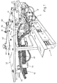
- the apparatus comprises a straight guide 1 fixed in its mid-point under a support 10 and provided with longitudinal slots 2-2' penetrated by pairs of screws 3-3' by which sliders 4-4' are fixed under the guide, with the possibility of adjustment of their distance from each other, these sliders, as shown in the example in Figure 5, having an L-shaped profile and carrying the frontally fixed adhesive-dispensing heads 5, 5' which are positioned vertically and orientated with their nozzles pointing downwards.
- Each head is connected to the control circuit of the moving element for opening and closing the nozzle, at the end of a corresponding channel 6 which is formed in each of the said sliders 4, 4' (Fig.
- each slider indicates a seat which is formed in each slider and which can house a resistor which keeps the slider at a predetermined temperature, controlled by means of a thermostatic probe located in the seat 9.
- Each head 5 is connected to the circuit for the passage of the adhesive at the end of a corresponding channel 11 opening into a vertical hole 12, closed at the bottom, which is provided in each projecting part 104, 104' of the sliders 4, 4', these parts being pivoted, for example, by means of secondary rotary joints D2, D2' with vertical axes (Fig.
- the joint D1 is provided with an annular recess 26 having at least one side flattened in the form of a secant 126 which interacts with a horizontal fork 27 in such a way that it can slide longitudinally in the latter but cannot rotate, this fork being integral with the mid-point of the guide 1, perpendicular to it, and consequently fixed to the support 10.
- the secondary rotary joints D2, D2' are of a simplified type, with lateral seals, since their components rotate with respect to each other only during the adjustment of the distance between the heads 5, 5', regardless of whether the apparatus is used in a static or dynamic way.
- the blind holes 12 of the projecting part 104, 104' of each slider are provided with intermediate threaded portions 112 and are provided with enlarged upper portions 212 in which are housed sealing gaskets 13 which surround the upper parts of the threaded terminal portions of corresponding screws 14 which are screwed and locked into the said holes 12 and which pass through end holes 15 of the arms 16, 16', allowing these arms to oscillate with respect to the sliders.
- the holes 15 are provided with intermediate annular recesses 19 into which the longitudinal channels 17, 17' of the arms 16, 16' open, and which are also penetrated by intermediate portions of the said screws 14, 14', provided with T-shaped holes 20 and 21, which connected the said recesses 19 to the channels 11 of the sliders 4, 4'.
- the channel 11 which supplies the adhesive to the dispensing heads 5, 5' is thus connected to the longitudinal channels of the arms 16, 16' which can oscillate about the axis of the screws 14.
- Annular sealing gaskets 22 and 23, mounted for example in corresponding annular recesses of the screws 14, are provided above and below the annular recess 19.
- each arm 16, 16' is provided with a corresponding longitudinal seat 24 which houses an electrical heating resistor which is switched on and off as a shunt for the resistors for heating the aforesaid sliders and the principal joint D1 (see below).
- the primary rotary joint D1 can be of the same type as the aforesaid secondary joints D2, D2'.
- the primary joint D1 is preferably of the type with frontal seals, as described above with reference to Figures 2, 3, 4 and 6.
- the longitudinal channels 17, 17' of the arms 16, 16' open into corresponding end holes 18, 18' penetrated by the cylindrical shank 125 of a mushroom-shaped body 25 whose head 225 is provided with the aforesaid annular recess 26 which interacts with the guide fork 27 used for the self-centring adjustment of the distance between the sliders 5, 5'.
- a washer 70 and an elastic ring 71 axially retain the arms 16, 16' on the shank 125 of the mushroom-shaped body 25, which is provided at different heights with radial holes 28, 29 which are connected to annular recesses 30, 31 of the said holes 18, 18' of the arms 16, 16', with the provision of sealing gaskets 73, 74, located for example in corresponding annular recesses of the shank 125 of the mushroom-shaped body, above and below the said recesses.
- the said holes 28, 29 communicate with an axial hole 32 of the shank 125 of the mushroom-shaped body, which opens in the head of the mushroom-shaped body in two portions whose diameter increases in the upward direction, and in the first of which is mounted the head of a cylinder 33 which engages the said hole 32 with a lateral seal provided by an annular gasket 34, is pushed upward by a spring 35 with suitable characteristics positioned, for example, on the bottom of the said hole 32, and is prevented from rotating, for example by a pin 72 which leaves the cylinder free to move axially.
- the cylinder 33 is pierced axially as indicated by 37 and carries at its top an axial seat in which an annular insert 36 of hard metal, for example Widia, is fixed so that it partially projects.
- This insert is welded with a lateral seal into the seat of the cylinder, for example by braze welding, and is then ground on the frontal surface which can interact with an annual insert 38 having the same characteristics, which is welded with an exact degree of projection and with a lateral seal in an axial seat provided on the head of an inverted mushroom-shaped body 39 mounted rotatably in the upper seat of the mushroom-shaped body 25 by means of a bearing 40 locked in place by means of the flange 225' which is fixed by screws 41 and which forms part of the head 225 of the said mushroom-shaped body 25.
- the insert 38 and the mushroom-shaped body 39 are penetrated axially by a hole 42 which is closed at the top and to which are connected radial holes 43 which open into an annular recess 53 of the shank of the mushroom-shaped body 39 on which a body 45, fixed axially by means of the screw 46, is mounted with the interposition of sealing gaskets 44.
- the body 45 is provided with seats 47 and 48 for housing an electric heating resistor and a thermostatic probe.
- An arm 49 provided at its top with a longitudinal extension 50 slidable in a guide 51 supported with the possibility of rotation about a vertical axis by a fixed plate 52, is fixed to the body 45.
- the terminal portion of the flexible heated and thermostatically controlled duct 55 which supplies the hot-melt adhesive and which is connected to a radial hole 56 of the body 45 communicating with the aforesaid annular recess 53, is fixed by suitable means 54 to the said arm 49.
- the apparatus is used in a dynamic way and, for example, in the context of the system described in Italian patent no. 1,273,244 filed on 3 February 1994 in the name of SENZANI BREVETTI OFFICINE DI FAENZA S.R.L., the support 10 is fixed under the slider 57 which slides on a pair of horizontal straight guides 58 fixed under the plate 52 and orientated obliquely with respect to the straight arm of the transfer unit T along which the boxes A to be glued advance in single file.
- the number 59 indicates the connecting rod one end of which is pivoted at 60 on the slider 57 while its other end is pivoted at 61 on a crank 62 keyed to a vertical shaft 63 which is driven with an oscillating motion, in phase with the advance of the boxes A and at a speed such that the pair of adhesive-dispensing heads 5, 5' are made to undergo, cyclically, an oblique movement above or under the box to be closed, at a speed such that they follow the box in its advance in the direction indicated by the arrow F and also such that they move transversely with respect to the box to distribute two strips of adhesive S1, S1' on the box as shown in Figure 11.
- S2 indicates a further strip of adhesive distributed longitudinally on the moving box by a fixed dispensing head which is not illustrated in the drawings since it is not relevant to the understanding of the invention.
- the vertical axis 63 (Fig. 2) can form part of an oscillator, as specified in the patent cited above, or can form part of a movement system with an electric motor having electronically controlled speed and phase, for example with a brushless motor.
- the primary joint D1 can be provided with a part consisting of the shank of the body 25 and lateral extensions 64, 64' provided with vertical blind holes 65, 65' to which are connected inclined channels 66, 66' whose other ends communicate with the axial hole 32 which in this case is closed below by a cover 67 fixed with screws 68 and with a sealing gasket 69.
- the ends of the longitudinally hollow arms 16, 16' can be connected by secondary joints D3, D3', identical to the joints D2, D2' described above, to the aforesaid holes 65, 65', while their other ends are connected to the sliders 4, 4' in the way described or according to the aforesaid variant.
- Figure 7 shows how the inclined holes 66, 66' can be formed through the axial hole 32, with the cover 67 removed, without emerging from the extensions 64, 64'. By removing the cover 67 it is also possible to gain direct access to the spring 35 to replace it, if necessary, during the maintenance of the apparatus.
- the arms 16, 16' can be integral with, or formed in one piece with, the sliders 4, 4', which have an inverted L shape such that they are fixed by their upper parts to the slots of the straight guide 1 which is integral with the support 10 and is located in a position such that the theoretical vertical plane Q passing through the mid-line of the slots of this guide also contains the axis of the adhesive-dispensing heads 5, 5'.
Landscapes
- Engineering & Computer Science (AREA)
- Mechanical Engineering (AREA)
- Coating Apparatus (AREA)
- Replacement Of Web Rolls (AREA)
- Treatment Of Fiber Materials (AREA)
Applications Claiming Priority (2)
| Application Number | Priority Date | Filing Date | Title |
|---|---|---|---|
| ITBO990397 | 1999-07-16 | ||
| IT1999BO000397A IT1309337B1 (it) | 1999-07-16 | 1999-07-16 | Apparato per collegare in derivazione ad un unico condottod'alimentazione, una coppia di testine d'erogazione di colla, |
Publications (1)
| Publication Number | Publication Date |
|---|---|
| EP1069045A1 true EP1069045A1 (de) | 2001-01-17 |
Family
ID=11344126
Family Applications (1)
| Application Number | Title | Priority Date | Filing Date |
|---|---|---|---|
| EP00114261A Withdrawn EP1069045A1 (de) | 1999-07-16 | 2000-07-04 | Vorrichtung zum Zuführen von Klebstoff zu Ausgabeköpfen |
Country Status (2)
| Country | Link |
|---|---|
| EP (1) | EP1069045A1 (de) |
| IT (1) | IT1309337B1 (de) |
Cited By (4)
| Publication number | Priority date | Publication date | Assignee | Title |
|---|---|---|---|---|
| EP1240949A3 (de) * | 2000-12-04 | 2004-02-04 | Nordson Corporation | Vorrichtung zum Abgeben von Fluiden, insbesondere fliessfähigem Klebstoff |
| WO2005016556A1 (en) * | 2003-07-15 | 2005-02-24 | Kimberly-Clark Worldwide Inc. | Apparatus for depositing fluid material onto a substrate |
| CN104843238A (zh) * | 2015-04-03 | 2015-08-19 | 李志峰 | 一种蚕豆包装机粘合组件 |
| EP3024588B1 (de) * | 2013-07-23 | 2018-03-14 | Focke & Co. (GmbH & Co.) | Vorrichtung zum herstellen von packungen für zigaretten mit ventilanordnung |
Families Citing this family (1)
| Publication number | Priority date | Publication date | Assignee | Title |
|---|---|---|---|---|
| CN109018547A (zh) * | 2018-07-18 | 2018-12-18 | 广州市凯安消防科技有限公司 | 一种消防逃生头罩的滤毒罐自动化注胶设备 |
Citations (4)
| Publication number | Priority date | Publication date | Assignee | Title |
|---|---|---|---|---|
| EP0475224A2 (de) * | 1990-09-13 | 1992-03-18 | Nordson Corporation | Schnelljustiervorrichtung für mehrere Abgabevorrichtungen |
| EP0719591A2 (de) * | 1994-12-30 | 1996-07-03 | Nordson Corporation | Klebstoffspritzapparat mit einzeln einstellbaren Sprüheinheiten |
| ITBO950177U1 (it) | 1995-12-07 | 1997-06-07 | Senzani Brevetti Faenza Srl | Apparato per collegare in derivazione ad un unico condotto di alimentazion, una coppia di testine di erogazione di colla, |
| IT1273244B (it) | 1994-02-03 | 1997-07-07 | Senzani Brevetti Faenza Srl | Apparato per il fissaggio a tenuta delle alette di chiusura delle estremita' di astucci o scatole, mediante getti di colla erogati in parte sulle alette stesse con orientamento trasversale alla direzione d'avanzamento delle medesime scatole |
-
1999
- 1999-07-16 IT IT1999BO000397A patent/IT1309337B1/it active
-
2000
- 2000-07-04 EP EP00114261A patent/EP1069045A1/de not_active Withdrawn
Patent Citations (4)
| Publication number | Priority date | Publication date | Assignee | Title |
|---|---|---|---|---|
| EP0475224A2 (de) * | 1990-09-13 | 1992-03-18 | Nordson Corporation | Schnelljustiervorrichtung für mehrere Abgabevorrichtungen |
| IT1273244B (it) | 1994-02-03 | 1997-07-07 | Senzani Brevetti Faenza Srl | Apparato per il fissaggio a tenuta delle alette di chiusura delle estremita' di astucci o scatole, mediante getti di colla erogati in parte sulle alette stesse con orientamento trasversale alla direzione d'avanzamento delle medesime scatole |
| EP0719591A2 (de) * | 1994-12-30 | 1996-07-03 | Nordson Corporation | Klebstoffspritzapparat mit einzeln einstellbaren Sprüheinheiten |
| ITBO950177U1 (it) | 1995-12-07 | 1997-06-07 | Senzani Brevetti Faenza Srl | Apparato per collegare in derivazione ad un unico condotto di alimentazion, una coppia di testine di erogazione di colla, |
Cited By (4)
| Publication number | Priority date | Publication date | Assignee | Title |
|---|---|---|---|---|
| EP1240949A3 (de) * | 2000-12-04 | 2004-02-04 | Nordson Corporation | Vorrichtung zum Abgeben von Fluiden, insbesondere fliessfähigem Klebstoff |
| WO2005016556A1 (en) * | 2003-07-15 | 2005-02-24 | Kimberly-Clark Worldwide Inc. | Apparatus for depositing fluid material onto a substrate |
| EP3024588B1 (de) * | 2013-07-23 | 2018-03-14 | Focke & Co. (GmbH & Co.) | Vorrichtung zum herstellen von packungen für zigaretten mit ventilanordnung |
| CN104843238A (zh) * | 2015-04-03 | 2015-08-19 | 李志峰 | 一种蚕豆包装机粘合组件 |
Also Published As
| Publication number | Publication date |
|---|---|
| IT1309337B1 (it) | 2002-01-22 |
| ITBO990397A0 (it) | 1999-07-16 |
| ITBO990397A1 (it) | 2001-01-16 |
Similar Documents
| Publication | Publication Date | Title |
|---|---|---|
| US6012503A (en) | Adjustable gluing apparatus for a packaging machine | |
| EP1177053B1 (de) | Automatische grundierungsstation | |
| US3831342A (en) | Method and apparatus for forming sift proof glued flap seals for cartons | |
| US4735169A (en) | Adhesive applicator assembly | |
| EP0497936B1 (de) | Einrichtung zum aufbringen von stärkeleim auf tabakwaren | |
| US6607145B1 (en) | Spray gumming unit | |
| EP2923984B1 (de) | Tuchzuführmechanismus und tuchverbindungsvorrichtung | |
| EP1069045A1 (de) | Vorrichtung zum Zuführen von Klebstoff zu Ausgabeköpfen | |
| JP2017221936A (ja) | 少なくとも1つの浸漬ローラーを備えられた糊付け装置内における使用のための、糊塗布ローラー | |
| KR920006489B1 (ko) | 판지상자 손잡이 부착장치 | |
| EP0299592B1 (de) | Antriebsvorrichtung und Verfahren für eine Doppelbalgabgabeeinheit | |
| EP1798013B1 (de) | Leimauftragsvorrichtung | |
| US5779854A (en) | Adhesive application device | |
| MXPA01010863A (es) | Aparato de engomado, ajustable automaticamente, para una maquina empacadora.. | |
| US5848738A (en) | Fill system including a fill pump disconnect system | |
| EP2253458B1 (de) | Vorrichtung zum Verbinden vom Stoff | |
| WO2016202738A1 (en) | A glue application unit for a labeling apparatus | |
| US20030182904A1 (en) | Method and apparatus for applying glue to boxes | |
| EP0911085B1 (de) | Sprüh-Gummierungseinheit | |
| US20240010482A1 (en) | Device for filling a container and method for operating the device | |
| JPH0691212A (ja) | ラベラ用糊付装置 | |
| CN114104379B (zh) | 一种烫斗调节机构 | |
| KR20010085029A (ko) | 티백포장장치 | |
| CN210386392U (zh) | 点胶机及其点胶组件 | |
| US20040115346A1 (en) | Closure sealant dispenser |
Legal Events
| Date | Code | Title | Description |
|---|---|---|---|
| PUAI | Public reference made under article 153(3) epc to a published international application that has entered the european phase |
Free format text: ORIGINAL CODE: 0009012 |
|
| AK | Designated contracting states |
Kind code of ref document: A1 Designated state(s): AT BE CH CY DE DK ES FI FR GB GR IE IT LI LU MC NL PT SE |
|
| AX | Request for extension of the european patent |
Free format text: AL;LT;LV;MK;RO;SI |
|
| 17P | Request for examination filed |
Effective date: 20010221 |
|
| 17Q | First examination report despatched |
Effective date: 20010808 |
|
| AKX | Designation fees paid |
Free format text: AT BE CH CY DE DK ES FI FR GB GR IE IT LI LU MC NL PT SE |
|
| STAA | Information on the status of an ep patent application or granted ep patent |
Free format text: STATUS: THE APPLICATION IS DEEMED TO BE WITHDRAWN |
|
| 18D | Application deemed to be withdrawn |
Effective date: 20011209 |