EP1069045A1 - Apparatus for supplying adhesive to dispensing heads - Google Patents
Apparatus for supplying adhesive to dispensing heads Download PDFInfo
- Publication number
- EP1069045A1 EP1069045A1 EP00114261A EP00114261A EP1069045A1 EP 1069045 A1 EP1069045 A1 EP 1069045A1 EP 00114261 A EP00114261 A EP 00114261A EP 00114261 A EP00114261 A EP 00114261A EP 1069045 A1 EP1069045 A1 EP 1069045A1
- Authority
- EP
- European Patent Office
- Prior art keywords
- adhesive
- sliders
- heads
- joint
- fixed
- Prior art date
- Legal status (The legal status is an assumption and is not a legal conclusion. Google has not performed a legal analysis and makes no representation as to the accuracy of the status listed.)
- Withdrawn
Links
- 239000000853 adhesive Substances 0.000 title claims abstract description 32
- 230000001070 adhesive effect Effects 0.000 title claims abstract description 32
- 239000004831 Hot glue Substances 0.000 claims abstract description 10
- 238000007789 sealing Methods 0.000 claims description 10
- 239000002184 metal Substances 0.000 claims description 4
- 239000000523 sample Substances 0.000 claims description 3
- 238000005485 electric heating Methods 0.000 claims description 2
- 238000003466 welding Methods 0.000 claims description 2
- 230000006978 adaptation Effects 0.000 claims 1
- 239000000463 material Substances 0.000 claims 1
- 238000010276 construction Methods 0.000 description 3
- 238000010438 heat treatment Methods 0.000 description 2
- 238000012423 maintenance Methods 0.000 description 2
- 230000010355 oscillation Effects 0.000 description 2
- 230000003068 static effect Effects 0.000 description 2
- 238000000151 deposition Methods 0.000 description 1
- 239000012530 fluid Substances 0.000 description 1
- 230000002452 interceptive effect Effects 0.000 description 1
Images


Classifications
-
- B—PERFORMING OPERATIONS; TRANSPORTING
- B65—CONVEYING; PACKING; STORING; HANDLING THIN OR FILAMENTARY MATERIAL
- B65B—MACHINES, APPARATUS OR DEVICES FOR, OR METHODS OF, PACKAGING ARTICLES OR MATERIALS; UNPACKING
- B65B51/00—Devices for, or methods of, sealing or securing package folds or closures; Devices for gathering or twisting wrappers, or necks of bags
- B65B51/02—Applying adhesives or sealing liquids
- B65B51/023—Applying adhesives or sealing liquids using applicator nozzles
-
- B—PERFORMING OPERATIONS; TRANSPORTING
- B05—SPRAYING OR ATOMISING IN GENERAL; APPLYING FLUENT MATERIALS TO SURFACES, IN GENERAL
- B05B—SPRAYING APPARATUS; ATOMISING APPARATUS; NOZZLES
- B05B15/00—Details of spraying plant or spraying apparatus not otherwise provided for; Accessories
- B05B15/60—Arrangements for mounting, supporting or holding spraying apparatus
- B05B15/65—Mounting arrangements for fluid connection of the spraying apparatus or its outlets to flow conduits
-
- B—PERFORMING OPERATIONS; TRANSPORTING
- B05—SPRAYING OR ATOMISING IN GENERAL; APPLYING FLUENT MATERIALS TO SURFACES, IN GENERAL
- B05B—SPRAYING APPARATUS; ATOMISING APPARATUS; NOZZLES
- B05B15/00—Details of spraying plant or spraying apparatus not otherwise provided for; Accessories
- B05B15/60—Arrangements for mounting, supporting or holding spraying apparatus
- B05B15/68—Arrangements for adjusting the position of spray heads
-
- B—PERFORMING OPERATIONS; TRANSPORTING
- B31—MAKING ARTICLES OF PAPER, CARDBOARD OR MATERIAL WORKED IN A MANNER ANALOGOUS TO PAPER; WORKING PAPER, CARDBOARD OR MATERIAL WORKED IN A MANNER ANALOGOUS TO PAPER
- B31B—MAKING CONTAINERS OF PAPER, CARDBOARD OR MATERIAL WORKED IN A MANNER ANALOGOUS TO PAPER
- B31B50/00—Making rigid or semi-rigid containers, e.g. boxes or cartons
- B31B50/60—Uniting opposed surfaces or edges; Taping
- B31B50/62—Uniting opposed surfaces or edges; Taping by adhesives
- B31B50/622—Applying glue on already formed boxes
Definitions
- the adhesive is supplied by heads operated by a pneumatic drive and connected to the ends of corresponding high-pressure ducts which are electrically heated and thermostatically controlled and whose other ends are connected to a reservoir which contains the melted adhesive at high pressure.
- heads operated by a pneumatic drive and connected to the ends of corresponding high-pressure ducts which are electrically heated and thermostatically controlled and whose other ends are connected to a reservoir which contains the melted adhesive at high pressure.
- Each block is provided with a pair of transverse holes, connected at the front to the channels used for transporting the adhesive and to the channels used for transporting the compressed air for opening and closing the nozzle of each head, and connected at the rear to corresponding slots parallel to the longitudinal axis of the blocks; into these holes there open pairs of holes formed in the guide unit where the adhesive holes are interconnected in a branching way and are connected to a common heated duct for the supply of the adhesive under pressure, while the holes of the actuators are connected to a common source of supply of pressurized fluid through an electrically-operated shut-off valve or through corresponding electrically-operated shut-off valves.
- the invention is designed to overcome these and other problems with the following idea for a solution.
- the adhesive-dispensing heads are fixed on corresponding sliders which are heated and mounted, with the possibility of adjusting the distance between them, on a straight guide fixed to the movement and support means of the apparatus on which are mounted the electrically-operated pneumatic valves which cause the opening and closing of the heads.
- the ducts which supply the adhesive to the heads are connected to channels formed in the sliders and these channels are connected directly or through secondary rotary joints which form cylindrical articulations with two heated arms which are longitudinally hollow, and whose other ends are connected directly or through further secondary rotary joints to a primary rotary joint to which the flexible, heated and thermostatically controlled hot-melt adhesive supply duct is connected.
- the apparatus is mounted on a reciprocating movement system, for example one of the type described in Italian patent no. 1,273,244 filed on 3 February 1994 in the name of SENZANI BREVETTI OFFICINE DI FAENZA S.R.L.
- the primary rotary joint is of the front seal type and the adhesive supply duct is orientated in such a way that it is subjected to less intense oscillations, which protect it from fracture.
- the following description relates to an apparatus for dispensing streams of adhesive orientated downwards, to be applied to the top of a box which is to be closed and which is arranged vertically, so that the terms "high”, “low”, “above” and “under” relate to this use of the apparatus.
- the apparatus can be used in an inverted configuration to distribute streams of adhesive on the lower part of a box to close it at the bottom and to prepare it for filling.
- the apparatus comprises a straight guide 1 fixed in its mid-point under a support 10 and provided with longitudinal slots 2-2' penetrated by pairs of screws 3-3' by which sliders 4-4' are fixed under the guide, with the possibility of adjustment of their distance from each other, these sliders, as shown in the example in Figure 5, having an L-shaped profile and carrying the frontally fixed adhesive-dispensing heads 5, 5' which are positioned vertically and orientated with their nozzles pointing downwards.
- Each head is connected to the control circuit of the moving element for opening and closing the nozzle, at the end of a corresponding channel 6 which is formed in each of the said sliders 4, 4' (Fig.
- each slider indicates a seat which is formed in each slider and which can house a resistor which keeps the slider at a predetermined temperature, controlled by means of a thermostatic probe located in the seat 9.
- Each head 5 is connected to the circuit for the passage of the adhesive at the end of a corresponding channel 11 opening into a vertical hole 12, closed at the bottom, which is provided in each projecting part 104, 104' of the sliders 4, 4', these parts being pivoted, for example, by means of secondary rotary joints D2, D2' with vertical axes (Fig.
- the joint D1 is provided with an annular recess 26 having at least one side flattened in the form of a secant 126 which interacts with a horizontal fork 27 in such a way that it can slide longitudinally in the latter but cannot rotate, this fork being integral with the mid-point of the guide 1, perpendicular to it, and consequently fixed to the support 10.
- the secondary rotary joints D2, D2' are of a simplified type, with lateral seals, since their components rotate with respect to each other only during the adjustment of the distance between the heads 5, 5', regardless of whether the apparatus is used in a static or dynamic way.
- the blind holes 12 of the projecting part 104, 104' of each slider are provided with intermediate threaded portions 112 and are provided with enlarged upper portions 212 in which are housed sealing gaskets 13 which surround the upper parts of the threaded terminal portions of corresponding screws 14 which are screwed and locked into the said holes 12 and which pass through end holes 15 of the arms 16, 16', allowing these arms to oscillate with respect to the sliders.
- the holes 15 are provided with intermediate annular recesses 19 into which the longitudinal channels 17, 17' of the arms 16, 16' open, and which are also penetrated by intermediate portions of the said screws 14, 14', provided with T-shaped holes 20 and 21, which connected the said recesses 19 to the channels 11 of the sliders 4, 4'.
- the channel 11 which supplies the adhesive to the dispensing heads 5, 5' is thus connected to the longitudinal channels of the arms 16, 16' which can oscillate about the axis of the screws 14.
- Annular sealing gaskets 22 and 23, mounted for example in corresponding annular recesses of the screws 14, are provided above and below the annular recess 19.
- each arm 16, 16' is provided with a corresponding longitudinal seat 24 which houses an electrical heating resistor which is switched on and off as a shunt for the resistors for heating the aforesaid sliders and the principal joint D1 (see below).
- the primary rotary joint D1 can be of the same type as the aforesaid secondary joints D2, D2'.
- the primary joint D1 is preferably of the type with frontal seals, as described above with reference to Figures 2, 3, 4 and 6.
- the longitudinal channels 17, 17' of the arms 16, 16' open into corresponding end holes 18, 18' penetrated by the cylindrical shank 125 of a mushroom-shaped body 25 whose head 225 is provided with the aforesaid annular recess 26 which interacts with the guide fork 27 used for the self-centring adjustment of the distance between the sliders 5, 5'.
- a washer 70 and an elastic ring 71 axially retain the arms 16, 16' on the shank 125 of the mushroom-shaped body 25, which is provided at different heights with radial holes 28, 29 which are connected to annular recesses 30, 31 of the said holes 18, 18' of the arms 16, 16', with the provision of sealing gaskets 73, 74, located for example in corresponding annular recesses of the shank 125 of the mushroom-shaped body, above and below the said recesses.
- the said holes 28, 29 communicate with an axial hole 32 of the shank 125 of the mushroom-shaped body, which opens in the head of the mushroom-shaped body in two portions whose diameter increases in the upward direction, and in the first of which is mounted the head of a cylinder 33 which engages the said hole 32 with a lateral seal provided by an annular gasket 34, is pushed upward by a spring 35 with suitable characteristics positioned, for example, on the bottom of the said hole 32, and is prevented from rotating, for example by a pin 72 which leaves the cylinder free to move axially.
- the cylinder 33 is pierced axially as indicated by 37 and carries at its top an axial seat in which an annular insert 36 of hard metal, for example Widia, is fixed so that it partially projects.
- This insert is welded with a lateral seal into the seat of the cylinder, for example by braze welding, and is then ground on the frontal surface which can interact with an annual insert 38 having the same characteristics, which is welded with an exact degree of projection and with a lateral seal in an axial seat provided on the head of an inverted mushroom-shaped body 39 mounted rotatably in the upper seat of the mushroom-shaped body 25 by means of a bearing 40 locked in place by means of the flange 225' which is fixed by screws 41 and which forms part of the head 225 of the said mushroom-shaped body 25.
- the insert 38 and the mushroom-shaped body 39 are penetrated axially by a hole 42 which is closed at the top and to which are connected radial holes 43 which open into an annular recess 53 of the shank of the mushroom-shaped body 39 on which a body 45, fixed axially by means of the screw 46, is mounted with the interposition of sealing gaskets 44.
- the body 45 is provided with seats 47 and 48 for housing an electric heating resistor and a thermostatic probe.
- An arm 49 provided at its top with a longitudinal extension 50 slidable in a guide 51 supported with the possibility of rotation about a vertical axis by a fixed plate 52, is fixed to the body 45.
- the terminal portion of the flexible heated and thermostatically controlled duct 55 which supplies the hot-melt adhesive and which is connected to a radial hole 56 of the body 45 communicating with the aforesaid annular recess 53, is fixed by suitable means 54 to the said arm 49.
- the apparatus is used in a dynamic way and, for example, in the context of the system described in Italian patent no. 1,273,244 filed on 3 February 1994 in the name of SENZANI BREVETTI OFFICINE DI FAENZA S.R.L., the support 10 is fixed under the slider 57 which slides on a pair of horizontal straight guides 58 fixed under the plate 52 and orientated obliquely with respect to the straight arm of the transfer unit T along which the boxes A to be glued advance in single file.
- the number 59 indicates the connecting rod one end of which is pivoted at 60 on the slider 57 while its other end is pivoted at 61 on a crank 62 keyed to a vertical shaft 63 which is driven with an oscillating motion, in phase with the advance of the boxes A and at a speed such that the pair of adhesive-dispensing heads 5, 5' are made to undergo, cyclically, an oblique movement above or under the box to be closed, at a speed such that they follow the box in its advance in the direction indicated by the arrow F and also such that they move transversely with respect to the box to distribute two strips of adhesive S1, S1' on the box as shown in Figure 11.
- S2 indicates a further strip of adhesive distributed longitudinally on the moving box by a fixed dispensing head which is not illustrated in the drawings since it is not relevant to the understanding of the invention.
- the vertical axis 63 (Fig. 2) can form part of an oscillator, as specified in the patent cited above, or can form part of a movement system with an electric motor having electronically controlled speed and phase, for example with a brushless motor.
- the primary joint D1 can be provided with a part consisting of the shank of the body 25 and lateral extensions 64, 64' provided with vertical blind holes 65, 65' to which are connected inclined channels 66, 66' whose other ends communicate with the axial hole 32 which in this case is closed below by a cover 67 fixed with screws 68 and with a sealing gasket 69.
- the ends of the longitudinally hollow arms 16, 16' can be connected by secondary joints D3, D3', identical to the joints D2, D2' described above, to the aforesaid holes 65, 65', while their other ends are connected to the sliders 4, 4' in the way described or according to the aforesaid variant.
- Figure 7 shows how the inclined holes 66, 66' can be formed through the axial hole 32, with the cover 67 removed, without emerging from the extensions 64, 64'. By removing the cover 67 it is also possible to gain direct access to the spring 35 to replace it, if necessary, during the maintenance of the apparatus.
- the arms 16, 16' can be integral with, or formed in one piece with, the sliders 4, 4', which have an inverted L shape such that they are fixed by their upper parts to the slots of the straight guide 1 which is integral with the support 10 and is located in a position such that the theoretical vertical plane Q passing through the mid-line of the slots of this guide also contains the axis of the adhesive-dispensing heads 5, 5'.
Landscapes
- Engineering & Computer Science (AREA)
- Mechanical Engineering (AREA)
- Coating Apparatus (AREA)
- Replacement Of Web Rolls (AREA)
- Treatment Of Fiber Materials (AREA)
Abstract
Description
- In box-making machines which package products in boxes and which close the boxes by overlapping the end flaps on each other after spots or strips of adhesive, particularly hot-melt adhesive, have been deposited on the flaps, the adhesive is supplied by heads operated by a pneumatic drive and connected to the ends of corresponding high-pressure ducts which are electrically heated and thermostatically controlled and whose other ends are connected to a reservoir which contains the melted adhesive at high pressure. In box-making machines it is commonly necessary to provide a pair of adhesive-dispensing heads on a single support and movement means, designed to enable the distance between the heads to be adjusted with the variation of the format of the boxes to be glued. The presence of two adjacent ducts for supplying the hot-melt adhesive to the dispensing heads gives rise to problems of space in the design of the machine and makes it necessary to devise solutions, which are not always simple, to prevent these ducts from interfering with each other or with other parts of the machine, especially in view of the high speeds and the alternating movement imparted to the heads. Damage to these ducts would cause the machine to stop, and would result in dangerous situations and high maintenance costs. For this reason, attempts have been made for some time to supply a pair of adhesive-dispensing heads from a single pressurized heated duct, for example by having the heads mounted on a common support with branching ducts and with the possibility of making the heads oscillate on corresponding fixed shafts parallel to each other and perpendicular or orthogonal to the directions of dispensing of the adhesive. Thus, the heads can be arranged parallel to each other or with their nozzles orientated in a converging or diverging way towards the surface to be glued, with the possibility of depositing on the box strips of adhesive located at different distances from each other and therefore adaptable to boxes of different formats. This solution is limited in respect of the adjustment of the inclination of the dispensing heads, since, with excessive inclination, the stream of adhesive is deposited irregularly on the target surface and can rebound from this surface in a dangerous way, with consequences which can be imagined. According to another solution described in Italian Utility Model application No. BO95U 177 filed on 7 December 1995 in the name of SENZANI BREVETTI OFFICINE DI FAENZA S.R.L., the dispensing heads are fixed on corresponding blocks, which can slide in a straight line and which can be adjusted in respect of the distance between them, on a common heated and thermostatically controlled guide unit. Each block is provided with a pair of transverse holes, connected at the front to the channels used for transporting the adhesive and to the channels used for transporting the compressed air for opening and closing the nozzle of each head, and connected at the rear to corresponding slots parallel to the longitudinal axis of the blocks; into these holes there open pairs of holes formed in the guide unit where the adhesive holes are interconnected in a branching way and are connected to a common heated duct for the supply of the adhesive under pressure, while the holes of the actuators are connected to a common source of supply of pressurized fluid through an electrically-operated shut-off valve or through corresponding electrically-operated shut-off valves. Although this solution resolves the problems of the preceding solution, in that the adhesive-dispensing heads can always be kept perpendicular to the surfaces to be glued, it gives rise to problems of adjustment, since, in order to move the blocks with the heads, it is necessary to slacken the fixing of the blocks on the guide unit, with consequent reduction of the pressure on the sealing gaskets located between the two parts moving relative to each other, and with the consequent possible leakage of adhesive through these gaskets.
- The invention is designed to overcome these and other problems with the following idea for a solution. The adhesive-dispensing heads are fixed on corresponding sliders which are heated and mounted, with the possibility of adjusting the distance between them, on a straight guide fixed to the movement and support means of the apparatus on which are mounted the electrically-operated pneumatic valves which cause the opening and closing of the heads. The ducts which supply the adhesive to the heads are connected to channels formed in the sliders and these channels are connected directly or through secondary rotary joints which form cylindrical articulations with two heated arms which are longitudinally hollow, and whose other ends are connected directly or through further secondary rotary joints to a primary rotary joint to which the flexible, heated and thermostatically controlled hot-melt adhesive supply duct is connected. When the angular distance between the arms connected to the principal rotary joint for the adhesive supply is varied, the distance between the adhesive-dispensing heads is varied without causing a loosening of the seals and without the risk of adhesive leakage which is present in the known art. If the apparatus is mounted on a reciprocating movement system, for example one of the type described in Italian patent no. 1,273,244 filed on 3 February 1994 in the name of SENZANI BREVETTI OFFICINE DI FAENZA S.R.L., the primary rotary joint is of the front seal type and the adhesive supply duct is orientated in such a way that it is subjected to less intense oscillations, which protect it from fracture.
- Further characteristics of the invention and the advantages derived therefrom will be made clearer by the following description of a preferred embodiment thereof, illustrated purely by way of example, without restrictive intent, in the figures on the five attached sheets of drawings, in which:
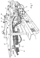
- Fig. 1 is a perspective view of the apparatus mounted on the movement system described in the aforesaid Italian patent;
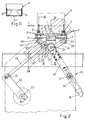
- Fig. 2 is a plan view from above and in partial section of the apparatus of Figure 1;
- Fig. 3 shows details of the apparatus according to the section III-III of Figure 2;
- Fig. 4 shows further details of the primary rotary joint of the apparatus of Figure 2, in section according to the line IV-IV;
- Fig. 5 shows, in a side view and in section according to the line III-III of Figure 2, one of the sliders supporting an adhesive-dispensing head;
- Fig. 6 shows, in plan view from above, one of the oscillating arms which carry the adhesive-dispensing heads;
- Fig. 7 shows, in partial vertical section, the primary rotary joint in a variant construction;
- Fig. 8 is a plan view from below of the primary rotary joint as shown in Figure 7;
- Fig. 9 is a side view of a variant construction of the apparatus in which the adhesive-dispensing heads are fixed directly to the oscillating arms;
- Fig. 10 is a schematic plan view from above of the variant shown in Figure 9;
- Fig. 11 shows schematically and in plan view a box with two strips of adhesive distributed by the apparatus in question.
- The following description relates to an apparatus for dispensing streams of adhesive orientated downwards, to be applied to the top of a box which is to be closed and which is arranged vertically, so that the terms "high", "low", "above" and "under" relate to this use of the apparatus. However, it should be understood that the apparatus can be used in an inverted configuration to distribute streams of adhesive on the lower part of a box to close it at the bottom and to prepare it for filling. As shown in Figures 1, 2 and 3, the apparatus comprises a straight guide 1 fixed in its mid-point under a
support 10 and provided with longitudinal slots 2-2' penetrated by pairs of screws 3-3' by which sliders 4-4' are fixed under the guide, with the possibility of adjustment of their distance from each other, these sliders, as shown in the example in Figure 5, having an L-shaped profile and carrying the frontally fixed adhesive-dispensingheads 5, 5' which are positioned vertically and orientated with their nozzles pointing downwards. Each head is connected to the control circuit of the moving element for opening and closing the nozzle, at the end of a corresponding channel 6 which is formed in each of thesaid sliders 4, 4' (Fig. 5), the channels being connected to compressed air supply ducts which can be shut off by electrically-operated valves 7, 7' (Fig. 1) which are fixed, for example, to thesupport 10. In Figure 5, thenumber 8 indicates a seat which is formed in each slider and which can house a resistor which keeps the slider at a predetermined temperature, controlled by means of a thermostatic probe located in theseat 9. Eachhead 5 is connected to the circuit for the passage of the adhesive at the end of acorresponding channel 11 opening into avertical hole 12, closed at the bottom, which is provided in each projectingpart 104, 104' of thesliders 4, 4', these parts being pivoted, for example, by means of secondary rotary joints D2, D2' with vertical axes (Fig. 2), on the ends ofarms 16, 16' which are provided withlongitudinal channels 17, 17' and whose other ends are, for example, pivoted on a primary rotary joint D1, also having a vertical axis, to which theflexible duct 55 for supplying the hot-melt adhesive is connected. As shown in Figures 1, 2 and 3, the joint D1 is provided with anannular recess 26 having at least one side flattened in the form of a secant 126 which interacts with ahorizontal fork 27 in such a way that it can slide longitudinally in the latter but cannot rotate, this fork being integral with the mid-point of the guide 1, perpendicular to it, and consequently fixed to thesupport 10. When thescrews 3, 3' are slackened, it is possible to modify the angular distance between thearms 16, 16' and consequently to adjust the distance between thesliders 4, 4' carrying the adhesive-dispensingheads 5, 5', with a self-centring movement with respect to theguide fork 27 on which the joint D1 slides longitudinally. - The secondary rotary joints D2, D2' are of a simplified type, with lateral seals, since their components rotate with respect to each other only during the adjustment of the distance between the
heads 5, 5', regardless of whether the apparatus is used in a static or dynamic way. As shown by the details in Figures 3, 4, 5 and 6, theblind holes 12 of the projectingpart 104, 104' of each slider are provided with intermediate threadedportions 112 and are provided with enlargedupper portions 212 in which are housed sealinggaskets 13 which surround the upper parts of the threaded terminal portions ofcorresponding screws 14 which are screwed and locked into thesaid holes 12 and which pass throughend holes 15 of thearms 16, 16', allowing these arms to oscillate with respect to the sliders. Theholes 15 are provided with intermediateannular recesses 19 into which thelongitudinal channels 17, 17' of thearms 16, 16' open, and which are also penetrated by intermediate portions of the saidscrews 14, 14', provided with T-shaped holes said recesses 19 to thechannels 11 of thesliders 4, 4'. Thechannel 11 which supplies the adhesive to the dispensingheads 5, 5' is thus connected to the longitudinal channels of thearms 16, 16' which can oscillate about the axis of thescrews 14.Annular sealing gaskets screws 14, are provided above and below theannular recess 19. - As shown in Figure 6, each
arm 16, 16' is provided with a correspondinglongitudinal seat 24 which houses an electrical heating resistor which is switched on and off as a shunt for the resistors for heating the aforesaid sliders and the principal joint D1 (see below). - If the apparatus is used in a static way, the primary rotary joint D1 can be of the same type as the aforesaid secondary joints D2, D2'. Conversely, if the apparatus is used in a dynamic way, as shown in Figures 1 and 2 and as stated above, the primary joint D1 is preferably of the type with frontal seals, as described above with reference to Figures 2, 3, 4 and 6. The
longitudinal channels 17, 17' of thearms 16, 16' open into corresponding end holes 18, 18' penetrated by thecylindrical shank 125 of a mushroom-shaped body 25 whosehead 225 is provided with the aforesaidannular recess 26 which interacts with theguide fork 27 used for the self-centring adjustment of the distance between thesliders 5, 5'. Awasher 70 and anelastic ring 71 axially retain thearms 16, 16' on theshank 125 of the mushroom-shaped body 25, which is provided at different heights withradial holes annular recesses arms 16, 16', with the provision of sealinggaskets shank 125 of the mushroom-shaped body, above and below the said recesses. In turn, the saidholes axial hole 32 of theshank 125 of the mushroom-shaped body, which opens in the head of the mushroom-shaped body in two portions whose diameter increases in the upward direction, and in the first of which is mounted the head of acylinder 33 which engages thesaid hole 32 with a lateral seal provided by anannular gasket 34, is pushed upward by aspring 35 with suitable characteristics positioned, for example, on the bottom of thesaid hole 32, and is prevented from rotating, for example by apin 72 which leaves the cylinder free to move axially. Thecylinder 33 is pierced axially as indicated by 37 and carries at its top an axial seat in which an annular insert 36 of hard metal, for example Widia, is fixed so that it partially projects. This insert is welded with a lateral seal into the seat of the cylinder, for example by braze welding, and is then ground on the frontal surface which can interact with anannual insert 38 having the same characteristics, which is welded with an exact degree of projection and with a lateral seal in an axial seat provided on the head of an inverted mushroom-shaped body 39 mounted rotatably in the upper seat of the mushroom-shaped body 25 by means of abearing 40 locked in place by means of the flange 225' which is fixed byscrews 41 and which forms part of thehead 225 of the said mushroom-shaped body 25. Theinsert 38 and the mushroom-shaped body 39 are penetrated axially by ahole 42 which is closed at the top and to which are connectedradial holes 43 which open into anannular recess 53 of the shank of the mushroom-shaped body 39 on which abody 45, fixed axially by means of thescrew 46, is mounted with the interposition of sealinggaskets 44. Thebody 45 is provided withseats arm 49, provided at its top with alongitudinal extension 50 slidable in aguide 51 supported with the possibility of rotation about a vertical axis by afixed plate 52, is fixed to thebody 45. The terminal portion of the flexible heated and thermostatically controlledduct 55, which supplies the hot-melt adhesive and which is connected to aradial hole 56 of thebody 45 communicating with the aforesaidannular recess 53, is fixed bysuitable means 54 to the saidarm 49. - As shown in Figures 1 and 2, the apparatus is used in a dynamic way and, for example, in the context of the system described in Italian patent no. 1,273,244 filed on 3 February 1994 in the name of SENZANI BREVETTI OFFICINE DI FAENZA S.R.L., the
support 10 is fixed under theslider 57 which slides on a pair of horizontalstraight guides 58 fixed under theplate 52 and orientated obliquely with respect to the straight arm of the transfer unit T along which the boxes A to be glued advance in single file. Thenumber 59 indicates the connecting rod one end of which is pivoted at 60 on theslider 57 while its other end is pivoted at 61 on acrank 62 keyed to avertical shaft 63 which is driven with an oscillating motion, in phase with the advance of the boxes A and at a speed such that the pair of adhesive-dispensingheads 5, 5' are made to undergo, cyclically, an oblique movement above or under the box to be closed, at a speed such that they follow the box in its advance in the direction indicated by the arrow F and also such that they move transversely with respect to the box to distribute two strips of adhesive S1, S1' on the box as shown in Figure 11. S2 indicates a further strip of adhesive distributed longitudinally on the moving box by a fixed dispensing head which is not illustrated in the drawings since it is not relevant to the understanding of the invention. The vertical axis 63 (Fig. 2) can form part of an oscillator, as specified in the patent cited above, or can form part of a movement system with an electric motor having electronically controlled speed and phase, for example with a brushless motor. - As shown in Figures 1 and 2, the
arm 49 with the adhesive-dispensingduct 55 is preferably placed at approximately 90° to theguides 58, in such a way that, during the reciprocating movement of theslider 57, the terminal part of theduct 55 is subjected to a minimum longitudinal movement and to an oscillation of small extent. - With reference to Figures 7 and 8, it will be seen that, according to a variant construction of the apparatus, the primary joint D1 can be provided with a part consisting of the shank of the
body 25 andlateral extensions 64, 64' provided with verticalblind holes 65, 65' to which are connectedinclined channels 66, 66' whose other ends communicate with theaxial hole 32 which in this case is closed below by acover 67 fixed withscrews 68 and with a sealinggasket 69. The ends of the longitudinallyhollow arms 16, 16' can be connected by secondary joints D3, D3', identical to the joints D2, D2' described above, to theaforesaid holes 65, 65', while their other ends are connected to thesliders 4, 4' in the way described or according to the aforesaid variant. Figure 7 shows how theinclined holes 66, 66' can be formed through theaxial hole 32, with thecover 67 removed, without emerging from theextensions 64, 64'. By removing thecover 67 it is also possible to gain direct access to thespring 35 to replace it, if necessary, during the maintenance of the apparatus. - Finally, in the variant shown in Figures 9 and 10 it can be seen that the
arms 16, 16' can be integral with, or formed in one piece with, thesliders 4, 4', which have an inverted L shape such that they are fixed by their upper parts to the slots of the straight guide 1 which is integral with thesupport 10 and is located in a position such that the theoretical vertical plane Q passing through the mid-line of the slots of this guide also contains the axis of the adhesive-dispensingheads 5, 5'. As shown in Figures 9 and 10, by slackening thescrews 3, 3' it is possible to vary the angular distance between thearms 16, 16' and therefore to adjust the distance between theheads 5, 5' as indicated by the arrows F5, thus keeping the heads on the said theoretical plane Q while the primary joint D1 moves towards or away from this theoretical plane as indicated by the arrows FD1.
Claims (15)
- Apparatus for forming a branched connection from a single duct for supplying adhesive, particularly hot-melt adhesive, to a pair of dispensing heads whose distance from each other can be adjusted for adaptation to different formats of boxes, characterized in that the heads (5, 5') are fixed on sliders (4, 4') mounted on the ends of arms (16, 16') whose other ends are pivoted on at least one common principal rotary joint (D1) to which is connected the flexible heated and thermostatically controlled duct (55) for supplying the hot-melt adhesive, the said arms being provided with longitudinal channels (17, 17') running from the said principal joint (D1) to channels in the sliders carrying the dispensing heads, the whole being arranged in such a way that by modifying the angular distance between the said arms it is possible to vary the distance between the adhesive-dispensing heads, to adapt the distance between the streams of adhesive supplied by these to the dimensions of the boxes to be glued.
- Apparatus according to Claim 1, characterized in that it is provided with means to ensure that the adjustment of the distance between the adhesive-dispensing heads takes place with a self-centring movement.
- Apparatus according to Claim 2, characterized in that the sliders (4, 4') carrying the adhesive-dispensing heads are movable on a straight guide (1) and are fixed in the desired position on this by screws (3, 3'), the said guide being fixed to the support (10) which holds the said apparatus, and a further guide (27), on which the principal rotary joint (D1) is slidably mounted, being integral with the first guide and perpendicular or orthogonal to its mid-line.
- Apparatus according to Claim 3, in which the guide (27) on which the principal rotary joint (D1) slides, consists of a fork which interacts with an annular recess (26) of the body of the said joint, this recess being provided with at least one flattened portion in the form of a secant (126) which interacts with at least one side of the said fork to prevent the rotation of the body of the joint.
- Apparatus according to Claim 2, in which the straight guide (1), on which the sliders (4, 4') carrying the adhesive-dispensing heads slide, is placed with its mid-line on a theoretical plane (Q) which contains the axes of the heads, the said sliders being shaped in such a way that they can interact with the said guide, and the said sliders being integral with, or made in one piece with, the longitudinally hollow arms (16, 16') connected directly or indirectly to the primary rotary joint (D1).
- Apparatus according to Claim 2, in which the straight guide (1), on which the sliders (4, 4') carrying the adhesive-dispensing heads slide, is placed laterally with respect to the heads, the said sliders being provided with hollow extensions (104, 104') which are pivoted on the ends of the said hollow arms (16, 16') by means of corresponding secondary rotary joints (D2, D2').
- Apparatus according to Claim 6, in which the secondary rotary joints (D2, D2') are of the type with lateral seals, while the primary rotary joint (D1) is of the type with frontal seals.
- Apparatus according to Claim 6, in which the extensions (104, 104') of the sliders (4, 4') are provided with threaded blind holes (12) which are enlarged at their tops to contain a sealing gasket (13), corresponding screws (14) being screwed into these holes and passing through corresponding end holes (15) of the arms (16, 16') with a lateral seal provided by gaskets (22, 23), these screws being provided with T-shaped channels (20, 21) which communicate below with the channels (11) of the said extensions and which communicate above with a annular recesses (19) which are provided in the screws, are delimited above and below by the said gaskets and are connected to the longitudinal channels (17, 17') of the arms.
- Apparatus according to Claim 1, in which the hollow arms (16, 16') for conveying the adhesive are pivoted, at one end in each case, on the axis of the principal rotary joint (D1), with the interposition of lateral seals (73, 74) and by means of annular recesses (30, 31) which act as collectors.
- Apparatus according to Claim 9, in which the principal rotary joint (D1) comprises a mushroom-shaped body (25) whose head carries externally the annular recess (26) which interacts with the fork-shaped guide (27) which provides the self-centring movement of the oscillating arm system for supplying the heads, the shank of the said mushroom-shaped body having pivoted on it the pierced ends (18) of the said hollow arms (16, 16') for conveying the adhesive, which are fixed axially by means of a washer (70) and an elastic ring (71), the said pierced ends of the arms being provided with annular recesses (30, 31) which are delimited above and below by sealing gaskets (73, 74) and which are connected to radial holes (28, 29) which open into an axial cavity (32) of the shank of the mushroom-shaped body, which is closed at the base and in which is housed at least one spring (35) which acts on the end of a small axially hollow piston (33) which is mounted with a lateral seal in the axial cavity of the said shank, is provided with a stop which limits its entry into this cavity and is provided axially with a seat in which a ring of hard metal (36) is housed with partial projection and is fixed with a lateral seal, this ring interacting with a similar ring (38) of hard metal fixed with a lateral seal and partial projection in a seat formed axially on the head of a second mushroom-shaped body (39) which is inverted and mounted rotatably in the head of the first mushroom-shaped body by means of at least one bearing (40) held in place by a flange (225') fixed by perimetrically placed screws (41), this latter mushroom-shaped body being provided with an axial hole (42) which communicates with radial holes (43) which in turn open into an annular recess (53) which is delimited above and below by sealing gaskets (44) and into which there opens a radial hole (56) formed in a body (45) fixed in this shank of the mushroom-shaped body and to which is connected the end of the flexible, heated and thermostatically controlled duct (55) for supplying the hot-melt adhesive.
- Apparatus according to Claim 10, in which the rings of hard metal (36, 38) which interact with each other with a frontal seal are made, for example, from Widia or equivalent material, and are welded perimetrically with a seal, for example by braze welding, into the seat which contains them and from which they partially project, these rings being subsequently ground on the surfaces intended to come into contact with each other.
- Apparatus according to Claim 10, in which the small piston (33) which carries one of the frontal sealing rings (36) and which is pushed axially by the spring (35) is provided with a means which prevents its rotation but not its axial movement, this means consisting, for example, of an eccentric pin (72).
- Apparatus according to Claim 10, characterized in that the body (45) to which the hot-melt adhesive supply duct (55) is connected carries a radially fixed arm (49) provided in its intermediate part with a longitudinal extension (50) which slides longitudinally in a small guide (51) mounted on a support (52) rotatable perpendicularly to the said extension, the terminal part of the said adhesive supply duct (55) being fixed on the said arm, the system being so designed that, if the apparatus is mounted on a rectilinear reciprocating motion system, the said arm (49) is orientated in such a way as to form an angle of approximately 90° to the rectilinear path of the apparatus.
- Apparatus according to Claim 10, characterized in that the hollow arms (16, 16') for conveying the adhesive to the heads are connected to the primary joint (D1) by means of corresponding secondary rotary joints (D3, D3') with lateral seals, located on lateral extensions (64, 64') of the body of the said primary joint which is closed below and with a seal by a cover (67) on which the spring (35) of the primary joint bears.
- Apparatus according to Claim 11, characterized in that the upper body (39) of the primary rotary joint (D1), the hollow arms (16, 16') which connect the said primary joint to the sliders (4, 4') carrying the adhesive-dispensing heads, and the sliders themselves are provided with corresponding seats (47, 24, 8) for housing electric heating resistors, seats (48, 9) being additionally provided at least in the first and the last of the said components for containing thermostatic probes which, by means of a control circuit, keep the temperature of the parts through which the adhesive passes at a level which ensures that the adhesive has the necessary fluidity.
Applications Claiming Priority (2)
| Application Number | Priority Date | Filing Date | Title |
|---|---|---|---|
| ITBO990397 | 1999-07-16 | ||
| IT1999BO000397A IT1309337B1 (en) | 1999-07-16 | 1999-07-16 | APPARATUS TO CONNECT A PAIR OF GLUE DISPENSING HEADS BY DERIVATION FROM A SINGLE POWER CONDUCT, |
Publications (1)
| Publication Number | Publication Date |
|---|---|
| EP1069045A1 true EP1069045A1 (en) | 2001-01-17 |
Family
ID=11344126
Family Applications (1)
| Application Number | Title | Priority Date | Filing Date |
|---|---|---|---|
| EP00114261A Withdrawn EP1069045A1 (en) | 1999-07-16 | 2000-07-04 | Apparatus for supplying adhesive to dispensing heads |
Country Status (2)
| Country | Link |
|---|---|
| EP (1) | EP1069045A1 (en) |
| IT (1) | IT1309337B1 (en) |
Cited By (4)
| Publication number | Priority date | Publication date | Assignee | Title |
|---|---|---|---|---|
| EP1240949A3 (en) * | 2000-12-04 | 2004-02-04 | Nordson Corporation | Device for dispensing fluids, particularly flowable adhesives |
| WO2005016556A1 (en) * | 2003-07-15 | 2005-02-24 | Kimberly-Clark Worldwide Inc. | Apparatus for depositing fluid material onto a substrate |
| CN104843238A (en) * | 2015-04-03 | 2015-08-19 | 李志峰 | Bonding assembly of broad bean packaging machine |
| EP3024588B1 (en) * | 2013-07-23 | 2018-03-14 | Focke & Co. (GmbH & Co.) | Apparatus to produce cigarettes packages with valves assembly |
Families Citing this family (1)
| Publication number | Priority date | Publication date | Assignee | Title |
|---|---|---|---|---|
| CN109018547A (en) * | 2018-07-18 | 2018-12-18 | 广州市凯安消防科技有限公司 | A kind of canister automation glue injection equipment of fire-fighting life-saving head-shield |
Citations (4)
| Publication number | Priority date | Publication date | Assignee | Title |
|---|---|---|---|---|
| EP0475224A2 (en) * | 1990-09-13 | 1992-03-18 | Nordson Corporation | Quick-adjusting, multiple dispenser positioner |
| EP0719591A2 (en) * | 1994-12-30 | 1996-07-03 | Nordson Corporation | Adhesive spray gun system with individually adjustable spray modules |
| ITBO950177U1 (en) | 1995-12-07 | 1997-06-07 | Senzani Brevetti Faenza Srl | APPARATUS FOR CONNECTING A COUPLE OF GLUE DISPENSING HEADS TO A SINGLE SUPPLY DUCT, |
| IT1273244B (en) | 1994-02-03 | 1997-07-07 | Senzani Brevetti Faenza Srl | Equipment for the leaktight fixing of closure flaps to the ends of containers or boxes, by means of jets of adhesive delivered partly to the flaps themselves in a transverse orientation to the direction of advance of the said boxes |
-
1999
- 1999-07-16 IT IT1999BO000397A patent/IT1309337B1/en active
-
2000
- 2000-07-04 EP EP00114261A patent/EP1069045A1/en not_active Withdrawn
Patent Citations (4)
| Publication number | Priority date | Publication date | Assignee | Title |
|---|---|---|---|---|
| EP0475224A2 (en) * | 1990-09-13 | 1992-03-18 | Nordson Corporation | Quick-adjusting, multiple dispenser positioner |
| IT1273244B (en) | 1994-02-03 | 1997-07-07 | Senzani Brevetti Faenza Srl | Equipment for the leaktight fixing of closure flaps to the ends of containers or boxes, by means of jets of adhesive delivered partly to the flaps themselves in a transverse orientation to the direction of advance of the said boxes |
| EP0719591A2 (en) * | 1994-12-30 | 1996-07-03 | Nordson Corporation | Adhesive spray gun system with individually adjustable spray modules |
| ITBO950177U1 (en) | 1995-12-07 | 1997-06-07 | Senzani Brevetti Faenza Srl | APPARATUS FOR CONNECTING A COUPLE OF GLUE DISPENSING HEADS TO A SINGLE SUPPLY DUCT, |
Cited By (4)
| Publication number | Priority date | Publication date | Assignee | Title |
|---|---|---|---|---|
| EP1240949A3 (en) * | 2000-12-04 | 2004-02-04 | Nordson Corporation | Device for dispensing fluids, particularly flowable adhesives |
| WO2005016556A1 (en) * | 2003-07-15 | 2005-02-24 | Kimberly-Clark Worldwide Inc. | Apparatus for depositing fluid material onto a substrate |
| EP3024588B1 (en) * | 2013-07-23 | 2018-03-14 | Focke & Co. (GmbH & Co.) | Apparatus to produce cigarettes packages with valves assembly |
| CN104843238A (en) * | 2015-04-03 | 2015-08-19 | 李志峰 | Bonding assembly of broad bean packaging machine |
Also Published As
| Publication number | Publication date |
|---|---|
| IT1309337B1 (en) | 2002-01-22 |
| ITBO990397A0 (en) | 1999-07-16 |
| ITBO990397A1 (en) | 2001-01-16 |
Similar Documents
| Publication | Publication Date | Title |
|---|---|---|
| US6012503A (en) | Adjustable gluing apparatus for a packaging machine | |
| EP1177053B1 (en) | Automated priming station | |
| US3831342A (en) | Method and apparatus for forming sift proof glued flap seals for cartons | |
| US4735169A (en) | Adhesive applicator assembly | |
| EP0497936B1 (en) | Apparatus for applying starch paste to tobacco articles | |
| US6607145B1 (en) | Spray gumming unit | |
| EP2923984B1 (en) | Cloth feed mechanism and cloth bonding apparatus | |
| EP1069045A1 (en) | Apparatus for supplying adhesive to dispensing heads | |
| JP2017221936A (en) | Glue application roller for use in gluing device equipped with at least one scooping roller | |
| KR920006489B1 (en) | Carton handle applicator | |
| EP0299592B1 (en) | Driving device and method for double bellows dispensing unit | |
| EP1798013B1 (en) | Glue distributing apparatus | |
| US5779854A (en) | Adhesive application device | |
| MXPA01010863A (en) | Automated adjustable gluing apparatus for a packaging machine. | |
| US5848738A (en) | Fill system including a fill pump disconnect system | |
| EP2253458B1 (en) | Cloth bonding apparatus | |
| WO2016202738A1 (en) | A glue application unit for a labeling apparatus | |
| US20030182904A1 (en) | Method and apparatus for applying glue to boxes | |
| EP0911085B1 (en) | A spray gumming unit | |
| US20240010482A1 (en) | Device for filling a container and method for operating the device | |
| JPH0691212A (en) | Label pasting device | |
| CN114104379B (en) | Iron adjusting mechanism | |
| KR20010085029A (en) | Tea bag packing machine | |
| CN210386392U (en) | Dispensing machine and dispensing assembly thereof | |
| US20040115346A1 (en) | Closure sealant dispenser |
Legal Events
| Date | Code | Title | Description |
|---|---|---|---|
| PUAI | Public reference made under article 153(3) epc to a published international application that has entered the european phase |
Free format text: ORIGINAL CODE: 0009012 |
|
| AK | Designated contracting states |
Kind code of ref document: A1 Designated state(s): AT BE CH CY DE DK ES FI FR GB GR IE IT LI LU MC NL PT SE |
|
| AX | Request for extension of the european patent |
Free format text: AL;LT;LV;MK;RO;SI |
|
| 17P | Request for examination filed |
Effective date: 20010221 |
|
| 17Q | First examination report despatched |
Effective date: 20010808 |
|
| AKX | Designation fees paid |
Free format text: AT BE CH CY DE DK ES FI FR GB GR IE IT LI LU MC NL PT SE |
|
| STAA | Information on the status of an ep patent application or granted ep patent |
Free format text: STATUS: THE APPLICATION IS DEEMED TO BE WITHDRAWN |
|
| 18D | Application deemed to be withdrawn |
Effective date: 20011209 |