EP1069035A1 - Motorbike transport case providing controlled movement of a closing mechanism - Google Patents
Motorbike transport case providing controlled movement of a closing mechanism Download PDFInfo
- Publication number
- EP1069035A1 EP1069035A1 EP00106134A EP00106134A EP1069035A1 EP 1069035 A1 EP1069035 A1 EP 1069035A1 EP 00106134 A EP00106134 A EP 00106134A EP 00106134 A EP00106134 A EP 00106134A EP 1069035 A1 EP1069035 A1 EP 1069035A1
- Authority
- EP
- European Patent Office
- Prior art keywords
- retaining member
- transport case
- motorbike
- base part
- lid part
- Prior art date
- Legal status (The legal status is an assumption and is not a legal conclusion. Google has not performed a legal analysis and makes no representation as to the accuracy of the status listed.)
- Granted
Links
- 230000007246 mechanism Effects 0.000 title claims abstract description 57
- 230000009471 action Effects 0.000 claims description 5
- 241000237983 Trochidae Species 0.000 description 7
- 238000010276 construction Methods 0.000 description 3
- 230000000994 depressogenic effect Effects 0.000 description 3
- 239000007787 solid Substances 0.000 description 2
- 230000000903 blocking effect Effects 0.000 description 1
- 230000008859 change Effects 0.000 description 1
- 230000000295 complement effect Effects 0.000 description 1
- 230000006835 compression Effects 0.000 description 1
- 238000007906 compression Methods 0.000 description 1
- 230000000694 effects Effects 0.000 description 1
- 230000002452 interceptive effect Effects 0.000 description 1
- 238000004519 manufacturing process Methods 0.000 description 1
- 230000009467 reduction Effects 0.000 description 1
Images



Classifications
-
- B—PERFORMING OPERATIONS; TRANSPORTING
- B62—LAND VEHICLES FOR TRAVELLING OTHERWISE THAN ON RAILS
- B62J—CYCLE SADDLES OR SEATS; AUXILIARY DEVICES OR ACCESSORIES SPECIALLY ADAPTED TO CYCLES AND NOT OTHERWISE PROVIDED FOR, e.g. ARTICLE CARRIERS OR CYCLE PROTECTORS
- B62J9/00—Containers specially adapted for cycles, e.g. panniers or saddle bags
- B62J9/30—Containers specially adapted for cycles, e.g. panniers or saddle bags characterised by locking arrangements, e.g. top case locks integrated in a vehicle central locking system
-
- B—PERFORMING OPERATIONS; TRANSPORTING
- B62—LAND VEHICLES FOR TRAVELLING OTHERWISE THAN ON RAILS
- B62J—CYCLE SADDLES OR SEATS; AUXILIARY DEVICES OR ACCESSORIES SPECIALLY ADAPTED TO CYCLES AND NOT OTHERWISE PROVIDED FOR, e.g. ARTICLE CARRIERS OR CYCLE PROTECTORS
- B62J9/00—Containers specially adapted for cycles, e.g. panniers or saddle bags
- B62J9/20—Containers specially adapted for cycles, e.g. panniers or saddle bags attached to the cycle as accessories
- B62J9/27—Containers specially adapted for cycles, e.g. panniers or saddle bags attached to the cycle as accessories characterised by mounting arrangements, e.g. quick release arrangements
-
- B—PERFORMING OPERATIONS; TRANSPORTING
- B62—LAND VEHICLES FOR TRAVELLING OTHERWISE THAN ON RAILS
- B62J—CYCLE SADDLES OR SEATS; AUXILIARY DEVICES OR ACCESSORIES SPECIALLY ADAPTED TO CYCLES AND NOT OTHERWISE PROVIDED FOR, e.g. ARTICLE CARRIERS OR CYCLE PROTECTORS
- B62J9/00—Containers specially adapted for cycles, e.g. panniers or saddle bags
- B62J9/20—Containers specially adapted for cycles, e.g. panniers or saddle bags attached to the cycle as accessories
- B62J9/21—Containers specially adapted for cycles, e.g. panniers or saddle bags attached to the cycle as accessories above or alongside the front wheel, e.g. on the handlebars
-
- B—PERFORMING OPERATIONS; TRANSPORTING
- B62—LAND VEHICLES FOR TRAVELLING OTHERWISE THAN ON RAILS
- B62J—CYCLE SADDLES OR SEATS; AUXILIARY DEVICES OR ACCESSORIES SPECIALLY ADAPTED TO CYCLES AND NOT OTHERWISE PROVIDED FOR, e.g. ARTICLE CARRIERS OR CYCLE PROTECTORS
- B62J9/00—Containers specially adapted for cycles, e.g. panniers or saddle bags
- B62J9/20—Containers specially adapted for cycles, e.g. panniers or saddle bags attached to the cycle as accessories
- B62J9/23—Containers specially adapted for cycles, e.g. panniers or saddle bags attached to the cycle as accessories above or alongside the rear wheel
Definitions
- the invention relates to a motorbike transport case comprising:
- a motorbike transport case of this type is described in the applicant's previous patent EP-B1-0517 265, for example, and in the applicant's earlier European patent application 99123097.0 (filed on 22.11.99 but not published before the filing date of the subject invention).
- transport cases that can be fitted detachably to a motorbike provide versatility in that the user may employ such a case either separately from a motorbike, e.g. while walking as a pedestrian or working in an office, or in a fitted state, i.e. when driving a motorbike to which the transport case has been fitted so that the user does not have to hold the case manually.
- the retaining member is arranged to move vertically up (from a first to a second position) and down (from the second to the first position) to open and close the transport case, respectively.
- a hook-shaped profile thereof may not be engaging the lid part (e.g. an edge thereof) even though the retaining member has been moved to the first position.
- the transport case is not firmly closed although the user has brought the retaining member to the first position which normally serves to hold the lid part to the base part of the transport case.
- the retaining member has reached the second position, the user may erroneously assume that the transport case is securely closed when in reality it is not.
- Driving a motorbike with a loose lid part of the transport case may result in objects being lost from the transport case on the road.
- the retaining member may be locked (e.g. by turning a key) in the first position even where the retaining member does not actually hold the lid part to the base part of the transport case.
- the user may therefore erroneously assume that the transport case is closed and locked up when in reality it is not. Parking a motorbike with an unsecured lid part of the transport case may result in objects being stolen from the transport case due to insufficient or negligent closing before locking.
- control mechanism allows the retaining member to be brought from the second position to the first position only in such a manner that the retaining member actually holds the lid part to the base part when the retaining member has reached the first position.
- Movement of the retaining member is limited by the control mechanism such that the retaining member can be brought to the first position only after the retaining member has been oriented to join the lid and base parts of the transport case.
- the user is effectively reminded to apply the retaining member properly to the part to be engaged (normally the lid part) before he/she brings the retaining member to the first position in which the retaining member will hold the lid and base parts together. In other words, the user cannot bring the retaining member to the first position without fastening the lid part to the base part.
- the retaining member is arranged to be returned automatically e.g. by a return spring, to the second position of the transport case has not been closed properly. Return movement of the retaining member will draw the user's attention to the fact that the transport case has not been closed properly.
- the retaining member may be secured to either transport case part (base part or lid part) and arranged to selectively engage and release the other part when the retaining member is in the first or second position, respectively.
- the retaining member is secured to the base part and arranged to engage and release the lid part.
- the retaining member may comprise a hook-shaped end adapted to engage an edge of the lid part.
- the retaining member is articulated to the base part and, in the second position, can be pivoted selectively towards the lid part to engage it and away from the lid part to release it, and the control mechanism allows the retaining member to be brought from the second position to the first position only when the retaining member has been pivoted towards the lid part.
- a pivotable structure of the retaining member advantageously defines two clear situations which the control mechanism can distinguish in order to allow or prevent movement of the retaining member into the second position thereof.
- the retaining member may be moved between its first and second position by exerting manual pressure and/or a frictional force directly on the retaining member.
- the control mechanism comprises a specific opening means, in particular in the form of a push button, which is operable to bring the retaining member from the first position to the second position.
- operation of the opening means may snap the retaining member out of the first position so that the user can shift the retaining member to the second position.
- operation of the opening means may release a spring that automatically urges the retaining member to the second position.
- a push button or other compact opening means that acts on the retaining member (to bring it to the second position) is an advantageous aspect of the invention which may be realised irrespective of whether or not a control mechanism is arranged to limit the return movement of the retaining member (i.e. when returning to the first position).
- a push button or other compact opening means (rather than a pivotable locking plate as the one used in EP-B1-0 517 265) enables a particularly compact and tamper-proof design of the closing mechanism.
- the opening means is in a first state when the retaining member is in the first position, and the opening means is in a second state when the retaining member is in the second position.
- the state of the opening means advantageously indicates the state of the retaining member.
- a push button acting as the opening means may project from the base part only when the retaining member is in the first position. The push button may be depressed to bring the retaining member to the second position (in order to open the transport case) and will keep the depressed state as long as the retaining member is in the second position.
- the push button is returned to its projecting state indicating that the retaining member has properly assumed the first position.
- the user knows that the transport case has not been closed correctly.
- the information to the user may be enhanced by tactile or acoustic feedback, e.g. by a snap action of the control mechanism and/or push button (or other opening means) when the retaining member is returned properly to the first position.
- control mechanism or an opening means acting on the control mechanism may be selectively locked and unlocked, preferably by turning a (mechanical) key in a lock.
- operation of the lock may require some special tool, combination code number, electronic key or the like.
- the lock may be preferably arranged to release the key only in the locked state so that the user is reminded to lock the transport case before he/she can withdraw the key.
- a push button represents an advantageous implementation of the opening means in that it allows a simple, solid and compact construction of the opening/closing apparatus comprising the retaining member and control mechanism.
- the opening/closing apparatus may comprise fewer components, is easy to manufacture and provides enhanced security because the solid and compact construction of the opening/closing apparatus is less vulnerable to burglary.
- the motorbike transport case may be arranged (in a manner known per se) such that
- a lock e.g. a key-operated lock
- a lock is preferably provided for selectively locking and unlocking the control mechanism or an opening means acting on the control mechanism.
- Another lock or preferably the same lock may be advantageously used to selectively lock'and unlock the fitting latch or the detaching means acting on the fitting latch.
- operation of a single lock secures both the transport case to a motorbike and the lid part to the base part, thus preventing unauthorised persons from detaching and/or opening the transport case.
- a single lock is used that has only two positions: a locked position and an unlocked position. In the locked position, the transport case cannot be detached nor opened. In the unlocked position, the transport case can be detached and/or opened.
- the key can be withdrawn only in the locked position of the lock.
- a single lock is used that has at least three positions: a locked position, a partially unlocked position, and a completely unlocked position.
- the transport case cannot be detached nor opened.
- the transport case In the partially unlocked position, the transport case can be opened but cannot be detached (or can be detached but cannot be opened).
- the completely unlocked position the transport case can be opened and/or detached.
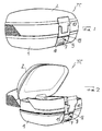
- a transport case TC as illustrated schematically in Figure 1 can be fitted detachably on a support structure 3 of a motorbike (the term motorbike including motorscooters).
- the transport case TC is fitted preferably on the top surface of a support structure, as shown in Figures 3 and 5, for example.
- the transport case TC may also be referred to as a top case.
- the transport case TC comprises a base part 1 which may be referred to as the bottom half-shell (assuming that the base part 1 is the lower part of a top mounted transport case), or just bottom shell.
- the transport case TC further comprises a lid part 2 which may be referred to as the top half-shell (assuming that the lid part 2 is the upper part of a top mounted transport case), or just top shell.
- the term "half-shell" as used herein does not imply that the lower and upper parts 1 and 2 of the transport case TC have to have the same size.
- the base part 1 is shown to be fitted substantially horizontally to the support structure 3 of the motorbike, the subject application also contemplates alternative arrangements in which the base part 1 may be fitted in any other orientation, e.g. to a substantially vertical structure of the motorbike.
- the lid part may be hinged to the base part such that the lid part is pivotable about a horizontal axis or a vertical axis.
- the transport case is not restricted to being fitted to the rear structure of a motorbike.
- the invention also contemplates transport cases for use on lateral or front structures of a motorbike.
- the transport case may comprise a retractable handle 19.
- the lid part 2 may be hinged to the base part 1 such that the transport case (top case) TC can be opened by pivoting the lid part 2 upwardly from the base part 1 once a locking mechanism has been unlocked and a closing mechanism has been opened (as described in greater detail below).
- the transport case TC can be closed by pivoting the lid part 2 downwardly onto the base part 1 where the lid part 2 can be held by a retaining member of the closing mechanism and locked by the locking mechanism.
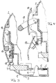
- a conventional closing mechanism (EP-B1-0 517 265), as best shown in Figures 3 and 4, comprises a retaining member 10 which in a first or closed position ( Figure 3) holds the lid part 2 to the base part 1 of the transport case.
- the end portion of the retaining member may be hook-shaped (in cross-section) to engage a corresponding edge of the lid part 2.
- a locking plate 18 is pivoted upwardly (away from base part 1), the retaining member is lifted to a second or open position ( Figure 4) in which the user can release the retaining member from the edge of lid part 2 to open the transport case.
- the conventional closing mechanism has a complicated and fragile structure (comprising various hinges and a locking plate in addition to the retaining member) and is thus vulnerable to violence by a burglar. Further, when the closing mechanism is to be closed by lowering the locking plate and the retaining member, the retaining member may not be engaging the edge of lid part 2 although the retaining member as such has been lowered to the first position. Consequently, the transport case may not be firmly closed if a user inadvertently lowers the locking plate and retaining member without pressing the hook-shaped end of the retaining member properly onto the engagement edge of lid part 2.
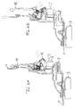
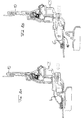
- Figure 5 is a sectional view of a closing mechanism according to the present invention, with the closing mechanism being in a first (or closed) state in which a retaining member 10 is seated in a first (or closed or lower) position and holds the lid part 2 to the base part 1 of the transport case.
- a preferably hook-shaped end of the retaining member 10 engages a complementary edge of the lid part 2.
- the user manually depresses a push button 12 (as indicated by an arrow) which causes the retaining member 10 to be lifted to a second (or upper or open) position where the hook-shaped end of the retaining member 10 can be disengaged, e.g. pivoted, from the edge of lid part 2.
- the disengaging movement may be achieved automatically if the retaining member 10 is spring-loaded (e.g. by a torsion spring 15 or a pair of torsion springs 15) and if depression of the push button 12 releases the retaining member 10 from a snapped-in position, for example.
- the retaining member 10 In order to close the transport case ( Figures 7A and 7B), the retaining member 10 has to be returned to its first (or lower) position.
- the retaining member 10 starting from the situation shown in Figure 6B cannot be shifted immediately downwards to the lower position because the control mechanism that determines the path of travel of the retaining member 10 is arranged to prevent downward movement of the retaining member 10 unless the latter has pivoted back toward the lid part 2 to engage the edge thereof.
- the skilled person is able to limit the downward movement of the retaining member 10 in various ways.
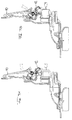
- the user first has to pivot the retaining member 10 towards the lid part 2 (arrow in Figure 7A) so that the upper end of the retaining member 10 abuts on the lid part 2. Only then can the retaining member 10 be urged back to its first (or lower) position by applying a manual force along the arrow indicated in Figure 7B to finally return to the first position shown in Figure 5.
- the push button 12 projects outwardly from a rear wall 8 of the base part 1 when the retaining member 10 is in the first position ( Figure 5).
- the push button 12 projects to a smaller extent ( Figure 6A) or may be even flush with said rear wall 8 ( Figure 6B), thus indicating that the retaining member 10 is not seated in the first position.
- the push button 12 is urged outwardly to its maximum projection ( Figure 5), thus indicating visually that the retaining member 10 is actually seated in the first position.
- a snap action of the closing mechanism and/or push button 12 may occur when the retaining member 10 is being received in the first position. In that case, an acoustic and/or tactile feedback is provided to the user so that he/she knows that the retaining member 10 has returned completely to the first position.
- the push button 12 for opening the transport case is secured by a lock 9 which may be operated by an associated key.
- the lock 9 prevents the push button 12 from being pushed through the rear wall 8. In other words, the retaining member 10 cannot be shifted upwardly to open the transport case.
- the lock 9 allows the push button 12 to be pushed through the rear wall 8 to release the retaining member 10 and to open the transport case.
- the lock receiving the key is arranged such that the key has to be rotated through a large angle, e.g. approximately 90°, in order to switch the lock from the locked state to the unlocked state.
- the angle is chosen to be approximately 90°, the unlocking position of the key is transverse to the locking position of the key, which makes it particularly easy and reliable for the user to distinguish the positions of the key and, thus, to recognise the current state and function of the lock.
- the base part 1 (bottom shell) is fitted horizontally to the support structure 3 of the motorbike.
- the support structure 3 may be formed by a rack of the motorbike itself or by a standardised carrier plate additionally mounted on (possibly retrofitted to) the motorbike.
- the support structure 3 and base part 1 are arranged to mate each other so that the base part 1 can be fitted and secured to the support structure 3.
- the support structure 3 may comprise a conventional fitting extension 4 protruding vertically from the upper surface of the support structure 3 and adapted to be received in a base aperture 16 of the bottom wall of the base part 1, as shown in Figures 3 and 5, for example.
- a latch 6 is provided above the bottom aperture 16 in base part 1 and biased by at least one compression spring 5 to catch the fitting extension 4 in the bottom aperture 16.
- a (second) push button 7 may be arranged to urge the latch 6 away from the fitting extension 4 so that the transport case is released from the support structure 3.
- a locking mechanism may be provided to lock the latch 6 in the position catching the fitting extension 4 so that the transport case TC cannot be detached from the support structure 3 by an unauthorised person.
- it is the lock 9 that serves not only to lock the push button 12 for opening the transport case but also to lock the transport case to the fitting extension 4 of a motorbike or carrier plate to which the transport case may be fitted.
- the lock 9 prevents both push buttons 7 and 12 from moving in their respective guide structures.
- the key is rotated through 90° ( Figures 6A and 8A)
- each of the push buttons 7 and 12 can be depressed.
- Pushing button 7 releases latch 6 from fitting extension 4 so that the transport case can be detached from the support structure 3 of the motorbike ( Figure 8B).
- either a horizontal or a vertical wall of the base part may be fitted to the motorbike.
- the wall of the base part fitted to the motorbike constitutes the "bottom portion" within the meaning of the preceding description. Therefore, the term “bottom portion” is not limited to a lower horizontal wall of the base part.
- the base part and lid part may be arranged either above or beside each other, with the base part being mounted to a support structure (e.g. the rack or an intermediate carrier plate) of the motorbike and the lid part being pivotable with respect to the base part.
- the two-position lock 9 comprises an inner lock part 13.
- the upper part of rear wall 8 carries two wings 20 provided with openings; in these openings there is inserted a pin around which are hinged the opening button 12 and a small connecting rod 11.
- the small connecting rod 11 has two pairs of holes; through the first pair of holes 22 passes the pin around which is hinged also the opening button 12, while in the second pair of holes 23 is inserted another pin to which is hinged the retaining member 10.
- In the upper part of the retaining member 10 there is a tooth 24 which fits a counter-tooth 25 in the lid part 2 and permits the closure of the topcase.
- the closing mechanism is also provided with two torsion springs 14 and 15 which support the operation; the spring 14 is fixed between the rear wall 8 and the small connecting rod 11 while the spring 15 is fixed between the small connecting rod 11 and the retaining member 10.
- the closing mechanism is provided with a lock 9 preferably having a two-position key, which thus permits two different forms of use of the closing mechanism.
- the lock With the key in vertical position, the lock is in closed position (see Figure 5), and this makes it impossible to open the transport case and to detach it from the support structure on the motorcycle.
- the transport case cannot be opened because ribs 26 and 27 of the inner lock 13 act respectively on a tooth 28 of the opening button 12 and a tooth 29 of the small connecting rod 11.
- ribs 26 and 27 of the inner lock 13 act respectively on a tooth 28 of the opening button 12 and a tooth 29 of the small connecting rod 11.
- the interference between the rib 26 and the tooth 28 prevents operation of the opening button 12 and consequently does not allow any movement of the retaining member 10 and of the small connecting rod 11 connected to the retaining member 10.
- the locking of the rib 27 on the tooth 29 and consequently of the small connecting rod 11 is an important feature because it is the movement of the small connecting rod that allows the complete movement of the retaining member 10.
- the unlocked position is obtained by turning the key about 90° from the locked position (see e.g. Figure 6A); positioning of the key is ensured by a spring system which allows the user to immediately identify the principal positions of the key (0° and 90° positions).
- a spring system which allows the user to immediately identify the principal positions of the key (0° and 90° positions).
- the retaining member 10 has a further rib 39, if the engagement is not correct this rib interferes with the upper part 40 of the rear wall 8 bringing the retaining member 10 back to vertical position.
Landscapes
- Engineering & Computer Science (AREA)
- Mechanical Engineering (AREA)
- Closures For Containers (AREA)
- Lock And Its Accessories (AREA)
- Purses, Travelling Bags, Baskets, Or Suitcases (AREA)
- Fittings On The Vehicle Exterior For Carrying Loads, And Devices For Holding Or Mounting Articles (AREA)
- Axle Suspensions And Sidecars For Cycles (AREA)
- Physical Deposition Of Substances That Are Components Of Semiconductor Devices (AREA)
- Sampling And Sample Adjustment (AREA)
Abstract
Description
- The invention relates to a motorbike transport case comprising:
- a base part arranged to be detachably fitted to a motorbike or a carrier plate mounted on a motorbike (the term "motorbike" as used in this specification encompassing motor scooters);
- a lid part hinged to the base part such that the lid part can be pivoted away from the base part to open the transport case and pivoted toward the base part to close the transport case;
- a retaining member arranged to selectively assume a first position, in which the retaining member can hold the lid part to the base part, and a second position, in which the retaining member cannot hold the lid part to the base part; and
- a control mechanism for bringing the retaining member from the first position to the second position.
- A motorbike transport case of this type is described in the applicant's previous patent EP-B1-0517 265, for example, and in the applicant's earlier European patent application 99123097.0 (filed on 22.11.99 but not published before the filing date of the subject invention).
- As has been well-known in the art, transport cases that can be fitted detachably to a motorbike provide versatility in that the user may employ such a case either separately from a motorbike, e.g. while walking as a pedestrian or working in an office, or in a fitted state, i.e. when driving a motorbike to which the transport case has been fitted so that the user does not have to hold the case manually.
- While the conventional detachable transport case thus provides considerable convenience to the user, the following problem may arise during closing of the transport case. In the prior art transport case, the retaining member is arranged to move vertically up (from a first to a second position) and down (from the second to the first position) to open and close the transport case, respectively. In the second position, the retaining member can be pivoted through a relatively wide angle with respect to the lid parts. Consequently, when the retaining member is brought from the second (upper) position (= open transport case) to the first (lower) position (in which the transport case is supposed to be closed), inadvertent operation may result in the retaining member still not holding the lid part to the base part, because the retaining member (e.g. a hook-shaped profile thereof) may not be engaging the lid part (e.g. an edge thereof) even though the retaining member has been moved to the first position. In other words, the transport case is not firmly closed although the user has brought the retaining member to the first position which normally serves to hold the lid part to the base part of the transport case. As the retaining member has reached the second position, the user may erroneously assume that the transport case is securely closed when in reality it is not. Driving a motorbike with a loose lid part of the transport case may result in objects being lost from the transport case on the road.
- Further, the retaining member may be locked (e.g. by turning a key) in the first position even where the retaining member does not actually hold the lid part to the base part of the transport case. The user may therefore erroneously assume that the transport case is closed and locked up when in reality it is not. Parking a motorbike with an unsecured lid part of the transport case may result in objects being stolen from the transport case due to insufficient or negligent closing before locking.
- Therefore, it is an object of the application to provide a motorbike transport case of the abovementioned type which obviates a user's negligence during closing of the transport case.
- According to the invention, this object is achieved by the following additional feature: The control mechanism allows the retaining member to be brought from the second position to the first position only in such a manner that the retaining member actually holds the lid part to the base part when the retaining member has reached the first position.
- Movement of the retaining member is limited by the control mechanism such that the retaining member can be brought to the first position only after the retaining member has been oriented to join the lid and base parts of the transport case. In this advantageous manner, the user is effectively reminded to apply the retaining member properly to the part to be engaged (normally the lid part) before he/she brings the retaining member to the first position in which the retaining member will hold the lid and base parts together. In other words, the user cannot bring the retaining member to the first position without fastening the lid part to the base part.
- In a preferred embodiment, the retaining member is arranged to be returned automatically e.g. by a return spring, to the second position of the transport case has not been closed properly. Return movement of the retaining member will draw the user's attention to the fact that the transport case has not been closed properly.
- Generally, the retaining member may be secured to either transport case part (base part or lid part) and arranged to selectively engage and release the other part when the retaining member is in the first or second position, respectively. In a presently preferred embodiment, however, the retaining member is secured to the base part and arranged to engage and release the lid part. For this purpose, the retaining member may comprise a hook-shaped end adapted to engage an edge of the lid part.
- In a particularly preferred embodiment, the retaining member is articulated to the base part and, in the second position, can be pivoted selectively towards the lid part to engage it and away from the lid part to release it, and the control mechanism allows the retaining member to be brought from the second position to the first position only when the retaining member has been pivoted towards the lid part. Such a pivotable structure of the retaining member advantageously defines two clear situations which the control mechanism can distinguish in order to allow or prevent movement of the retaining member into the second position thereof.
- Generally, the retaining member may be moved between its first and second position by exerting manual pressure and/or a frictional force directly on the retaining member. However, in an advantageous implementation of the motorbike transport case, the control mechanism comprises a specific opening means, in particular in the form of a push button, which is operable to bring the retaining member from the first position to the second position. For example, operation of the opening means may snap the retaining member out of the first position so that the user can shift the retaining member to the second position. Alternatively, operation of the opening means may release a spring that automatically urges the retaining member to the second position.
- The concept of using a push button or other compact opening means that acts on the retaining member (to bring it to the second position) is an advantageous aspect of the invention which may be realised irrespective of whether or not a control mechanism is arranged to limit the return movement of the retaining member (i.e. when returning to the first position). Using a push button or other compact opening means (rather than a pivotable locking plate as the one used in EP-B1-0 517 265) enables a particularly compact and tamper-proof design of the closing mechanism.
- In a particularly preferred embodiment, the opening means is in a first state when the retaining member is in the first position, and the opening means is in a second state when the retaining member is in the second position. In this manner, the state of the opening means advantageously indicates the state of the retaining member. For example, a push button acting as the opening means may project from the base part only when the retaining member is in the first position. The push button may be depressed to bring the retaining member to the second position (in order to open the transport case) and will keep the depressed state as long as the retaining member is in the second position. When the retaining member is brought back to the first position, the push button is returned to its projecting state indicating that the retaining member has properly assumed the first position. If the push button does not project from the base part, the user knows that the transport case has not been closed correctly. The information to the user may be enhanced by tactile or acoustic feedback, e.g. by a snap action of the control mechanism and/or push button (or other opening means) when the retaining member is returned properly to the first position.
- Preferably, the control mechanism or an opening means acting on the control mechanism may be selectively locked and unlocked, preferably by turning a (mechanical) key in a lock. Alternatively, operation of the lock may require some special tool, combination code number, electronic key or the like. Where a mechanical key is used, the lock may be preferably arranged to release the key only in the locked state so that the user is reminded to lock the transport case before he/she can withdraw the key.
- A push button represents an advantageous implementation of the opening means in that it allows a simple, solid and compact construction of the opening/closing apparatus comprising the retaining member and control mechanism. The opening/closing apparatus may comprise fewer components, is easy to manufacture and provides enhanced security because the solid and compact construction of the opening/closing apparatus is less vulnerable to burglary.
- In order to fit the transport case to a motorbike (or to a carrier plate mounted on a motorbike), the motorbike transport case may be arranged (in a manner known per se) such that
- a wall portion of the base part comprises an aperture for receiving a fitting extension of a support structure of a motorbike;
- the base part comprises a fitting latch arranged to couple the base part to a received fitting extension; and
- the base part comprises a detaching means, in particular a push button, arranged to release the fitting latch from a received fitting extension.
- As mentioned above, a lock (e.g. a key-operated lock) is preferably provided for selectively locking and unlocking the control mechanism or an opening means acting on the control mechanism. Another lock or preferably the same lock may be advantageously used to selectively lock'and unlock the fitting latch or the detaching means acting on the fitting latch. Preferably, operation of a single lock secures both the transport case to a motorbike and the lid part to the base part, thus preventing unauthorised persons from detaching and/or opening the transport case. In a particularly preferred arrangement, a single lock is used that has only two positions: a locked position and an unlocked position. In the locked position, the transport case cannot be detached nor opened. In the unlocked position, the transport case can be detached and/or opened. Preferably, the key can be withdrawn only in the locked position of the lock. In an alternative arrangement, a single lock is used that has at least three positions: a locked position, a partially unlocked position, and a completely unlocked position. In the locked position, the transport case cannot be detached nor opened. In the partially unlocked position, the transport case can be opened but cannot be detached (or can be detached but cannot be opened). In the completely unlocked position, the transport case can be opened and/or detached.
- Further features and advantages of the invention will become apparent from the description of a preferred embodiment given below with reference to the accompanying drawings wherein
- Figure 1 is a perspective view of a conventional motorbike transport case in the closed state thereof;
- Figure 2 is a perspective view of the conventional transport case in the open state thereof;
- Figure 3 is a sectional view of a closing mechanism of the conventional transport case, with the closing mechanism being in a first (or closed) state in which a retaining member holds a lid part to a base part of the transport case;
- Figure 4 is a another sectional view of the closing mechanism of the conventional transport case, with the closing mechanism being in a second (or open) state in which the retaining member does not hold the lid part to the base part of the transport case;
- Figure 5 is a sectional view of a closing mechanism according to the present invention, with the closing mechanism being in a first (or closed) state in which a retaining member holds a lid part to a base part of the transport case;
- Figures 6A and 6B are sectional views of the closing mechanism according to the invention, with the closing mechanism being opened in two steps so that the retaining member is brought to a second position in which the retaining member does not hold the lid part to the base part of the transport case;
- Figures 7A and 7B are sectional views of the closing mechanism according to the invention, with the closing mechanism being closed in two steps so that the retaining member is returned to the first position in which the retaining member holds the lid part to the base part of the transport case;
- Figures 8A and 8B are sectional views of the closing mechanism according to the invention, wherein a latch is released to detach the transport case from a support structure of a motorbike.
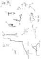
- Figures 9A to 9C are detailed views of individual components of the closing mechanism.
-
- A transport case TC as illustrated schematically in Figure 1 can be fitted detachably on a
support structure 3 of a motorbike (the term motorbike including motorscooters). The transport case TC is fitted preferably on the top surface of a support structure, as shown in Figures 3 and 5, for example. In that arrangement, the transport case TC may also be referred to as a top case. The transport case TC comprises abase part 1 which may be referred to as the bottom half-shell (assuming that thebase part 1 is the lower part of a top mounted transport case), or just bottom shell. The transport case TC further comprises alid part 2 which may be referred to as the top half-shell (assuming that thelid part 2 is the upper part of a top mounted transport case), or just top shell. Incidentally, the term "half-shell" as used herein does not imply that the lower andupper parts base part 1 is shown to be fitted substantially horizontally to thesupport structure 3 of the motorbike, the subject application also contemplates alternative arrangements in which thebase part 1 may be fitted in any other orientation, e.g. to a substantially vertical structure of the motorbike. In either case, the lid part may be hinged to the base part such that the lid part is pivotable about a horizontal axis or a vertical axis. Likewise, the transport case is not restricted to being fitted to the rear structure of a motorbike. The invention also contemplates transport cases for use on lateral or front structures of a motorbike. - Referring to Figures 1 and 4, the transport case may comprise a
retractable handle 19. With further reference to Figure 2, thelid part 2 may be hinged to thebase part 1 such that the transport case (top case) TC can be opened by pivoting thelid part 2 upwardly from thebase part 1 once a locking mechanism has been unlocked and a closing mechanism has been opened (as described in greater detail below). Conversely, the transport case TC can be closed by pivoting thelid part 2 downwardly onto thebase part 1 where thelid part 2 can be held by a retaining member of the closing mechanism and locked by the locking mechanism. - A conventional closing mechanism (EP-B1-0 517 265), as best shown in Figures 3 and 4, comprises a retaining
member 10 which in a first or closed position (Figure 3) holds thelid part 2 to thebase part 1 of the transport case. For this purpose, the end portion of the retaining member may be hook-shaped (in cross-section) to engage a corresponding edge of thelid part 2. When a lockingplate 18 is pivoted upwardly (away from base part 1), the retaining member is lifted to a second or open position (Figure 4) in which the user can release the retaining member from the edge oflid part 2 to open the transport case. The conventional closing mechanism has a complicated and fragile structure (comprising various hinges and a locking plate in addition to the retaining member) and is thus vulnerable to violence by a burglar. Further, when the closing mechanism is to be closed by lowering the locking plate and the retaining member, the retaining member may not be engaging the edge oflid part 2 although the retaining member as such has been lowered to the first position. Consequently, the transport case may not be firmly closed if a user inadvertently lowers the locking plate and retaining member without pressing the hook-shaped end of the retaining member properly onto the engagement edge oflid part 2. - In the following, an exemplary implementation of the closing and locking mechanisms of the transport case TC of the invention will be described in greater detail. Like parts are denoted by same reference numerals throughout the description. For clarity and completeness, the various components constituting the closing and locking mechanisms are also shown individually in Figures 9A, 9B and 9C.
- Figure 5 is a sectional view of a closing mechanism according to the present invention, with the closing mechanism being in a first (or closed) state in which a retaining
member 10 is seated in a first (or closed or lower) position and holds thelid part 2 to thebase part 1 of the transport case. For this purpose, a preferably hook-shaped end of the retainingmember 10 engages a complementary edge of thelid part 2. - According to one aspect of the invention, in order to open the transport case (Figures 6A and 6B), the user manually depresses a push button 12 (as indicated by an arrow) which causes the retaining
member 10 to be lifted to a second (or upper or open) position where the hook-shaped end of the retainingmember 10 can be disengaged, e.g. pivoted, from the edge oflid part 2. The disengaging movement may be achieved automatically if the retainingmember 10 is spring-loaded (e.g. by atorsion spring 15 or a pair of torsion springs 15) and if depression of thepush button 12 releases the retainingmember 10 from a snapped-in position, for example. - In order to close the transport case (Figures 7A and 7B), the retaining
member 10 has to be returned to its first (or lower) position. In accordance with another major aspect of the invention, the retainingmember 10 starting from the situation shown in Figure 6B cannot be shifted immediately downwards to the lower position because the control mechanism that determines the path of travel of the retainingmember 10 is arranged to prevent downward movement of the retainingmember 10 unless the latter has pivoted back toward thelid part 2 to engage the edge thereof. The skilled person is able to limit the downward movement of the retainingmember 10 in various ways. - Hence, to close the transport case, the user first has to pivot the retaining
member 10 towards the lid part 2 (arrow in Figure 7A) so that the upper end of the retainingmember 10 abuts on thelid part 2. Only then can the retainingmember 10 be urged back to its first (or lower) position by applying a manual force along the arrow indicated in Figure 7B to finally return to the first position shown in Figure 5. - Preferably, the
push button 12 projects outwardly from arear wall 8 of thebase part 1 when the retainingmember 10 is in the first position (Figure 5). Once thepush button 12 has been depressed to expel the retainingmember 10 from the first position, thepush button 12 projects to a smaller extent (Figure 6A) or may be even flush with said rear wall 8 (Figure 6B), thus indicating that the retainingmember 10 is not seated in the first position. When the retainingmember 10 is returned properly to the first position, thepush button 12 is urged outwardly to its maximum projection (Figure 5), thus indicating visually that the retainingmember 10 is actually seated in the first position. A snap action of the closing mechanism and/or pushbutton 12 may occur when the retainingmember 10 is being received in the first position. In that case, an acoustic and/or tactile feedback is provided to the user so that he/she knows that the retainingmember 10 has returned completely to the first position. - Preferably, the
push button 12 for opening the transport case is secured by alock 9 which may be operated by an associated key. In the position of the key illustrated in Figure 5, thelock 9 prevents thepush button 12 from being pushed through therear wall 8. In other words, the retainingmember 10 cannot be shifted upwardly to open the transport case. In the position of the key illustrated in Figures 6A, 6B, 7A and 7B, thelock 9 allows thepush button 12 to be pushed through therear wall 8 to release the retainingmember 10 and to open the transport case. Preferably, the lock receiving the key is arranged such that the key has to be rotated through a large angle, e.g. approximately 90°, in order to switch the lock from the locked state to the unlocked state. In this manner, slight rotation of the key cannot change the locking state inadvertently. Further, if the angle is chosen to be approximately 90°, the unlocking position of the key is transverse to the locking position of the key, which makes it particularly easy and reliable for the user to distinguish the positions of the key and, thus, to recognise the current state and function of the lock. - According to the embodiment depicted in Figure 5, for example, the base part 1 (bottom shell) is fitted horizontally to the
support structure 3 of the motorbike. Thesupport structure 3 may be formed by a rack of the motorbike itself or by a standardised carrier plate additionally mounted on (possibly retrofitted to) the motorbike. Thesupport structure 3 andbase part 1 are arranged to mate each other so that thebase part 1 can be fitted and secured to thesupport structure 3. To this end, thesupport structure 3 may comprise a conventionalfitting extension 4 protruding vertically from the upper surface of thesupport structure 3 and adapted to be received in abase aperture 16 of the bottom wall of thebase part 1, as shown in Figures 3 and 5, for example. Alatch 6 is provided above thebottom aperture 16 inbase part 1 and biased by at least onecompression spring 5 to catch thefitting extension 4 in thebottom aperture 16. A (second)push button 7 may be arranged to urge thelatch 6 away from thefitting extension 4 so that the transport case is released from thesupport structure 3. - A locking mechanism may be provided to lock the
latch 6 in the position catching thefitting extension 4 so that the transport case TC cannot be detached from thesupport structure 3 by an unauthorised person. In a preferred embodiment, it is thelock 9 that serves not only to lock thepush button 12 for opening the transport case but also to lock the transport case to thefitting extension 4 of a motorbike or carrier plate to which the transport case may be fitted. In the situation shown in Figure 5, thelock 9 prevents bothpush buttons push buttons button 7 releases latch 6 fromfitting extension 4 so that the transport case can be detached from thesupport structure 3 of the motorbike (Figure 8B). - Generally, either a horizontal or a vertical wall of the base part may be fitted to the motorbike. The wall of the base part fitted to the motorbike constitutes the "bottom portion" within the meaning of the preceding description. Therefore, the term "bottom portion" is not limited to a lower horizontal wall of the base part. Further, the base part and lid part may be arranged either above or beside each other, with the base part being mounted to a support structure (e.g. the rack or an intermediate carrier plate) of the motorbike and the lid part being pivotable with respect to the base part.
- Some details of the construction and operation will be described more specifically. The two-
position lock 9 comprises aninner lock part 13. The upper part ofrear wall 8 carries twowings 20 provided with openings; in these openings there is inserted a pin around which are hinged theopening button 12 and a small connectingrod 11. When the system is mounted, theopening button 12 is visible from outside since it protrudes from anopening 21 in therear wall 8. The small connectingrod 11 has two pairs of holes; through the first pair ofholes 22 passes the pin around which is hinged also theopening button 12, while in the second pair ofholes 23 is inserted another pin to which is hinged the retainingmember 10. In the upper part of the retainingmember 10 there is atooth 24 which fits a counter-tooth 25 in thelid part 2 and permits the closure of the topcase. The closing mechanism is also provided with two torsion springs 14 and 15 which support the operation; thespring 14 is fixed between therear wall 8 and the small connectingrod 11 while thespring 15 is fixed between the small connectingrod 11 and the retainingmember 10. - Operation of the closure system will be recapitulated now. As stated earlier, the closing mechanism is provided with a
lock 9 preferably having a two-position key, which thus permits two different forms of use of the closing mechanism. - With the key in vertical position, the lock is in closed position (see Figure 5), and this makes it impossible to open the transport case and to detach it from the support structure on the motorcycle. The transport case cannot be opened because
ribs inner lock 13 act respectively on atooth 28 of theopening button 12 and a tooth 29 of the small connectingrod 11. In particular the interference between therib 26 and thetooth 28 prevents operation of theopening button 12 and consequently does not allow any movement of the retainingmember 10 and of the small connectingrod 11 connected to the retainingmember 10. The locking of therib 27 on the tooth 29 and consequently of the small connectingrod 11 is an important feature because it is the movement of the small connecting rod that allows the complete movement of the retainingmember 10. This condition (key in locking position) therefore prevents the movement of the retainingmember 10 which, fitting itstooth 24 with the counter-tooth 25 in thelid part 2, permits the closing of the transport case. Detachment of the transport case from the support structure is prevented because arib 30 of theinner lock 13 interferes with arib 31 on thedetaching button 7; owing to this, thebutton 7 cannot slide freely in aspace 17 of thebase part 1 and, thus, cannot release thefitting extension 4 from the locking function of thehook 32 of thelatch bolt 6. As thefitting extension 4 is firmly held inside thebottom shell 1 and at the same time forms an integral part of the supportingplate 3, the transport case is secured to the motorcycle. - The unlocked position is obtained by turning the key about 90° from the locked position (see e.g. Figure 6A); positioning of the key is ensured by a spring system which allows the user to immediately identify the principal positions of the key (0° and 90° positions). When the key is in the open position, it is possible to both open and detach the transport case from the supporting plate. Turning of the key results in the following operations:
- (a) The
inner lock 13 is turned and therefore terminates the blocking effect of therib 30 on therib 31 of thebutton 7 so that the latter slides freely inside thespace 17 of the bottom shell. Exerting force on azone 33 of the button 7 (see Figure 9B), to overcome the opposite reaction of the button spring(s) 5, thelatch bolt 6 moves towards the interior part, releasing thefitting extension 4 from the interferinghook 32 and thus enabling the detachment of the topcase from the supportingplate 3 and consequently from the motorcycle (see Figure 8B). - (b) The rotation of the
inner lock 13 releases the locking between theinner lock 13 and the small connectingrod 11, and between theinner lock 13 and the opening button 12 (more specifically, the locking action betweenteeth 27 and 29 and betweenteeth part 34 of the opening button 12 (see Figure 9B), thepush button 12 may rotate around the pin which passes through thewings 20 and push with itsend 35 against the inside wall of the retainingmember 10. The latter, set in movement by theopening button 12 moves also the small connectingrod 11 to which it is connected through the pin inserted into theholes torsion spring 14 fixed between therear wall 8 and the small connectingrod 11; the spring allows a 60° rotation of the small connecting rod which brings the retainingmember 10 into the final open position (see Figures 6A and 6B). In this condition, thetooth 25 of thelid part 2 is no longer held by thetooth 24 of the retainingmember 10 and the user can open the transport case lifting the lid part (or top shell) 2. The vertical position of the retainingmember 10, once open, is kept thanks to the interference between arib 41 of the retainingmember 10 and arib 42 of the small connectingrod 11; in order to improve the effect, atorsion spring 15 has been inserted and fixed between the small connectingrod 11 and the retainingmember 10. -
- To close the transport case, it is necessary to proceed as shown in Figures 7A and 7B. Tilt the retaining
member 10 until it touches the external wall of the top shell 2 (see Figure 7A), then push it down causing the rotation of the small connectingrod 11 around the pin which passes through the wings 20 (see Figure 7B) until the closing mechanism is again in the position as shown in Figure 6A. To definitely close the transport case, turn the key (bringing it back into vertical position) in order to restore the condition shown in Figure 5. In order to avoid possible jamming of the closing mechanism, some specific features have been applied to thetop shell 2 and the retainingmember 10. Thetop shell 2 has arib 37 while the retainingmember 10 has been reduced along the sides 38; this reduction does not concern thetooth 24. Owing to these devices, once the tooth engages the top shell it is forced to a correct closing while in case of wrong engagement the retainingmember 10 returns into vertical position. In addition, the retainingmember 10 has afurther rib 39, if the engagement is not correct this rib interferes with theupper part 40 of therear wall 8 bringing the retainingmember 10 back to vertical position. -
- TC
- transport case (top case)
- 1
- base part (bottom shell) of the transport case
- 2
- lid part (top shell) of the transport case
- 3
- support structure (motorbike rack; carrier plate)
- 4
- fitting extension
- 5
- latch spring
- 6
- latch (bolt)
- 7
- detaching button
- 8
- rear wall
- 9
- lock with key
- 10
- retaining member
- 11
- connecting rod
- 12
- opening push button
- 13
- inner lock
- 14
- torsion spring(s) between small connecting rod and rear wall
- 15
- torsion spring(s) between small connecting rod and retaining member
- 16
- base aperture (bottom aperture)
- 17
- space
- 18
- locking plate
- 19
- handle
- 20
- wings
- 21
- opening of
rear wall 8 - 22
- pair of holes
- 23
- pair of holes
- 24
- tooth
- 25
- counter-tooth
- 26
- ribs of the
inner lock 13 - 27
- ribs of the
inner lock 13 - 28
- tooth of the
opening button 12 - 29
- tooth of the connecting
rod 11 - 30
- rib of the
inner lock 13 - 31
- rib on the
detaching button 7 - 32
- hook of the
latch 6 - 33
- end zone of the
detaching button 7 - 34
- part of the
opening button 12 - 35
- end of the
opening button 12 - 36
- holes
- 37
- rib of the
lid part 2 - 38
- sides of retaining
member 10 - 39
- rib of retaining
member 10 - 40
- upper part of the
rear wall 8 - 41
- rib of the retaining
member 10 - 42
- rib of the connecting
rod 11
Claims (12)
- A motorbike transport case (TC) comprising:characterised in thata base part (1) arranged to be detachably fitted to a motorbike or a carrier plate (3) mounted on a motorbike;a lid part (2) hinged to the base part (1) such that the lid part (2) can be pivoted away from the base part (1) to open the transport case (TC) and pivoted toward the base part (1) to close the transport case (TC);a retaining member (10) arranged to selectively assume a first position, in which the retaining member can hold the lid part (2) to the base part (1), and a second position, in which the retaining member cannot hold the lid part (2) to the base part (1); anda control mechanism for bringing the retaining member (10) from the first position to the second position;the control mechanism allows the retaining member (10) to be brought from the second position to the first position only in such a manner that the retaining member actually holds the lid part (2) to the base part (1) when the retaining member has reached the first position.
- The motorbike transport case (TC) according to claim 1, characterised in that the retaining member is secured to the base part (1) and engages the lid part (2) when the retaining member is in the first position, and is arranged to release the lid part (2) when the retaining member is in the second position.
- The motorbike transport case (TC) according to claim 2, characterised in that the retaining member comprises a hook-shaped or tooth-shaped end adapted to engage an edge of the lid part (2).
- The motorbike transport case (TC) according to claim 2 or 3, characterised in thatthe retaining member is articulated to the base part (1);the retaining member in its second position can be pivoted towards the lid part (2) to engage the lid part (2), and can be pivoted away from the lid part (2) to release the lid part (2); andthe control mechanism allows the retaining member to be brought from the second position to the first position only when the retaining member has been pivoted towards the lid part (2).
- The motorbike transport case (TC) according to the preamble of claim 1 or according to any of the preceding claims, characterised in that the control mechanism comprises an opening means, in particular a push button, which is operable to bring the retaining member (10) from the first position to the second position.
- The motorbike transport case (TC) according to claim 5, characterised in thatthe opening means is in a first state when the retaining member is in the first position; andthe opening means is in a second state when the retaining member is in the second position.
- The motorbike transport case (TC) according to claim 6, characterised in thatthe opening means is arranged to bring the retaining member from the first position to the second position when the opening means is brought from the first state to the second state; andthe control mechanism is arranged to bring the opening means from the second state to the first state, preferably including a snap action, when the retaining member is brought from the second state to the first state.
- The motorbike transport case (TC) according to any of the preceding claims, characterised by a lock, preferably operable by a key, for selectively locking and unlocking the control mechanism or an opening means acting on the control mechanism.
- The motorbike transport case (TC) according to any of the preceding claims, characterised in thata wall portion of the base part (1) comprises an aperture (16) for receiving a fitting extension (4) of a support structure (3) of a motorbike;the base part (1) comprises a fitting latch (4) arranged to couple the base part (1) to a received fitting extension (4); andthe base part (1) comprises a detaching means, in particular a push button (7), arranged to release the fitting latch (6) from a received fitting extension (4).
- The motorbike transport case (TC) according to claim 9, characterised in that the detaching means (7) is separate from the opening means (12).
- The motorbike transport case (TC) according to claim 9 or 10, characterised in that a lock (9) is arranged to selectively lock and unlockthe control mechanism, or an opening means (12) acting on the control mechanism, andthe fitting latch (6), or the detaching means (7) acting on the fitting latch.
- The motorbike transport case (TC) according to any of the preceding claims, characterised in that the retaining member (10) is arranged to be returned automatically to the second position if the transport case (TC) has not been closed properly.
Priority Applications (9)
| Application Number | Priority Date | Filing Date | Title |
|---|---|---|---|
| AT00106134T ATE211094T1 (en) | 2000-03-21 | 2000-03-21 | MOTORCYCLE CASE WITH CONTROLLED MOVEMENT OF THE LOCKING MECHANISM |
| EP00106134A EP1069035B1 (en) | 2000-03-21 | 2000-03-21 | Motorbike transport case providing controlled movement of a closing mechanism |
| ES00106134T ES2170044T3 (en) | 2000-03-21 | 2000-03-21 | SUITCASE FOR MOTORCYCLES, WITH CONTROLLED MOVEMENT OF THE CLOSURE MECHANISM. |
| DE60000043T DE60000043T2 (en) | 2000-03-21 | 2000-03-21 | Motorbike case with controlled movement of the locking mechanism |
| CN00124357A CN1117005C (en) | 2000-03-21 | 2000-09-08 | Motor vehicle article container with controllable moving closing mechanism |
| MYPI20010069A MY116823A (en) | 2000-03-21 | 2001-01-09 | Motorbike transport case providing controlled movement of a closing mechanism |
| BRPI0103504-5A BR0103504B1 (en) | 2000-03-21 | 2001-03-06 | Improvement introduced in a motorcycle boot or cargo carrier including a movement-controlled closing mechanism. |
| SG200101512A SG108243A1 (en) | 2000-03-21 | 2001-03-13 | Motobike transport case providing controlled movement of a closing mechanism |
| US09/809,916 US6513689B2 (en) | 2000-03-21 | 2001-03-16 | Motorbike transport case providing controlled movement of a closing mechanism |
Applications Claiming Priority (1)
| Application Number | Priority Date | Filing Date | Title |
|---|---|---|---|
| EP00106134A EP1069035B1 (en) | 2000-03-21 | 2000-03-21 | Motorbike transport case providing controlled movement of a closing mechanism |
Publications (2)
| Publication Number | Publication Date |
|---|---|
| EP1069035A1 true EP1069035A1 (en) | 2001-01-17 |
| EP1069035B1 EP1069035B1 (en) | 2001-12-19 |
Family
ID=8168182
Family Applications (1)
| Application Number | Title | Priority Date | Filing Date |
|---|---|---|---|
| EP00106134A Expired - Lifetime EP1069035B1 (en) | 2000-03-21 | 2000-03-21 | Motorbike transport case providing controlled movement of a closing mechanism |
Country Status (9)
| Country | Link |
|---|---|
| US (1) | US6513689B2 (en) |
| EP (1) | EP1069035B1 (en) |
| CN (1) | CN1117005C (en) |
| AT (1) | ATE211094T1 (en) |
| BR (1) | BR0103504B1 (en) |
| DE (1) | DE60000043T2 (en) |
| ES (1) | ES2170044T3 (en) |
| MY (1) | MY116823A (en) |
| SG (1) | SG108243A1 (en) |
Cited By (5)
| Publication number | Priority date | Publication date | Assignee | Title |
|---|---|---|---|---|
| EP1340672A1 (en) * | 2002-02-27 | 2003-09-03 | Nad, S.A. | Closing and securing mechanism for motorcycle cases and the like |
| WO2007045371A1 (en) * | 2005-10-18 | 2007-04-26 | Gi.Vi. S.R.L. | Case assembly for motorcycle including a coupling system |
| WO2009101470A1 (en) * | 2008-02-11 | 2009-08-20 | Givi S.R.L. | Case for motor vehicles with facilitated opening device |
| DE102018210355A1 (en) * | 2018-06-26 | 2020-01-02 | Bayerische Motoren Werke Aktiengesellschaft | Neige vehicle |
| US20210300638A1 (en) * | 2020-03-27 | 2021-09-30 | Suzuki Motor Corporation | Storage case |
Families Citing this family (28)
| Publication number | Priority date | Publication date | Assignee | Title |
|---|---|---|---|---|
| US6631835B2 (en) * | 2002-02-12 | 2003-10-14 | Tian Shwu Co., Ltd. | Object storing case of a motorcycle |
| US7143913B2 (en) * | 2003-05-29 | 2006-12-05 | Ryder Motorcycle Products, Inc. | Gun safe mounted permanently to a surface |
| US7540364B2 (en) * | 2004-09-01 | 2009-06-02 | Skb Corporation | Trigger latch assembly |
| US20060186159A1 (en) * | 2005-02-22 | 2006-08-24 | Lawrence Carl E | Secure Cargo Carrier for a Bicycle |
| MY139196A (en) * | 2005-03-29 | 2009-08-28 | Startech Co Ltd | Automatic lifting mechanism for motorcycle saddle |
| US7384087B2 (en) * | 2005-06-21 | 2008-06-10 | Littlejohn Joseph E | Computer mount for a motorcycle and related methods |
| ES2301356B1 (en) * | 2006-05-11 | 2009-03-16 | Nad S.L. | LOCK DEVICE FOR MOTORCYCLE CASES. |
| TWM310166U (en) * | 2006-09-27 | 2007-04-21 | C & C Luggage Mfg Co Ltd | Rear container assembly structure of motorbike |
| EP1921001B1 (en) * | 2006-11-13 | 2009-12-09 | Sau Leong Lim | Luggage carrier for a two wheeled vehicle |
| US8297464B2 (en) * | 2007-06-13 | 2012-10-30 | Jean-Pierre Grenier | Carrying case with locking latch mechanism |
| ITPI20070116A1 (en) * | 2007-10-25 | 2009-04-26 | Taloco Invest N V | TOP FOR MOTORCYCLES, OR SIMILAR VEHICLES, FOR EASY OPENING, AND RELATIVE MEANS OF CLOSING. |
| JP5086219B2 (en) * | 2008-09-30 | 2012-11-28 | 本田技研工業株式会社 | Trunk locking device for vehicle |
| US20100264183A1 (en) | 2009-04-15 | 2010-10-21 | Kaczowski Michael J | Motorcycle saddlebag |
| DE102009021529A1 (en) * | 2009-05-15 | 2010-11-18 | Bayerische Motoren Werke Aktiengesellschaft | Luggage container for attachment to a vehicle, in particular a motorcycle |
| JP2011073610A (en) * | 2009-09-30 | 2011-04-14 | Honda Motor Co Ltd | Structure of utility box for saddle riding vehicle |
| DE102009044832B4 (en) | 2009-12-09 | 2011-12-22 | Sfs Intec Holding Ag | Lock for a luggage box |
| IT1398164B1 (en) * | 2010-02-10 | 2013-02-14 | Givi S R L Unipersonale | COUPLING SYSTEM FOR SUITCASES FOR MOTORCYCLES |
| IT1402523B1 (en) * | 2010-10-19 | 2013-09-13 | Givi S R L Unipersonale | INTEGRATED SYSTEM FOR THE OPENING AND CLOSING OF A SUITCASE FOR MOTORCYCLES AND FOR THE ATTACHMENT AND RELEASE OF SUCH SUITABLE FOR THE MOTORCYCLE |
| JP5701194B2 (en) * | 2011-10-31 | 2015-04-15 | 本田技研工業株式会社 | Saddle-type vehicle trunk device mounting structure, straddle-type vehicle having the structure, and straddle-type vehicle trunk device |
| US9289025B2 (en) * | 2013-01-29 | 2016-03-22 | Aashika DAMODAR | Flat-to-heel convertible outsole |
| USD692236S1 (en) * | 2013-03-12 | 2013-10-29 | Cardo Systems, Inc. | Carrying bag for communication device for motorcyclists |
| DE102013220335A1 (en) * | 2013-10-09 | 2015-04-09 | Bayerische Motoren Werke Aktiengesellschaft | Luggage suitcase |
| USD963337S1 (en) | 2019-07-31 | 2022-09-13 | Plasticase, Inc. | Case with an extendable handle |
| FI129985B (en) * | 2019-12-23 | 2022-12-15 | Fibox Oy Ab | Enclosure for electrical installations |
| JP7396161B2 (en) | 2020-03-27 | 2023-12-12 | スズキ株式会社 | storage case |
| JP7710854B2 (en) * | 2021-01-25 | 2025-07-22 | カワサキモータース株式会社 | Panniers and vehicles equipped with same |
| CN115059360B (en) * | 2022-07-29 | 2025-08-29 | 江门市大长江集团有限公司 | Two-wheeled vehicle, trunk and trunk lock structure |
| US20250270083A1 (en) * | 2024-02-28 | 2025-08-28 | Rivian Ip Holdings, Llc | Retention assemblies for material storage systems, and related material containers and methods |
Citations (5)
| Publication number | Priority date | Publication date | Assignee | Title |
|---|---|---|---|---|
| EP0370368A2 (en) * | 1988-11-25 | 1990-05-30 | Giuseppe Visenzi | Bag, suitcase and the like for coupling to motorcycles |
| EP0517265A2 (en) * | 1991-06-06 | 1992-12-09 | Giuseppe Visenzi | Device for closing and coupling luggage and the like, particularly for motorcycles |
| DE4230972A1 (en) * | 1991-11-08 | 1993-05-13 | Bayerische Motoren Werke Ag | Box fixed on back of motorcycle - is fixed to vehicle frame and comprises basic housing with connected lid, the opening function of which is controlled by a pivotably fixed bearer grip |
| EP0709282A1 (en) * | 1994-10-31 | 1996-05-01 | Pedro Lucia Monforte | Mechanism for the securing and closure of cases for motorcycles and similar vehicles |
| US5924533A (en) * | 1994-07-15 | 1999-07-20 | Samsonite Corporation | Luggage case |
Family Cites Families (3)
| Publication number | Priority date | Publication date | Assignee | Title |
|---|---|---|---|---|
| DE4302949C1 (en) * | 1993-02-03 | 1994-04-28 | Bayerische Motoren Werke Ag | Case for carrying luggage on motorcycle - is fixed on support strip, and comprises basic housing to which cover is connected and includes structural unit |
| US5353946A (en) * | 1993-07-26 | 1994-10-11 | Church & Dwight Co., Inc. | Container with reclosable lid latch |
| GB2285967B (en) * | 1994-01-26 | 1998-01-07 | Helix Ltd | Cash box |
-
2000
- 2000-03-21 EP EP00106134A patent/EP1069035B1/en not_active Expired - Lifetime
- 2000-03-21 ES ES00106134T patent/ES2170044T3/en not_active Expired - Lifetime
- 2000-03-21 DE DE60000043T patent/DE60000043T2/en not_active Expired - Lifetime
- 2000-03-21 AT AT00106134T patent/ATE211094T1/en active
- 2000-09-08 CN CN00124357A patent/CN1117005C/en not_active Expired - Lifetime
-
2001
- 2001-01-09 MY MYPI20010069A patent/MY116823A/en unknown
- 2001-03-06 BR BRPI0103504-5A patent/BR0103504B1/en not_active IP Right Cessation
- 2001-03-13 SG SG200101512A patent/SG108243A1/en unknown
- 2001-03-16 US US09/809,916 patent/US6513689B2/en not_active Expired - Lifetime
Patent Citations (6)
| Publication number | Priority date | Publication date | Assignee | Title |
|---|---|---|---|---|
| EP0370368A2 (en) * | 1988-11-25 | 1990-05-30 | Giuseppe Visenzi | Bag, suitcase and the like for coupling to motorcycles |
| EP0517265A2 (en) * | 1991-06-06 | 1992-12-09 | Giuseppe Visenzi | Device for closing and coupling luggage and the like, particularly for motorcycles |
| EP0517265B1 (en) | 1991-06-06 | 1995-02-22 | Giuseppe Visenzi | Device for closing and coupling luggage and the like, particularly for motorcycles |
| DE4230972A1 (en) * | 1991-11-08 | 1993-05-13 | Bayerische Motoren Werke Ag | Box fixed on back of motorcycle - is fixed to vehicle frame and comprises basic housing with connected lid, the opening function of which is controlled by a pivotably fixed bearer grip |
| US5924533A (en) * | 1994-07-15 | 1999-07-20 | Samsonite Corporation | Luggage case |
| EP0709282A1 (en) * | 1994-10-31 | 1996-05-01 | Pedro Lucia Monforte | Mechanism for the securing and closure of cases for motorcycles and similar vehicles |
Cited By (9)
| Publication number | Priority date | Publication date | Assignee | Title |
|---|---|---|---|---|
| EP1340672A1 (en) * | 2002-02-27 | 2003-09-03 | Nad, S.A. | Closing and securing mechanism for motorcycle cases and the like |
| ES2228205A1 (en) * | 2002-02-27 | 2005-04-01 | Nad, S.A. | Closing and securing mechanism for motorcycle cases and the like |
| ES2228205B1 (en) * | 2002-02-27 | 2005-12-16 | Nad, S.A. | CLOSURE AND CLAMPING MECHANISM FOR MOTORCYCLE AND SIMILAR SUITCASES. |
| WO2007045371A1 (en) * | 2005-10-18 | 2007-04-26 | Gi.Vi. S.R.L. | Case assembly for motorcycle including a coupling system |
| WO2009101470A1 (en) * | 2008-02-11 | 2009-08-20 | Givi S.R.L. | Case for motor vehicles with facilitated opening device |
| US8628123B2 (en) | 2008-02-11 | 2014-01-14 | Givi S.R.L. | Case for motor vehicles with facilitated opening device |
| DE102018210355A1 (en) * | 2018-06-26 | 2020-01-02 | Bayerische Motoren Werke Aktiengesellschaft | Neige vehicle |
| US20210300638A1 (en) * | 2020-03-27 | 2021-09-30 | Suzuki Motor Corporation | Storage case |
| US11772856B2 (en) * | 2020-03-27 | 2023-10-03 | Suzuki Motor Corporation | Storage case |
Also Published As
| Publication number | Publication date |
|---|---|
| CN1314280A (en) | 2001-09-26 |
| US20010030215A1 (en) | 2001-10-18 |
| DE60000043T2 (en) | 2003-01-02 |
| US6513689B2 (en) | 2003-02-04 |
| EP1069035B1 (en) | 2001-12-19 |
| DE60000043D1 (en) | 2002-01-31 |
| CN1117005C (en) | 2003-08-06 |
| MY116823A (en) | 2004-04-30 |
| BR0103504B1 (en) | 2008-11-18 |
| BR0103504A (en) | 2002-01-08 |
| ATE211094T1 (en) | 2002-01-15 |
| SG108243A1 (en) | 2005-01-28 |
| ES2170044T3 (en) | 2002-08-01 |
Similar Documents
| Publication | Publication Date | Title |
|---|---|---|
| EP1069035B1 (en) | Motorbike transport case providing controlled movement of a closing mechanism | |
| US6481605B1 (en) | Motorbike transport case comprising a releasable handle lock | |
| RU2521289C2 (en) | Locked container | |
| EP2186715B1 (en) | Anti-theft device for closing and locking a case on a rack of a motorcycle | |
| EP4320032B1 (en) | Bag for cycle or motorcycle comprising a secure lock | |
| EP1065139B1 (en) | Motorbike transport case having release elements on the lid thereof | |
| EP2015982B1 (en) | Lock device for motorcycle cases | |
| CN102022036B (en) | Padlock with accommodating space | |
| KR100866172B1 (en) | Anti-locking device of door lock provided in vehicle door | |
| JP2704861B2 (en) | Locking device for door lock handle | |
| JPS6140860Y2 (en) | ||
| KR101778278B1 (en) | Handle for doors | |
| JPH08303079A (en) | Locking device | |
| JP2531088Y2 (en) | Structure of door with lock | |
| JP4127353B2 (en) | lock | |
| KR200182205Y1 (en) | Latch Device for Door Lock Handle | |
| JP2001006035A (en) | Vending machine door lock device | |
| JPS6319900Y2 (en) | ||
| JP3325242B2 (en) | Locking device with lock | |
| JP3129598U (en) | Card key / keypad type lock device | |
| JP2601356Y2 (en) | Locking device for locking mechanism in cabinet | |
| JP2003161068A (en) | Vending machine door lock device | |
| JPH0311332Y2 (en) | ||
| JP3133904U (en) | Push button lock for attache case | |
| JP4925811B2 (en) | Locking device and lockable storage device |
Legal Events
| Date | Code | Title | Description |
|---|---|---|---|
| PUAI | Public reference made under article 153(3) epc to a published international application that has entered the european phase |
Free format text: ORIGINAL CODE: 0009012 |
|
| AK | Designated contracting states |
Kind code of ref document: A1 Designated state(s): AT BE CH CY DE DK ES FI FR GB GR IE IT LI LU MC NL PT SE |
|
| AX | Request for extension of the european patent |
Free format text: AL;LT;LV;MK;RO;SI |
|
| 17P | Request for examination filed |
Effective date: 20010118 |
|
| GRAG | Despatch of communication of intention to grant |
Free format text: ORIGINAL CODE: EPIDOS AGRA |
|
| GRAG | Despatch of communication of intention to grant |
Free format text: ORIGINAL CODE: EPIDOS AGRA |
|
| GRAH | Despatch of communication of intention to grant a patent |
Free format text: ORIGINAL CODE: EPIDOS IGRA |
|
| 17Q | First examination report despatched |
Effective date: 20010518 |
|
| GRAH | Despatch of communication of intention to grant a patent |
Free format text: ORIGINAL CODE: EPIDOS IGRA |
|
| AKX | Designation fees paid |
Free format text: AT BE CH CY DE DK ES FI FR GB GR IE IT LI LU MC NL PT SE |
|
| GRAA | (expected) grant |
Free format text: ORIGINAL CODE: 0009210 |
|
| AK | Designated contracting states |
Kind code of ref document: B1 Designated state(s): AT BE CH CY DE DK ES FI FR GB GR IE IT LI LU MC NL PT SE |
|
| PG25 | Lapsed in a contracting state [announced via postgrant information from national office to epo] |
Ref country code: NL Free format text: LAPSE BECAUSE OF FAILURE TO SUBMIT A TRANSLATION OF THE DESCRIPTION OR TO PAY THE FEE WITHIN THE PRESCRIBED TIME-LIMIT Effective date: 20011219 Ref country code: CH Free format text: LAPSE BECAUSE OF FAILURE TO SUBMIT A TRANSLATION OF THE DESCRIPTION OR TO PAY THE FEE WITHIN THE PRESCRIBED TIME-LIMIT Effective date: 20011219 Ref country code: BE Free format text: LAPSE BECAUSE OF FAILURE TO SUBMIT A TRANSLATION OF THE DESCRIPTION OR TO PAY THE FEE WITHIN THE PRESCRIBED TIME-LIMIT Effective date: 20011219 Ref country code: LI Free format text: LAPSE BECAUSE OF FAILURE TO SUBMIT A TRANSLATION OF THE DESCRIPTION OR TO PAY THE FEE WITHIN THE PRESCRIBED TIME-LIMIT Effective date: 20011219 Ref country code: FI Free format text: LAPSE BECAUSE OF FAILURE TO SUBMIT A TRANSLATION OF THE DESCRIPTION OR TO PAY THE FEE WITHIN THE PRESCRIBED TIME-LIMIT Effective date: 20011219 |
|
| REF | Corresponds to: |
Ref document number: 211094 Country of ref document: AT Date of ref document: 20020115 Kind code of ref document: T |
|
| REG | Reference to a national code |
Ref country code: CH Ref legal event code: EP |
|
| REG | Reference to a national code |
Ref country code: GB Ref legal event code: IF02 |
|
| REG | Reference to a national code |
Ref country code: IE Ref legal event code: FG4D |
|
| REF | Corresponds to: |
Ref document number: 60000043 Country of ref document: DE Date of ref document: 20020131 |
|
| PG25 | Lapsed in a contracting state [announced via postgrant information from national office to epo] |
Ref country code: DK Free format text: LAPSE BECAUSE OF FAILURE TO SUBMIT A TRANSLATION OF THE DESCRIPTION OR TO PAY THE FEE WITHIN THE PRESCRIBED TIME-LIMIT Effective date: 20020319 Ref country code: PT Free format text: LAPSE BECAUSE OF FAILURE TO SUBMIT A TRANSLATION OF THE DESCRIPTION OR TO PAY THE FEE WITHIN THE PRESCRIBED TIME-LIMIT Effective date: 20020319 Ref country code: SE Free format text: LAPSE BECAUSE OF FAILURE TO SUBMIT A TRANSLATION OF THE DESCRIPTION OR TO PAY THE FEE WITHIN THE PRESCRIBED TIME-LIMIT Effective date: 20020319 |
|
| PG25 | Lapsed in a contracting state [announced via postgrant information from national office to epo] |
Ref country code: MC Free format text: LAPSE BECAUSE OF NON-PAYMENT OF DUE FEES Effective date: 20020321 Ref country code: IE Free format text: LAPSE BECAUSE OF NON-PAYMENT OF DUE FEES Effective date: 20020321 Ref country code: LU Free format text: LAPSE BECAUSE OF NON-PAYMENT OF DUE FEES Effective date: 20020321 |
|
| PG25 | Lapsed in a contracting state [announced via postgrant information from national office to epo] |
Ref country code: CY Free format text: LAPSE BECAUSE OF FAILURE TO SUBMIT A TRANSLATION OF THE DESCRIPTION OR TO PAY THE FEE WITHIN THE PRESCRIBED TIME-LIMIT Effective date: 20020331 |
|
| NLV1 | Nl: lapsed or annulled due to failure to fulfill the requirements of art. 29p and 29m of the patents act | ||
| REG | Reference to a national code |
Ref country code: CH Ref legal event code: PL |
|
| ET | Fr: translation filed | ||
| REG | Reference to a national code |
Ref country code: GR Ref legal event code: EP Ref document number: 20020401111 Country of ref document: GR |
|
| REG | Reference to a national code |
Ref country code: ES Ref legal event code: FG2A Ref document number: 2170044 Country of ref document: ES Kind code of ref document: T3 |
|
| PLBE | No opposition filed within time limit |
Free format text: ORIGINAL CODE: 0009261 |
|
| STAA | Information on the status of an ep patent application or granted ep patent |
Free format text: STATUS: NO OPPOSITION FILED WITHIN TIME LIMIT |
|
| 26N | No opposition filed | ||
| REG | Reference to a national code |
Ref country code: IE Ref legal event code: MM4A |
|
| NLV1 | Nl: lapsed or annulled due to failure to fulfill the requirements of art. 29p and 29m of the patents act | ||
| REG | Reference to a national code |
Ref country code: FR Ref legal event code: ST |
|
| REG | Reference to a national code |
Ref country code: FR Ref legal event code: FC Ref country code: FR Ref legal event code: RN |
|
| REG | Reference to a national code |
Ref country code: FR Ref legal event code: PLFP Year of fee payment: 17 |
|
| REG | Reference to a national code |
Ref country code: FR Ref legal event code: PLFP Year of fee payment: 18 |
|
| REG | Reference to a national code |
Ref country code: FR Ref legal event code: PLFP Year of fee payment: 19 |
|
| PGFP | Annual fee paid to national office [announced via postgrant information from national office to epo] |
Ref country code: IT Payment date: 20190307 Year of fee payment: 20 Ref country code: DE Payment date: 20190221 Year of fee payment: 20 Ref country code: FR Payment date: 20190326 Year of fee payment: 20 Ref country code: GB Payment date: 20190325 Year of fee payment: 20 |
|
| PGFP | Annual fee paid to national office [announced via postgrant information from national office to epo] |
Ref country code: GR Payment date: 20190319 Year of fee payment: 20 Ref country code: AT Payment date: 20190319 Year of fee payment: 20 |
|
| PGFP | Annual fee paid to national office [announced via postgrant information from national office to epo] |
Ref country code: ES Payment date: 20190424 Year of fee payment: 20 |
|
| REG | Reference to a national code |
Ref country code: DE Ref legal event code: R409 Ref document number: 60000043 Country of ref document: DE |
|
| REG | Reference to a national code |
Ref country code: DE Ref legal event code: R071 Ref document number: 60000043 Country of ref document: DE |
|
| REG | Reference to a national code |
Ref country code: GB Ref legal event code: PE20 Expiry date: 20200320 |
|
| PG25 | Lapsed in a contracting state [announced via postgrant information from national office to epo] |
Ref country code: GB Free format text: LAPSE BECAUSE OF EXPIRATION OF PROTECTION Effective date: 20200320 |
|
| REG | Reference to a national code |
Ref country code: ES Ref legal event code: FD2A Effective date: 20200721 |
|
| REG | Reference to a national code |
Ref country code: AT Ref legal event code: MK07 Ref document number: 211094 Country of ref document: AT Kind code of ref document: T Effective date: 20200321 |
|
| PG25 | Lapsed in a contracting state [announced via postgrant information from national office to epo] |
Ref country code: ES Free format text: LAPSE BECAUSE OF EXPIRATION OF PROTECTION Effective date: 20200322 |