EP1068649B1 - Impregnation of microporous electrocatalyst particles for improving performance in an electrochemical fuel cell - Google Patents
Impregnation of microporous electrocatalyst particles for improving performance in an electrochemical fuel cell Download PDFInfo
- Publication number
- EP1068649B1 EP1068649B1 EP99938016A EP99938016A EP1068649B1 EP 1068649 B1 EP1068649 B1 EP 1068649B1 EP 99938016 A EP99938016 A EP 99938016A EP 99938016 A EP99938016 A EP 99938016A EP 1068649 B1 EP1068649 B1 EP 1068649B1
- Authority
- EP
- European Patent Office
- Prior art keywords
- electrocatalyst
- impregnant
- particles
- fuel cell
- electrocatalyst particles
- Prior art date
- Legal status (The legal status is an assumption and is not a legal conclusion. Google has not performed a legal analysis and makes no representation as to the accuracy of the status listed.)
- Expired - Lifetime
Links
Images


Classifications
-
- H—ELECTRICITY
- H01—ELECTRIC ELEMENTS
- H01M—PROCESSES OR MEANS, e.g. BATTERIES, FOR THE DIRECT CONVERSION OF CHEMICAL ENERGY INTO ELECTRICAL ENERGY
- H01M8/00—Fuel cells; Manufacture thereof
- H01M8/10—Fuel cells with solid electrolytes
- H01M8/1004—Fuel cells with solid electrolytes characterised by membrane-electrode assemblies [MEA]
-
- H—ELECTRICITY
- H01—ELECTRIC ELEMENTS
- H01M—PROCESSES OR MEANS, e.g. BATTERIES, FOR THE DIRECT CONVERSION OF CHEMICAL ENERGY INTO ELECTRICAL ENERGY
- H01M4/00—Electrodes
- H01M4/86—Inert electrodes with catalytic activity, e.g. for fuel cells
- H01M4/8605—Porous electrodes
-
- H—ELECTRICITY
- H01—ELECTRIC ELEMENTS
- H01M—PROCESSES OR MEANS, e.g. BATTERIES, FOR THE DIRECT CONVERSION OF CHEMICAL ENERGY INTO ELECTRICAL ENERGY
- H01M4/00—Electrodes
- H01M4/86—Inert electrodes with catalytic activity, e.g. for fuel cells
- H01M4/88—Processes of manufacture
- H01M4/8878—Treatment steps after deposition of the catalytic active composition or after shaping of the electrode being free-standing body
- H01M4/8892—Impregnation or coating of the catalyst layer, e.g. by an ionomer
-
- H—ELECTRICITY
- H01—ELECTRIC ELEMENTS
- H01M—PROCESSES OR MEANS, e.g. BATTERIES, FOR THE DIRECT CONVERSION OF CHEMICAL ENERGY INTO ELECTRICAL ENERGY
- H01M4/00—Electrodes
- H01M4/86—Inert electrodes with catalytic activity, e.g. for fuel cells
- H01M4/90—Selection of catalytic material
-
- H—ELECTRICITY
- H01—ELECTRIC ELEMENTS
- H01M—PROCESSES OR MEANS, e.g. BATTERIES, FOR THE DIRECT CONVERSION OF CHEMICAL ENERGY INTO ELECTRICAL ENERGY
- H01M4/00—Electrodes
- H01M4/86—Inert electrodes with catalytic activity, e.g. for fuel cells
- H01M4/90—Selection of catalytic material
- H01M4/9075—Catalytic material supported on carriers, e.g. powder carriers
- H01M4/9083—Catalytic material supported on carriers, e.g. powder carriers on carbon or graphite
-
- H—ELECTRICITY
- H01—ELECTRIC ELEMENTS
- H01M—PROCESSES OR MEANS, e.g. BATTERIES, FOR THE DIRECT CONVERSION OF CHEMICAL ENERGY INTO ELECTRICAL ENERGY
- H01M4/00—Electrodes
- H01M4/86—Inert electrodes with catalytic activity, e.g. for fuel cells
- H01M4/90—Selection of catalytic material
- H01M4/92—Metals of platinum group
- H01M4/925—Metals of platinum group supported on carriers, e.g. powder carriers
- H01M4/926—Metals of platinum group supported on carriers, e.g. powder carriers on carbon or graphite
-
- H—ELECTRICITY
- H01—ELECTRIC ELEMENTS
- H01M—PROCESSES OR MEANS, e.g. BATTERIES, FOR THE DIRECT CONVERSION OF CHEMICAL ENERGY INTO ELECTRICAL ENERGY
- H01M2300/00—Electrolytes
- H01M2300/0017—Non-aqueous electrolytes
- H01M2300/0065—Solid electrolytes
- H01M2300/0082—Organic polymers
-
- Y—GENERAL TAGGING OF NEW TECHNOLOGICAL DEVELOPMENTS; GENERAL TAGGING OF CROSS-SECTIONAL TECHNOLOGIES SPANNING OVER SEVERAL SECTIONS OF THE IPC; TECHNICAL SUBJECTS COVERED BY FORMER USPC CROSS-REFERENCE ART COLLECTIONS [XRACs] AND DIGESTS
- Y02—TECHNOLOGIES OR APPLICATIONS FOR MITIGATION OR ADAPTATION AGAINST CLIMATE CHANGE
- Y02E—REDUCTION OF GREENHOUSE GAS [GHG] EMISSIONS, RELATED TO ENERGY GENERATION, TRANSMISSION OR DISTRIBUTION
- Y02E60/00—Enabling technologies; Technologies with a potential or indirect contribution to GHG emissions mitigation
- Y02E60/30—Hydrogen technology
- Y02E60/50—Fuel cells
Definitions
- the present invention relates to porous electrocatalyst particles which may be incorporated into an electrochemical cell. More particularly, the invention provides a method for improving electrochemical fuel cell performance by impregnating porous electrocatalyst particles and incorporating such particles into an electrochemical fuel cell.
- Electrochemical fuel cells convert reactants, namely fuel and oxidant fluid streams, to generate electric power and reaction products.
- Electrochemical fuel cells generally employ an electrolyte disposed between two electrodes, namely a cathode and an anode. An electrocatalyst is needed to induce the desired electrochemical reactions at the electrodes.
- the electrodes may also comprise an electrically conductive substrate upon which the electrocatalyst is deposited.
- the electrocatalyst may be a metal black, an alloy or a supported metal catalyst, for example, platinum on carbon particles.
- a solid polymer fuel cell is a type of electrochemical fuel cell which employs a membrane electrode assembly ("MEA").
- MEA membrane electrode assembly
- the MEA comprises a solid polymer electrolyte or ion-exchange membrane disposed between the two electrode layers.
- the fuel stream may be substantially pure hydrogen gas, a gaseous hydrogencontaining reformate stream, or methanol in a direct methanol fuel cell.
- the oxidant may be substantially pure oxygen or a dilute oxygen stream such as air.
- the ions For an electrochemical fuel cell to utilize the ionic reaction products, the ions must be conducted from the reaction sites at which they are generated to the electrolyte. Accordingly, the electrocatalyst is typically located at the interface between each electrode and the adjacent electrolyte.
- Effective electrocatalyst sites are accessible to the reactant, are electrically connected to the fuel cell current collectors, and are ionically connected to the fuel cell electrolyte.
- the fuel stream supplied to the anode is hydrogen, electrons and protons are generated at the anode electrocatalyst.
- the electrically conductive anode is connected to an external electric circuit which conducts an electric current from the anode to the cathode.
- the electrolyte is typically a proton conductor, and protons generated at the anode electrocatalyst migrate through the electrolyte to the cathode.
- Electrocatalyst sites which are ionically isolated from the electrolyte are not productively utilized if the protons do not have a means for being ionically transported to the electrolyte. Accordingly, coating the exterior surfaces of the electrocatalyst particles with ionically conductive coatings has been used to increase the utilization of electrocatalyst exterior surface area and increase fuel cell performance by providing improved ion conducting paths between the electrocatalyst surface sites and the electrolyte.
- a measure of electrochemical fuel cell performance is the voltage output from the cell for a given current density. Higher performance is associated with a higher voltage output for a given current density or higher current density for a given voltage output. Increasing effective utilization of the electrocatalyst surface area enables the same amount of electrocatalyst to induce a higher rate of electrochemical conversion in a fuel cell resulting in improved performance.
- Electrocatalyst materials used in electrochemical fuel cells typically comprise noble metals such as platinum. These materials are expensive, so in addition to improving performance, the present method may also be used to reduce the amount of noble metal used in an electrochemical fuel cell thereby reducing material costs.
- United States Patent Nos. 5,186,877 and 5,346,780 disclose methods of coating the exterior surfaces of electrocatalyst particles with a proton conductive film such as an ionomer to improve ionic conductivity between the electrocatalyst and the electrolyte.
- Known methods of applying exterior coatings to electrocatalyst particles include brush coating and using electrocatalyst/ionomer inks.
- the amount of ionomer coating on the electrocatalyst particles is controlled because too much ionomer can result in reduced electrocatalyst utilization due to poor electrical conductivity and/or reduced reactant accessibility to the electrocatalyst sites. Higher reactant accessibility is preferred to allow the reactants to access the electrocatalyst surfaces at a rate which will sustain the desired electrochemical reaction. As described above, too little ionomer can result in reduced proton conductivity and reduced electrocatalyst utilization.
- a problem with conventional methods of coating electrocatalyst particles with ionomers is that they do not effectively impregnate the pores of electrocatalyst particles, especially where pores have aperture sizes less than 0.1 micron (hereinafter defined as micropores).
- Interior surface areas are defined as those surface areas which form the walls of cracks or pores in the electrocatalyst particles.
- Another problem with conventional methods is that the coatings applied to the electrocatalyst particles may actually obscure or block the pore openings. If micropore openings are blocked, reactants may be prevented from entering the micropores and accessing interior surface areas of the electrocatalyst particles, reducing electrocatalyst utilization and diminishing fuel cell performance.
- the invention provides a method of treating porous electrocatalyst particles and the use of the treated particles for improving performance in an electrochemical fuel cell.
- the treatment of the electrocatalyst particles comprises impregnating pores of the electrocatalyst particles with an impregnant, and in particular, impregnating micropores having an aperture size less than 0.1 micron.
- the method of improving electrochemical fuel cell performance comprises incorporating the treated porous electrocatalyst particles in an electrochemical fuel cell at an interface between an electrode and an electrolyte in the fuel cell.
- the impregnant is selected to improve reactant and/or ion transport properties within the micropores of the electrocatalyst particles.
- An impregnant is defined as a material which has been deposited within the micropores of electrocatalyst particles. Such impregnants are preferably introduced into the micropores as a liquid, but may be introduced in any phase depending upon the properties of the particular impregnant.
- the impregnant may be a homogenous material or a mixture of different materials which may be in different phases.
- the impregnant may comprise a solid material which is suspended in a liquid material.
- the impregnant preferably comprises an ion-conducting material.
- ion-conducting materials are suitable, so long as they are compatible with the operating environment and other components of electrochemical fuel cells.
- the ion-conducting material may be an inorganic acid, such as H 3 PO 4 , and HNO 3 , or an organic acid, such as fluorinated organic acids like CF 3 COOH, and CF 3 SO 3 H, or a polymer, such as perfluorosulfonic acid (“Nafion”) or a sulfonated trifluorostyrene based polymer.
- the impregnant preferably comprises a material with oxygen permeability greater than that of water.
- Dilute oxygen is the oxidant which is typically used in acid electrochemical fuel cells. Improving oxygen permeability within a fuel cell results in improved mass transport properties for transporting the oxidant to the cathode electrocatalyst sites. Accordingly, impregnating the electrocatalyst micropores with a material which has an oxygen permeability greater than that of water, improves the transport of oxygen to interior electrocatalyst surface areas and increases utilization of interior electrocatalyst sites.
- the impregnant may comprise an organic fluid which has these properties, such as, for example, organic fluids selected from the group consisting of hydrocarbons, fluorocarbons, and non-halogenated oils.
- organic fluid such as perfluorotripropylamine, cis-perfluorodecalin, trans-perfluorodecalin, perfluoro-1-methyl decalin, perfluorotributylamine, perfluoroisopentyltetrahydropyrane, perfluoro-N,N-dimethylcyclohexylamine, or perfluoroperhydrophenanthrene.
- the organic fluid is a non-halogenated oil, it may be a silicone oil or a mineral oil.
- An embodiment of the method of improving electrochemical fuel cell performance comprises incorporating porous electrocatalyst particles in an electrochemical fuel cell at an interface between an electrode and an electrolyte wherein the particles have been subjected to a vacuum to impregnate pores in the particles with an impregnant.
- a preferred method of impregnating porous electrocatalyst particles to deposit an impregnant within micropores thereof comprises contacting the electrocatalyst particles with an impregnant at a pressure above or below atmospheric pressure.
- the electrocatalyst particles may be subjected to reduced pressure or a vacuum to evacuate the pores thereof and then contacted with the impregnant, or the electrocatalyst particles may be subjected to a vacuum in the presence of the impregnant.
- elevated pressure may be used to facilitate penetration of the impregnant into the micropores.
- the method may also comprise subjecting the electrocatalyst particles sequentially to both a vacuum and an elevated pressure (above atmospheric pressure) to enhance the penetration of the impregnant within micropores.
- the method may be applied to particles of carbon-supported electrocatalysts or to unsupported electrocatalysts.
- the product of the present electrocatalyst treatment method may be incorporated into an electrochemical fuel cell.
- An electrochemical fuel cell comprises an anode, a cathode, and an electrolyte disposed between the anode and the cathode.
- the treated electrocatalyst particles are preferably disposed at the interface between the electrolyte and either or both of the anode and cathode.
- Conventional methods of coating the electrocatalyst particle exterior surface areas such as, for example, Nafion brush coating of the electrodes, may be used in combination with the present impregnation of the pores in the electrocatalyst particles.
- electrochemical fuel cell performance is achieved by incorporating electrocatalyst particles which have been treated in accordance with the described impregnation method. It is believed that the impregnant improves utilization of interior electrocatalyst surface areas within the micropores by improving mass transport properties within the micropores for reactants and/or products of the electrocatalyst induced reactions.
- a benefit of increasing electrocatalyst utilization is that it provides options for improving electrochemical fuel cell performance and/or reducing material costs by using lesser amounts of electrocatalyst.
- an impregnant may be selected to impart additional desirable properties such as preferential reactivity under cell reversal conditions. selective oxidation of electrocatalyst poisons, hydrophobicity, and hydrophilicity.
- an impregnant could comprise an organo-metallic macrocyclic such as cobalt phthalocyanine which may be preferentially reactive under cell reversal conditions to prevent permanent damage to fuel cell components.
- a hydrophobic material such as polytetrafluoroethylene (PTFE) may be used as the impregnant or as part of an impregnant mixture to reduce water penetration of the electrocatalyst micropores, which might inhibit the access of reactants to the interior sites.
- PTFE polytetrafluoroethylene
- the desired properties within the electrocatalyst micropores of a particular electrochemical fuel cell may depend upon a number of factors such as, for example, the type of reactants and the anticipated operating conditions.
- the method and product of the invention provide a means for modifying the properties within the electrocatalyst micropores.
- the present invention provides a method for treating electrocatalyst particles and using the treated electrocatalyst to improve performance in an electrochemical fuel cell.
- a preferred treatment method comprises impregnating micropores of the electrocatalyst particles with a fluid which remains in the micropores as an impregnant.
- the impregnant preferably facilitates transport of reactants and/or reactant products within the micropores.
- the impregnant may comprise an ionically conductive material and/or a material having an oxygen permeability greater than that of water.
- the impregnant may be selected to provide a plurality of beneficial properties.
- CF 3 (CF 2 ) n SO 3 H could be selected as the impregnant to provide both improved ion conductivity and improved oxygen solubility.
- the impregnant may comprise a mixture of different materials which together yield the desired properties.
- the impregnant is chosen from materials which are compatible with the internal environment of an electrochemical fuel cell.
- a compatible impregnant is defined as a material which will not react undesirably with process fluids or the electrochemical fuel cell components during the operational lifetime of the electrochemical fuel cell.
- a preferred method of facilitating penetration of the impregnant into the pores of the electrocatalyst is to subject the particles to a vacuum and/or elevated pressures above atmospheric pressure.
- the impregnant may be selected with consideration to its physical and chemical molecular structure for facilitating the impregnation of the micropores with the impregnant.
- an impregnant is impregnated into the micropores of the electrocatalyst particles before the particles are deposited on an electrode substrate.
- the electrocatalyst particles may be impregnated, and then deposited onto an electrode substrate or an ion exchange membrane in an ink or paste formulation.; then none of the micropores are obscured by the substrate during the impregnation step.
- the method may be applied to electrocatalyst particles which have been deposited on an electrode substrate or in-situ in an assembled fuel cell, but then the electrode substrate may interfere with the impregnation of some of the micropores.
- Both types of electrocatalyst particles were vacuum impregnated with three different impregnants, namely neat perfluorotributylamine, 5 M H 3 PO 4 , and 5 weight per cent Nafion (EW 1100) in alcohol.
- the impregnated electrocatalyst particles were prepared by mixing 5 grams of the electrocatalyst particles with about 50 ml of the particular impregnant. The mixture was agitated in an ultrasound bath and then subjected to a vacuum until the mixture bubbled vigorously. After the vacuum treatment, the mixture was decanted and the impregnated electrocatalyst particles were separated using a filter.
- All vacuum impregnated electrocatalyst particles were dried in an oven prior to being mixed with a water and 5 weight per cent Nafion in alcohol to make a Nafion ink.
- the Nafion ink was spread onto a major surface of each of an anode and cathode carbon fiber paper substrate to provide a cathode catalyst loading of 0.68 mg Pt/cm 2 and an anode catalyst loading of about 0.3 mg Pt/ cm 2 .
- a solid polymer electrolyte membrane was positioned between the coated electrode surfaces and the membrane electrode assembly was bonded together using heat and pressure.
- a fourth membrane electrode assembly was prepared using unimpregnated electrocatalyst particles, but the same Nafion and platinum loading.
- the prepared membrane electrode assemblies were put into electrochemical fuel cells and the performance of the vacuum impregnated electrocatalyst particles was measured under the following operating conditions: Fuel hydrogen Fuel pressure 30 psig Fuel stoichiometry 1.5 Oxidant oxygen Oxidant pressure 30 psig Oxidant stoichiometry 2.0 Fuel cell temperature 80°C
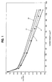
- Figures 1 and 2 were produced from data measured from four electrochemical fuel cells which used 20% Pt/Shawinigan electrocatalyst particles.
- the four electrochemical fuel cells were all made in substantially the same way except for the treatment of the electrocatalyst particles.
- Three of the electrochemical fuel cells used electrocatalyst particles which were vacuum impregnated with an impregnant.
- a different impregnant was used for each one of the three electrochemical fuel cells, namely perfluorotributylamine, H 3 PO 4 , and Nafion.
- the fourth electrochemical fuel cell used electrocatalyst particles which were not vacuum impregnated, but which were deposited on the electrode substrate in a Nafion ink.
- FIG. 1 is a plot of cell voltage versus current density for the four electrochemical fuel cells.
- Plot A1 is a plot of the performance measured for an electrochemical fuel cell using electrocatalyst particles which were not vacuum impregnated.
- Plot A1 represents the performance achieved by a prior art electrochemical fuel cell using untreated 20%/Shawinigan electrocatalyst particles deposited in a Nafion ink solution.
- Figure 1 shows that an improvement in electrochemical fuel cell performance can be attained by using vacuum impregnated electrocatalysts.
- the electrocatalyst particles were pre-treated prior to deposition on to an electrode support.
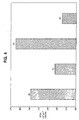
- Figure 2 is a chart which shows the EPSA for the four electrochemical fuel cells.
- Bar A2 represents the EPSA for the conventional untreated electrocatalyst particles.
- Bar B2 represents the EPSA for the electrocatalyst particles which were vacuum impregnated with perfluorotributylamine.
- Bar C2 represents the EPSA for the electrocatalyst particles which were vacuum impregnated with H 3 PO 4 .
- Bar D2 represents the EPSA for the electrocatalyst particles which were vacuum impregnated with Nafion.
- Figure 2 shows that all of the electrocatalyst particles which were vacuum impregnated with an impregnant yielded higher EPSAs compared to the untreated electrocatalyst particles which had an EPSA of 175 cm 2 /cm 2 (Bar A2).
- Figures 3 and 4 were produced from data measured from four electrochemical fuel cells which used 40% Pt/XC72R clectrocatalyst particles.
- the four electrochemical fuel cells were all made in substantially the same way except for the treatment of the electrocatalyst particles.
- Three of the electrochemical fuel cells used electrocatalyst particles which were vacuum impregnated with an impregnant.
- a different impregnant was used for each one of the three electrochemical fuel cells, namely H 3 PO 4 , Nafion, and perfluorotributylamine.
- the fourth electrochemical fuel cell used electrocatalyst particles which were not vacuum impregnated, but which were deposited on the electrode substrate in a Nafion ink.
- Figure 3 is a plot of cell voltage versus current density for the four electrochemical fuel cells which used 40% Pt/XC72R electrocatalyst particles.
- Plot E1 represents the performance achieved by a prior art electrochemical fuel cell using untreated 40% Pt/XC72R electrocatalyst particles deposited in a Nafion ink solution.
- Plot F 1 is a plot of the performance measured for an electrochemical fuel cell using electrocatalyst particles which were vacuum impregnated with perfluorotributylamine.
- Plot G1 is a plot of the performance measured for an electrochemical fuel cell using electrocatalyst particles which were vacuum impregnated with H 3 PO 4 .
- Plot H1 is a plot of the performance measured for an electrochemical fuel cell using electrocatalyst particles which were vacuum impregnated with Nafion.
- the polarization curves in Figure 3 show that the effect of the vacuum impregnation treatment of the 40% Pt/XC72R electrocatalyst particles produced a smaller improvement in fuel cell performance compared to the treated 20% Pt/Shawinigan electrocatalyst particles.
- the performance of the electrochemical fuel cell which used electrocatalyst particles impregnated with perfluorotributylamine was essentially the same as the electrochemical fuel cell which used untreated electrocatalyst particles.
- the electrochemical fuel cells which used H 3 PO 4 and Nafion as the impregnants performed only slightly better than the electrochemical fuel cell which used untreated electrocatalyst.
- the electrochemical fuel cell using H 3 PO 4 as the impregnant yielded the best results.
- Figure 4 is a chart which shows the EPSA for the four electrochemical fuel cells which used 40% Pt/XC72R electrocatalyst particles.
- Bar E2 represents the EPSA for the untreated electrocatalyst particles.
- Bar F2 represents the EPSA for the electrocatalyst particles which were vacuum impregnated with perfluorotributylamine.
- Bar G2 represents the EPSA for the electrocatalyst particles which were vacuum impregnated with H 3 PO 4 .
- Bar H2 represents the EPSA for the electrocatalyst particles which were vacuum impregnated with Nafion.
- the EPSA data for the 40% Pt/XC72R electrocatalyst particles is less conclusive than the EPSA data for the 20% Pt/Shawinigan electrocatalyst particles.
- Figures 3 and 4 shows that the 40% Pt/XC72R electrocatalyst particles which were impregnated with H 3 PO 4 had the highest EPSA and yielded the highest performance.
- Examples 1 and 2 show that improved performance may be achieved by using a vacuum impregnated electrocatalyst in an operating electrochemical fuel cell.
- a general observation from the results obtained using H 3 PO 4 and Nafion as impregnants is that the impregnant with the smaller molecular weight yielded better results when used to impregnate either the 20% Pt/Shawinigan or the 40% Pt/XC72R electrocatalyst.
- the solubility of air in water is 1.9ml/l 00ml whereas, at the same temperature, the solubility of air in perfluorotributlyamine is 27.
- Perfluorotributylamine is not an ionically conductive, so the results from the tests using 20% Pt/Shawinigan electrocatalyst particles impregnated with perfluorotributylamine demonstrate that improving oxygen permeability within the electrocatalyst micropores is an important factor in improving electrochemical fuel cell performance.
Landscapes
- Chemical & Material Sciences (AREA)
- Chemical Kinetics & Catalysis (AREA)
- Electrochemistry (AREA)
- General Chemical & Material Sciences (AREA)
- Engineering & Computer Science (AREA)
- Materials Engineering (AREA)
- Manufacturing & Machinery (AREA)
- Life Sciences & Earth Sciences (AREA)
- Sustainable Development (AREA)
- Sustainable Energy (AREA)
- Fuel Cell (AREA)
- Inert Electrodes (AREA)
- Electrolytic Production Of Non-Metals, Compounds, Apparatuses Therefor (AREA)
Abstract
Description
| Fuel | hydrogen |
| Fuel pressure | 30 psig |
| Fuel stoichiometry | 1.5 |
| Oxidant | oxygen |
| Oxidant pressure | 30 psig |
| Oxidant stoichiometry | 2.0 |
| Fuel cell temperature | 80°C |
Claims (22)
- A method of improving electrochemical fuel cell performance, the method comprising incorporating porous electrocatalyst particles in said electrochemical fuel cell at an interface between an electrode and an electrolyte, wherein pores in said particles have been impregnated with an impregnant by:preparing a liquid mixture comprising said porous electrocatalyst particles and an excess of said impregnant;treating said mixture to vacuum, wherein the vacuum is sufficient to facilitate penetration of the impregnant into the pores; andremoving liquid and said excess of said impregnant from said mixture after said vacuum treatment.
- The method of claim 1 wherein said pores in said particles have an aperture size less than 0.1 micron.
- The method of claim 1 further comprising the step of treating said mixture to a pressure above atmospheric pressure.
- The method of claim 1 wherein said impregnant comprises an ion-conducting material.
- The method of claim 1 wherein said impregnant comprises a material with oxygen permeability greater than that of water.
- The method of claim 1 wherein said electrocatalyst is a carbon-supported electrocatalyst.
- The method of claim 1 wherein said removing comprises filtering or decanting.
- The method of claim 1 wherein liquid is further removed by drying in an oven.
- The method of claim 1 wherein said impregnant improves access to interior electrocatalyst surface areas within said micropores by improving mass transport properties within said micropores for a reactant or a product of an electrochemical reaction induced by said electrocatalyst.
- The method of claim 4 wherein said ion-conducting material is an inorganic acid.
- The method of claim 10 wherein said inorganic acid is selected from the group consisting of H3PO4 and HNO3.
- The method of claim 4 wherein said ion-conducting material is an organic acid.
- The method of claim 12 wherein said organic acid is a fluorinated organic acid.
- The method of claim 12 wherein said organic acid is selected from the group consisting of CF3COOH, and CF3SO3H.
- The method of claim 4 wherein said ion-conducting material is a polymer.
- The method of claim 5 wherein said material with oxygen permeability greater than that of water is an organic fluid.
- The method of claim 16 wherein said organic fluid is selected from the group consisting of hydrocarbons, fluorocarbons, and non-halogenated oils.
- The method of claim 16 wherein said organic fluid is a perfluorocarbon.
- The method of claim 18 wherein said perfluorocarbon is selected from the group consisting of perfluorotripropylamine cis-perfluorodecalin, trans-perfluorodecalin, perfluoro-1-methyl decalin, perfluoroisopentyltetrahydropyrane, perfluoro-N,N-dimethylcyclohexylamine, perfluoroperhydrophenanthrene, and perfluorotributylamine.
- The method of claim 17 wherein said organic fluid is a silicone oil or a mineral oil.
- The method of claim 1 wherein said impregnant is hydrophobic.
- The method of claim 1 wherein said electrolyte is an ion exchange membrane.
Applications Claiming Priority (3)
| Application Number | Priority Date | Filing Date | Title |
|---|---|---|---|
| US36389 | 1998-03-06 | ||
| US09/036,389 US6074773A (en) | 1998-03-06 | 1998-03-06 | Impregnation of microporous electrocatalyst particles for improving performance in an electrochemical fuel cell |
| PCT/CA1999/000181 WO1999045606A1 (en) | 1998-03-06 | 1999-03-04 | Impregnation of microporous electrocatalyst particles for improving performance in an electrochemical fuel cell |
Publications (2)
| Publication Number | Publication Date |
|---|---|
| EP1068649A1 EP1068649A1 (en) | 2001-01-17 |
| EP1068649B1 true EP1068649B1 (en) | 2004-05-26 |
Family
ID=21888348
Family Applications (1)
| Application Number | Title | Priority Date | Filing Date |
|---|---|---|---|
| EP99938016A Expired - Lifetime EP1068649B1 (en) | 1998-03-06 | 1999-03-04 | Impregnation of microporous electrocatalyst particles for improving performance in an electrochemical fuel cell |
Country Status (7)
| Country | Link |
|---|---|
| US (2) | US6074773A (en) |
| EP (1) | EP1068649B1 (en) |
| AT (1) | ATE268061T1 (en) |
| AU (1) | AU3242999A (en) |
| CA (1) | CA2322692A1 (en) |
| DE (1) | DE69917622D1 (en) |
| WO (1) | WO1999045606A1 (en) |
Cited By (1)
| Publication number | Priority date | Publication date | Assignee | Title |
|---|---|---|---|---|
| EP4218069A4 (en) * | 2020-09-28 | 2025-08-06 | Hyzon Motors Usa Inc | Membrane electrode assembly with improved performance using two-component fluorinated mixed electrolyte additives |
Families Citing this family (42)
| Publication number | Priority date | Publication date | Assignee | Title |
|---|---|---|---|---|
| US6548202B2 (en) | 1998-03-06 | 2003-04-15 | Ballard Power System, Inc. | Carbon-supported catalysts for fuel cells |
| US6153323A (en) * | 1998-10-16 | 2000-11-28 | Ballard Power Systems Inc. | Electrode treatment method for improving performance in liquid feed fuel cells |
| DE10001170A1 (en) * | 1999-01-13 | 2000-07-27 | Japan Storage Battery Co Ltd | Gas diffusion electrode comprises a gas diffusion layer and a catalyst layer a porous electrolyte and microporous catalyst-electrolyte aggregate |
| US6517962B1 (en) * | 1999-08-23 | 2003-02-11 | Ballard Power Systems Inc. | Fuel cell anode structures for voltage reversal tolerance |
| EP1232533A2 (en) | 1999-11-17 | 2002-08-21 | Neah Power Systems, Inc. | Fuel cells having silicon substrates and/or sol-gel derived support structures |
| US6740445B1 (en) | 2000-02-29 | 2004-05-25 | Ion Power, Inc. | Coated fuel cell electrodes |
| ATE478913T1 (en) * | 2000-06-02 | 2010-09-15 | Stanford Res Inst Int | POLYMER MEMBRANE COMPOSITION |
| CA2356008C (en) * | 2000-09-01 | 2010-01-05 | Honda Giken Kogyo Kabushiki Kaisha | Membrane electrode assembly for fuel cell and method for producing the same |
| US6696382B1 (en) * | 2000-11-14 | 2004-02-24 | The Regents Of The University Of California | Catalyst inks and method of application for direct methanol fuel cells |
| US6630263B1 (en) | 2000-11-20 | 2003-10-07 | Plug Power Inc. | Fuel cell systems and methods |
| EP2009720B1 (en) * | 2001-01-19 | 2010-12-29 | Panasonic Corporation | Electrolyte membrane-electrode assembly for fuel cell |
| US7316855B2 (en) | 2001-06-01 | 2008-01-08 | Polyfuel, Inc. | Fuel cell assembly for portable electronic device and interface, control, and regulator circuit for fuel cell powered electronic device |
| WO2002099916A2 (en) | 2001-06-01 | 2002-12-12 | Polyfuel, Inc | Fuel cell assembly for portable electronic device and interface, control, and regulator circuit for fuel cell powered electronic device |
| WO2003096462A1 (en) * | 2002-05-09 | 2003-11-20 | Anuvu, Inc. , A California Corporation | Electrochemical fuel cell comprised of a series of conductive compression gaskets and method of manufacture |
| US7037319B2 (en) * | 2002-10-15 | 2006-05-02 | Scimed Life Systems, Inc. | Nanotube paper-based medical device |
| CA2508123A1 (en) * | 2002-12-02 | 2004-06-17 | Polyfuel, Inc. | Fuel cell cartridge for portable electronic device |
| US7722981B2 (en) * | 2006-09-11 | 2010-05-25 | Nanotek Instruments, Inc. | Electro-catalyst composition, fuel cell electrode, and membrane-electrode assembly |
| US8318385B2 (en) * | 2006-09-19 | 2012-11-27 | Nanotek Instruments, Inc. | Process for producing fuel cell electrode |
| US8202669B2 (en) * | 2006-10-19 | 2012-06-19 | Nanotek Instruments, Inc. | Electro-catalyst compositions for fuel cells |
| US20080182153A1 (en) * | 2007-01-30 | 2008-07-31 | Jang Bor Z | Fuel cell electro-catalyst composite composition, electrode, catalyst-coated membrane, and membrane-electrode assembly |
| US9318762B2 (en) * | 2007-02-12 | 2016-04-19 | Nanotek Instruments, Inc. | Conducting polymer-transition metal electro-catalyst compositions for fuel cells |
| US7785498B2 (en) * | 2007-07-19 | 2010-08-31 | Nanotek Instruments, Inc. | Method of producing conducting polymer-transition metal electro-catalyst composition and electrodes for fuel cells |
| KR101080783B1 (en) * | 2008-10-06 | 2011-11-07 | 현대자동차주식회사 | Process for maufacturing electrode and Membrane-Electrode Assembly for Polymer Electrolyte Membrane Fuel Cell |
| US8735017B2 (en) * | 2010-03-10 | 2014-05-27 | Samsung Sdi Co., Ltd | Membrane-electrode assembly for fuel cell, method of manufacturing membrane-electrode assembly for fuel cell, and fuel cell system |
| US9742008B2 (en) | 2013-12-03 | 2017-08-22 | Ionic Materials, Inc. | Solid, ionically conducting polymer material, and methods and applications for same |
| US11251455B2 (en) | 2012-04-11 | 2022-02-15 | Ionic Materials, Inc. | Solid ionically conducting polymer material |
| US10199657B2 (en) | 2012-04-11 | 2019-02-05 | Ionic Materials, Inc. | Alkaline metal-air battery cathode |
| US11152657B2 (en) | 2012-04-11 | 2021-10-19 | Ionic Materials, Inc. | Alkaline metal-air battery cathode |
| US12074274B2 (en) | 2012-04-11 | 2024-08-27 | Ionic Materials, Inc. | Solid state bipolar battery |
| US9819053B1 (en) | 2012-04-11 | 2017-11-14 | Ionic Materials, Inc. | Solid electrolyte high energy battery |
| US10559827B2 (en) | 2013-12-03 | 2020-02-11 | Ionic Materials, Inc. | Electrochemical cell having solid ionically conducting polymer material |
| US8906572B2 (en) * | 2012-11-30 | 2014-12-09 | General Electric Company | Polymer-electrolyte membrane, electrochemical fuel cell, and related method |
| HUE053572T2 (en) | 2014-04-01 | 2021-07-28 | Ionic Mat Inc | High capacity polymer cathode and high energy density rechargeable cell containing the cathode |
| KR102654722B1 (en) * | 2015-06-02 | 2024-04-03 | 아이오닉 머터리얼스, 인코퍼레이션 | Cathode of Alkali Metal-Air Battery |
| EP3304620A4 (en) | 2015-06-04 | 2018-11-07 | Ionic Materials, Inc. | Solid state bipolar battery |
| KR102640010B1 (en) | 2015-06-04 | 2024-02-22 | 아이오닉 머터리얼스, 인코퍼레이션 | Lithium metal battery with solid polymer electrolyte |
| US11342559B2 (en) | 2015-06-08 | 2022-05-24 | Ionic Materials, Inc. | Battery with polyvalent metal anode |
| KR102607433B1 (en) | 2015-06-08 | 2023-11-27 | 아이오닉 머터리얼스, 인코퍼레이션 | Battery with aluminum anode and solid polymer |
| CN110337746A (en) | 2017-01-26 | 2019-10-15 | 离子材料公司 | Alkaline cell cathode with solid polymer electrolyte |
| DE102017204096A1 (en) * | 2017-03-13 | 2018-09-13 | Siemens Aktiengesellschaft | Production of gas diffusion electrodes with ion transport resins for the electrochemical reduction of CO2 to chemical recyclables |
| KR20210072986A (en) * | 2019-12-10 | 2021-06-18 | 현대자동차주식회사 | Manufacturing method of catalyst slurry for fuel cell and manufacturing method of electrode for fuel cell by using the catalyst slurry |
| CN116598485A (en) * | 2023-04-17 | 2023-08-15 | 孚能科技(赣州)股份有限公司 | Composite negative electrode material and preparation method thereof, sodium ion battery |
Family Cites Families (16)
| Publication number | Priority date | Publication date | Assignee | Title |
|---|---|---|---|---|
| US3769093A (en) * | 1970-08-21 | 1973-10-30 | Gen Electric | Vacuum loading process for the manufacture of a narrow pore fluid electrode |
| DE2713317A1 (en) * | 1977-03-25 | 1978-09-28 | Licentia Gmbh | METHOD FOR PRODUCING AN ELECTRODE FOR FUEL CELL BATTERIES |
| FR2404312A1 (en) * | 1977-09-27 | 1979-04-20 | Anvar | Gas electrode for fuel cell - has a current-conducting element with a catalytic layer and a gas-permeable but electrolyte-impermeable layer |
| JPS5983352A (en) * | 1982-11-05 | 1984-05-14 | Nissan Motor Co Ltd | Manufacture of electrode for fuel cell |
| JPS6167789A (en) * | 1984-09-10 | 1986-04-07 | Japan Storage Battery Co Ltd | Production of joined body of ion exchange resin film and electrode |
| EP0305565B1 (en) * | 1987-08-19 | 1993-02-24 | The Dow Chemical Company | Current collector bonded to a solid polymer membrane |
| JPH04162365A (en) * | 1990-10-25 | 1992-06-05 | Tanaka Kikinzoku Kogyo Kk | Method for preparing electrode of fuel cell |
| US5185218A (en) * | 1990-12-31 | 1993-02-09 | Luz Electric Fuel Israel Ltd | Electrodes for metal/air batteries and fuel cells and metal/air batteries incorporating the same |
| DK167946B1 (en) * | 1991-06-28 | 1994-01-03 | Topsoe Haldor As | PHOSPHORIC ACID COMBUSTION CELL WITH IMPROVED ELECTRIC EFFICIENCY |
| JPH05144444A (en) * | 1991-11-25 | 1993-06-11 | Toshiba Corp | Fuel cell and electrode manufacturing method |
| GB9213124D0 (en) * | 1992-06-20 | 1992-08-05 | Johnson Matthey Plc | High performance electrode |
| JPH07176310A (en) * | 1993-12-20 | 1995-07-14 | Sanyo Electric Co Ltd | Electrode and junction body between electrode and ion exchange membrane |
| DE69435082T2 (en) * | 1994-10-18 | 2008-08-14 | The University Of Southern California, Los Angeles | ORGANIC FUEL CELL, METHOD OF OPERATING THE CELL AND PRODUCING AN ELECTRODE THEREFOR |
| JPH08227716A (en) * | 1995-02-22 | 1996-09-03 | Tanaka Kikinzoku Kogyo Kk | Raw material for electrode of polymer solid oxide fuel cell and method for producing the same |
| JP3584612B2 (en) * | 1996-05-30 | 2004-11-04 | 旭硝子株式会社 | Polymer electrolyte fuel cell and method for manufacturing electrode thereof |
| US6306536B1 (en) * | 1998-03-27 | 2001-10-23 | Ballard Power Systems Inc. | Method of reducing fuel cell performance degradation of an electrode comprising porous components |
-
1998
- 1998-03-06 US US09/036,389 patent/US6074773A/en not_active Expired - Lifetime
-
1999
- 1999-03-04 WO PCT/CA1999/000181 patent/WO1999045606A1/en not_active Ceased
- 1999-03-04 AT AT99938016T patent/ATE268061T1/en not_active IP Right Cessation
- 1999-03-04 US US09/623,254 patent/US6610432B1/en not_active Expired - Fee Related
- 1999-03-04 CA CA002322692A patent/CA2322692A1/en not_active Abandoned
- 1999-03-04 EP EP99938016A patent/EP1068649B1/en not_active Expired - Lifetime
- 1999-03-04 DE DE69917622T patent/DE69917622D1/en not_active Expired - Lifetime
- 1999-03-04 AU AU32429/99A patent/AU3242999A/en not_active Abandoned
Cited By (1)
| Publication number | Priority date | Publication date | Assignee | Title |
|---|---|---|---|---|
| EP4218069A4 (en) * | 2020-09-28 | 2025-08-06 | Hyzon Motors Usa Inc | Membrane electrode assembly with improved performance using two-component fluorinated mixed electrolyte additives |
Also Published As
| Publication number | Publication date |
|---|---|
| CA2322692A1 (en) | 1999-09-10 |
| ATE268061T1 (en) | 2004-06-15 |
| AU3242999A (en) | 1999-09-20 |
| EP1068649A1 (en) | 2001-01-17 |
| WO1999045606A1 (en) | 1999-09-10 |
| US6610432B1 (en) | 2003-08-26 |
| US6074773A (en) | 2000-06-13 |
| DE69917622D1 (en) | 2004-07-01 |
Similar Documents
| Publication | Publication Date | Title |
|---|---|---|
| EP1068649B1 (en) | Impregnation of microporous electrocatalyst particles for improving performance in an electrochemical fuel cell | |
| US5922488A (en) | Co-tolerant fuel cell electrode | |
| US6153323A (en) | Electrode treatment method for improving performance in liquid feed fuel cells | |
| Hagihara et al. | Preparation of highly dispersed SiO2 and Pt particles in NafionŪ112 for self-humidifying electrolyte membranes in fuel cells | |
| EP1045467B1 (en) | Layered carbon electrode for electrochemical cells | |
| EP0603175B1 (en) | High utilization supported catalytic metal-containing gas-diffusion electrode, process for making it, and cells utilizing it | |
| EP0920065B1 (en) | Solid polymer electrolyte-catalyst composite electrode, electrode for fuel cell, and process for producing these electrodes | |
| Aricò et al. | Ac-impedance spectroscopy study of oxygen reduction at Nafion® coated gas-diffusion electrodes in sulphuric acid: Teflon loading and methanol cross-over effects | |
| Waldrop et al. | Electrospun nanofiber electrodes for high and low humidity PEMFC operation | |
| EP1133805B1 (en) | Ionomer impregnation of electrode substrates for improved fuel cell performance | |
| WO2023112958A1 (en) | Ionic liquid-impregnated inorganic material-coated catalyst particles, membrane electrode assembly for fuel cells, and fuel cell | |
| WO2004019435A2 (en) | Conductive carbon, electrode catalyst for fuel cell using the same and fuel cell | |
| US6306536B1 (en) | Method of reducing fuel cell performance degradation of an electrode comprising porous components | |
| Kim et al. | A facile approach to improve the performance of alkaline anion exchange membrane fuel cells by reducing ionic resistance | |
| US7220693B1 (en) | Fuel cell catalyst electrodes | |
| KR102299218B1 (en) | Ionomer-ionomer support composite, method for preparing the same, and catalyst electrode for fuel cell comprising the ionomer-ionomer support composite | |
| CN117500593A (en) | Ionic liquid impregnated catalyst particles, membrane electrode assembly for fuel cells, and fuel cells | |
| EP4179584B1 (en) | Catalyst preparation | |
| Moreira et al. | Dependence of PEM fuel cell performance on the configuration of the gas diffusion electrodes | |
| Aric et al. | Ac-impedance spectroscopy study of oxygen reduction at Nafion� coated gas-diffusion electrodes in sulphuric acid: Teflon loading and methanol cross-over effects | |
| Chang et al. | Process and Characteristics of High Power Catalyst Electrode for PEM Fuel Cell | |
| KR20020032021A (en) | Membrane electrode assembly for fuel cell operable in non-humidified fuel condition |
Legal Events
| Date | Code | Title | Description |
|---|---|---|---|
| PUAI | Public reference made under article 153(3) epc to a published international application that has entered the european phase |
Free format text: ORIGINAL CODE: 0009012 |
|
| 17P | Request for examination filed |
Effective date: 20000928 |
|
| AK | Designated contracting states |
Kind code of ref document: A1 Designated state(s): AT BE CH CY DE DK ES FI FR GB GR IE IT LI LU MC NL PT SE |
|
| 17Q | First examination report despatched |
Effective date: 20010320 |
|
| GRAP | Despatch of communication of intention to grant a patent |
Free format text: ORIGINAL CODE: EPIDOSNIGR1 |
|
| GRAS | Grant fee paid |
Free format text: ORIGINAL CODE: EPIDOSNIGR3 |
|
| GRAA | (expected) grant |
Free format text: ORIGINAL CODE: 0009210 |
|
| AK | Designated contracting states |
Kind code of ref document: B1 Designated state(s): AT BE CH CY DE DK ES FI FR GB GR IE IT LI LU MC NL PT SE |
|
| PG25 | Lapsed in a contracting state [announced via postgrant information from national office to epo] |
Ref country code: NL Free format text: LAPSE BECAUSE OF FAILURE TO SUBMIT A TRANSLATION OF THE DESCRIPTION OR TO PAY THE FEE WITHIN THE PRESCRIBED TIME-LIMIT Effective date: 20040526 Ref country code: LI Free format text: LAPSE BECAUSE OF FAILURE TO SUBMIT A TRANSLATION OF THE DESCRIPTION OR TO PAY THE FEE WITHIN THE PRESCRIBED TIME-LIMIT Effective date: 20040526 Ref country code: IT Free format text: LAPSE BECAUSE OF FAILURE TO SUBMIT A TRANSLATION OF THE DESCRIPTION OR TO PAY THE FEE WITHIN THE PRESCRIBED TIME-LIMIT;WARNING: LAPSES OF ITALIAN PATENTS WITH EFFECTIVE DATE BEFORE 2007 MAY HAVE OCCURRED AT ANY TIME BEFORE 2007. THE CORRECT EFFECTIVE DATE MAY BE DIFFERENT FROM THE ONE RECORDED. Effective date: 20040526 Ref country code: FR Free format text: LAPSE BECAUSE OF NON-PAYMENT OF DUE FEES Effective date: 20040526 Ref country code: FI Free format text: LAPSE BECAUSE OF FAILURE TO SUBMIT A TRANSLATION OF THE DESCRIPTION OR TO PAY THE FEE WITHIN THE PRESCRIBED TIME-LIMIT Effective date: 20040526 Ref country code: CH Free format text: LAPSE BECAUSE OF FAILURE TO SUBMIT A TRANSLATION OF THE DESCRIPTION OR TO PAY THE FEE WITHIN THE PRESCRIBED TIME-LIMIT Effective date: 20040526 Ref country code: BE Free format text: LAPSE BECAUSE OF FAILURE TO SUBMIT A TRANSLATION OF THE DESCRIPTION OR TO PAY THE FEE WITHIN THE PRESCRIBED TIME-LIMIT Effective date: 20040526 Ref country code: AT Free format text: LAPSE BECAUSE OF FAILURE TO SUBMIT A TRANSLATION OF THE DESCRIPTION OR TO PAY THE FEE WITHIN THE PRESCRIBED TIME-LIMIT Effective date: 20040526 |
|
| REG | Reference to a national code |
Ref country code: GB Ref legal event code: FG4D |
|
| REG | Reference to a national code |
Ref country code: CH Ref legal event code: EP |
|
| REG | Reference to a national code |
Ref country code: IE Ref legal event code: FG4D |
|
| REF | Corresponds to: |
Ref document number: 69917622 Country of ref document: DE Date of ref document: 20040701 Kind code of ref document: P |
|
| PG25 | Lapsed in a contracting state [announced via postgrant information from national office to epo] |
Ref country code: SE Free format text: LAPSE BECAUSE OF FAILURE TO SUBMIT A TRANSLATION OF THE DESCRIPTION OR TO PAY THE FEE WITHIN THE PRESCRIBED TIME-LIMIT Effective date: 20040826 Ref country code: GR Free format text: LAPSE BECAUSE OF FAILURE TO SUBMIT A TRANSLATION OF THE DESCRIPTION OR TO PAY THE FEE WITHIN THE PRESCRIBED TIME-LIMIT Effective date: 20040826 Ref country code: DK Free format text: LAPSE BECAUSE OF FAILURE TO SUBMIT A TRANSLATION OF THE DESCRIPTION OR TO PAY THE FEE WITHIN THE PRESCRIBED TIME-LIMIT Effective date: 20040826 |
|
| PG25 | Lapsed in a contracting state [announced via postgrant information from national office to epo] |
Ref country code: DE Free format text: LAPSE BECAUSE OF FAILURE TO SUBMIT A TRANSLATION OF THE DESCRIPTION OR TO PAY THE FEE WITHIN THE PRESCRIBED TIME-LIMIT Effective date: 20040827 |
|
| PG25 | Lapsed in a contracting state [announced via postgrant information from national office to epo] |
Ref country code: ES Free format text: LAPSE BECAUSE OF FAILURE TO SUBMIT A TRANSLATION OF THE DESCRIPTION OR TO PAY THE FEE WITHIN THE PRESCRIBED TIME-LIMIT Effective date: 20040906 |
|
| REG | Reference to a national code |
Ref country code: CH Ref legal event code: PL |
|
| NLV1 | Nl: lapsed or annulled due to failure to fulfill the requirements of art. 29p and 29m of the patents act | ||
| PG25 | Lapsed in a contracting state [announced via postgrant information from national office to epo] |
Ref country code: LU Free format text: LAPSE BECAUSE OF NON-PAYMENT OF DUE FEES Effective date: 20050304 Ref country code: IE Free format text: LAPSE BECAUSE OF NON-PAYMENT OF DUE FEES Effective date: 20050304 Ref country code: GB Free format text: LAPSE BECAUSE OF NON-PAYMENT OF DUE FEES Effective date: 20050304 Ref country code: CY Free format text: LAPSE BECAUSE OF FAILURE TO SUBMIT A TRANSLATION OF THE DESCRIPTION OR TO PAY THE FEE WITHIN THE PRESCRIBED TIME-LIMIT Effective date: 20050304 |
|
| PG25 | Lapsed in a contracting state [announced via postgrant information from national office to epo] |
Ref country code: MC Free format text: LAPSE BECAUSE OF NON-PAYMENT OF DUE FEES Effective date: 20050331 |
|
| PLBE | No opposition filed within time limit |
Free format text: ORIGINAL CODE: 0009261 |
|
| STAA | Information on the status of an ep patent application or granted ep patent |
Free format text: STATUS: NO OPPOSITION FILED WITHIN TIME LIMIT |
|
| 26N | No opposition filed |
Effective date: 20050301 |
|
| EN | Fr: translation not filed | ||
| GBPC | Gb: european patent ceased through non-payment of renewal fee |
Effective date: 20050304 |
|
| REG | Reference to a national code |
Ref country code: IE Ref legal event code: MM4A |
|
| PG25 | Lapsed in a contracting state [announced via postgrant information from national office to epo] |
Ref country code: PT Free format text: LAPSE BECAUSE OF NON-PAYMENT OF DUE FEES Effective date: 20041026 |