EP1068508B1 - Vorrichtung zur untersuchung von reibverhältnissen - Google Patents
Vorrichtung zur untersuchung von reibverhältnissen Download PDFInfo
- Publication number
- EP1068508B1 EP1068508B1 EP99922083A EP99922083A EP1068508B1 EP 1068508 B1 EP1068508 B1 EP 1068508B1 EP 99922083 A EP99922083 A EP 99922083A EP 99922083 A EP99922083 A EP 99922083A EP 1068508 B1 EP1068508 B1 EP 1068508B1
- Authority
- EP
- European Patent Office
- Prior art keywords
- force
- application
- normal force
- force sensor
- friction
- Prior art date
- Legal status (The legal status is an assumption and is not a legal conclusion. Google has not performed a legal analysis and makes no representation as to the accuracy of the status listed.)
- Expired - Lifetime
Links
- 238000005452 bending Methods 0.000 claims description 12
- 230000003287 optical effect Effects 0.000 claims description 7
- 230000008878 coupling Effects 0.000 claims description 6
- 238000010168 coupling process Methods 0.000 claims description 6
- 238000005859 coupling reaction Methods 0.000 claims description 6
- 239000011521 glass Substances 0.000 claims description 6
- 238000012545 processing Methods 0.000 claims description 4
- 239000000835 fiber Substances 0.000 claims description 3
- 238000005516 engineering process Methods 0.000 claims description 2
- 238000005530 etching Methods 0.000 claims 1
- 238000006073 displacement reaction Methods 0.000 description 4
- 238000011835 investigation Methods 0.000 description 4
- 230000005540 biological transmission Effects 0.000 description 3
- 238000010586 diagram Methods 0.000 description 3
- 238000005259 measurement Methods 0.000 description 3
- 238000013461 design Methods 0.000 description 2
- 238000004519 manufacturing process Methods 0.000 description 2
- 239000000463 material Substances 0.000 description 2
- 230000005855 radiation Effects 0.000 description 2
- 238000012360 testing method Methods 0.000 description 2
- 238000010276 construction Methods 0.000 description 1
- 230000001419 dependent effect Effects 0.000 description 1
- 229920001903 high density polyethylene Polymers 0.000 description 1
- 239000004700 high-density polyethylene Substances 0.000 description 1
- 238000002347 injection Methods 0.000 description 1
- 239000007924 injection Substances 0.000 description 1
- 230000003993 interaction Effects 0.000 description 1
- 239000002184 metal Substances 0.000 description 1
- 239000013307 optical fiber Substances 0.000 description 1
- WXZMFSXDPGVJKK-UHFFFAOYSA-N pentaerythritol Chemical compound OCC(CO)(CO)CO WXZMFSXDPGVJKK-UHFFFAOYSA-N 0.000 description 1
- 239000005020 polyethylene terephthalate Substances 0.000 description 1
- 229920000139 polyethylene terephthalate Polymers 0.000 description 1
- 239000004810 polytetrafluoroethylene Substances 0.000 description 1
- 229920001343 polytetrafluoroethylene Polymers 0.000 description 1
- 230000035945 sensitivity Effects 0.000 description 1
- 239000007858 starting material Substances 0.000 description 1
- 230000001629 suppression Effects 0.000 description 1
- 238000005211 surface analysis Methods 0.000 description 1
Images


Classifications
-
- G—PHYSICS
- G01—MEASURING; TESTING
- G01N—INVESTIGATING OR ANALYSING MATERIALS BY DETERMINING THEIR CHEMICAL OR PHYSICAL PROPERTIES
- G01N19/00—Investigating materials by mechanical methods
- G01N19/02—Measuring coefficient of friction between materials
-
- G—PHYSICS
- G01—MEASURING; TESTING
- G01N—INVESTIGATING OR ANALYSING MATERIALS BY DETERMINING THEIR CHEMICAL OR PHYSICAL PROPERTIES
- G01N2203/00—Investigating strength properties of solid materials by application of mechanical stress
- G01N2203/02—Details not specific for a particular testing method
- G01N2203/06—Indicating or recording means; Sensing means
- G01N2203/0617—Electrical or magnetic indicating, recording or sensing means
- G01N2203/0623—Electrical or magnetic indicating, recording or sensing means using piezoelectric gauges
Definitions
- the invention relates to a device for examining friction conditions on friction partners with which a normal force between two examining Frictional partner stamped and with a normal force sensor is determined and in the case of a relative movement between the Tangential force acting on the friction partners is determined with a friction force sensor becomes.
- the device is used to determine small friction values with high accuracy.
- Various designs for devices for the precise investigation of frictional conditions are known in the prior art.
- Mittmann, Czichos: friction measurements and surface investigations on plastic-metal sliding partners; Material edition 17, 1975, No. 10, Oct., p.366, 367 describes a device which is designed as a pin-disk triborneter.
- the tests are carried out in a closed, temperature-controlled test chamber that can be flushed with a defined gas.
- the disc drives a tachometer-controlled DC motor via an intermediate gear at a constant speed.
- a cylindrical pin made of PTFE, HDPE or PETP is cut with a microtome before the examination.
- the pen is aligned parallel to the surface of the pane using an observation telescope.
- An arrangement of four bending beams is used as the force transducer.
- a disadvantage of the known arrangements is that they are either one require complex construction or only a low measuring accuracy enable.
- the invention is based on the object of a device at the outset Specify the type mentioned, a measurement with high Accuracy and good reproducibility enabled.
- the device has an elastic bending element made of glass, which contains several spring arrangements with different spring stiffness.
- a soft parallel spring element with stops for impressing the tangential movement and a harder leaf spring element for normal force injection, which acts perpendicular to the two parallel spring elements, are integrated in the elastic element.
- the force introduction points and the sensors are each located on opposite parts of the elastic bending element.
- the front-wheel drive expediently an adjusting device for parallel alignment of the integrated on both body levels.
- the normal force is with a force sensor, preferably by means of an optical displacement sensor, into an electrical signal converted.
- the tangential acting friction force can be determined. For this purpose, a relative movement with impressed on the tangential drive.
- the soft, elastic tangential guide and the associated force attack follow depending on the Frictional conditions of the driving force are not direct, but it results a path difference between the part connected to the force attack the elastic tangential guide and the one with the tangential drive connected part of the tangential guide.
- This path difference is in Dependence on the impressed normal force and on the elastic Properties of the tangential guide a measure of those to be determined Friction conditions.
- the path difference is measured with the help of a sensor, preferably with an optical displacement sensor, into an electrical signal converted and together with the signal from the normal force sensor Signal processing unit supplied.
- FIG. 1 shows the individual functional elements the measuring arrangement and their interaction.
- FIG. 2 explains the operation of the measuring arrangement.
- the friction partners come into contact with the force application surface 1 and the force transmission surface 2.
- a normal force is impressed between the friction partners.
- a frontal movement running in the horizontal direction is generated by means of the frontal drive.
- An adjustment device is integrated in the frontal drive 5, which allows a parallel alignment of the two body surfaces 1 and 2.
- the normal force causes an elastic deflection of the deformation body 3, which also acts as a normal force guide.
- the normal force is determined by means of a normal force sensor 9, which is preferably designed as an optical displacement sensor.
- the sensor generates an evaluable electrical signal.
- the relative movement necessary for determining the friction properties between the friction partners 1 and 2 is impressed with the tangential drive 4.
- the elastic element 3 and the force application surface 1 are moved such that, depending on the frictional conditions, the elastic element 3 cannot directly follow the drive movement.
- the path difference between that connected to the force application surface 1 Part of the elastic element 3 and that with the tangential drive 4 connected part of the elastic element 3 is dependent on a measure of its elastic properties and the impressed normal force for the friction conditions to be determined.
- the path difference will by means of a tangential force sensor 6, preferably again an optical one Displacement sensor, converted into an electrical signal and together with the Signal of the normal force sensor 9 of a signal processing unit 7 fed.
- FIG. 3 shows an embodiment for the elastic element 3 and FIG. 4 explains a variant of the measuring arrangement in side view.
- the functional structure for the elastic element used for the arrangement according to the invention realizes a sensor for measuring very low forces.
- the elastic element consists of a glass part, which has a structure that is considered both the material properties of the structurable glasses and the manufacturing technology.
- the elastic element made of structured glass according to the invention has significant advantages over deformation bodies produced with other manufacturing methods and other materials.
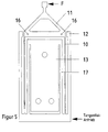
- FIG 5 is an embodiment of a micro force transducer shown.
- two soft spiral springs 10 are over the Coupling element 11 connected to a parallel spring system.
- the deflection this parallel spring arrangement is a measure of the tangential force F.
- Das Coupling element 11 is used when impressing as a force measuring system of the forces F in the glass plane.
- the path of deformation is determined by the Side elements 12 limited.
- the connection to the frame is made via the Pad 13 made.
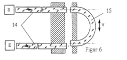
- Figure 6 shows the principle of the fiber optic force measuring arrangement, which in the elastic element is integrated and is used to measure the tangential force.
- the radiation generated by the transmitter S is transmitted via an optical waveguide 14 directed to the outlet opening and emitted there.
- the connecting body 15 which sits on the coupling 11 of the parallel spring arrangement, forwards the beams and also becomes a transmitter at its other end.
- the rays are picked up by the light-conducting body 14 connected to the receiver E and converted into an electrical signal.
- the light-guiding body 14 is preferably an optical waveguide.
- the inlet and outlet openings act as panels. This arrangement enables the linear range of the characteristic curve to be used with high sensitivity and the targeted suppression of the influence of disturbance variables.
- the light-conducting connecting body 15 is fastened in the two openings 16 of the coupling element II.
- the deflection caused by the force application F could be detected with an accuracy of approximately 100 nm.
- the resolution limit is approx. 10 nm. This results in an arrangement for measuring micro forces with a resolution of approx. 0.1 ⁇ N.
- the arrangement according to the invention enables a measuring range for the micro force measurement of 10 ⁇ N to 100 ⁇ N.
Landscapes
- Engineering & Computer Science (AREA)
- Automation & Control Theory (AREA)
- Physics & Mathematics (AREA)
- Health & Medical Sciences (AREA)
- Life Sciences & Earth Sciences (AREA)
- Chemical & Material Sciences (AREA)
- Analytical Chemistry (AREA)
- Biochemistry (AREA)
- General Health & Medical Sciences (AREA)
- General Physics & Mathematics (AREA)
- Immunology (AREA)
- Pathology (AREA)
- Force Measurement Appropriate To Specific Purposes (AREA)
Description
Im Stand der Technik sind verschiedene Ausführungen für Vorrichtungen zur genauen Untersuchung von Reibverhältnissen bekannt.
In Mittmann, Czichos: Reibungsmessungen und Oberflächenuntersuchungen an Kunststoff-Metall-Gleitpartnern; Materialprüfung 17, 1975, Nr.10, Okt., S.366, 367 ist eine Vorrichtung beschrieben, die als Stift-Scheibe-Triborneter ausgeführt ist. Dabei werden die Untersuchungen in einer abgeschlossenen, temperierbaren und mit einer definierten Gasen spülbaren Versuchskammer durchgeführt. Die Scheibe treibt ein tachogesteuerter Gleichstrommotor über ein zwischengeschaltetes Getriebe mit konstanter Geschwindigkeit an. Ein zylindrischer Stift aus PTFE, HDPE oder PETP wird vor der Untersuchung mit einem Mikrotom geschnitten. Der Stift wird mit einem Beobachtungsfernrohr parallel zu Scheibenoberfläche ausgerichtet. Als Kraftaufnehmer wird eine Anordnung aus vier Biegebalken verwendet.
Die Krafteinleitungsstellen und die Sensoren befinden sich jeweils an gegenüberliegenden Teilen des elastischen Biegeelementes.
Die für die Bestimmung der Reibungseigenschaften zwischen den Reibpartnern 1 und 2 notwendige Relativbewegung wird mit dem Tangentialantrieb 4 eingeprägt. Dadurch werden das elastische Element 3 und die Kraftangriffsfläche 1 derart bewegt, daß in Abhängigkeit von den Reibungsverhältnissen das elastische Element 3 der Antriebsbewegung nicht direkt folgen kann.
Das erfindungsgemäße elastische Element aus strukturiertem Glas weist gegenüber mit anderen Herstellungsmethoden und anderen Werkstoffen hergestellten Verformungskörpern wesentliche Vorteile auf.
Diese Anordnung ermöglicht die Ausnutzung des linearen Bereiches der Kennlinie mit hoher Empfindlichkeit sowie die gezielte Unterdrückung des Einflusses von Störgrößen. Die Befestigung des lichtleitenden Verbindungskörpers 15 erfolgt in den beiden Durchbrüchen 16 des Koppelelementes II. Die durch den Kraftangriff F hervorgerufene Auslenkung konnte mit einer Genauigkeit von ca. 100 nm detektiert werden. Die Grenze der Auflösung liegt bei ca. 10 nm.
Daraus ergibt sich eine Anordnung zur Messung von Mikrokräften mit einer Auflösung von ca. 0,1 µN. Die erfindungsgemäße Anordnung ermöglicht einen Meßbereich für die Mikrokraftmessung von 10 µN bis 100 µN.
- 1
- Kraftangriffsfläche
- 2
- Kraftableitungsfläche
- 3
- elastisches Biegeelement
- 4
- Tangentialantrieb
- 5
- Frontalantrieb
- 6
- Tangentialkraftsensor
- 7
- Signalverarbeitung
- 8
- Normalkraftführung und Verformungskörper
- 9
- Normalkraftsensor
- 10
- Biegefeder
- 11
- Koppelelement
- 12
- Seitenelement
- 13
- Anschlußfläche
- 14
- Lichtwellenleiter
- 15
- Verbindungskörper
- 16
- Durchbruch
- 17
- Tangentialführung
- F
- Kraftangriff
- E
- Empfänger für Lichtstrahlung
- S
- Sender für Lichtausstrahlung
Claims (7)
- Vorrichtung zur Untersuchung von Reibverhältnissen an Reibpartnern, mit der eine Normalkraft zwischen zwei zu untersuchende Reibungspartner eingeprägt und mit einem Normalkraftsensor (9) ermittelt wird und bei der die bei einer Relativbewegung zwischen den Reibpartnern wirkende Tangentialkraft mit einem Reibkraftsensor ermittelt wird, dadurch gekennzeichnet, daß der Kraftangriffspunkt für die Einleitung der Normalkraft und der Kraftangriffspunkt des Normalkraftsensor (9) über ein elastisches Biegeelement (3) miteinander verbunden sind, mit dem auch der Kraftangriffspunkt für die Einleitung der Tangentialkraft und der Reibkraftsensor verbunden sind, wobei die Verbindungen über Teilbereiche mit unterschiedlicher Biegesteifigkeit erfolgt und die beiden Teilbereiche um 90° versetzt angeordnet sind und bei dem das elastische Biegeelement (3) zwei Biegefedern (10), die über ein Koppelelement (11) zu einem weichen Parallelfederelement verbunden sind sowie eine dazu um 90° versetzt angeordnete steife Biegefeder enthält.
- Vorrichtung nach Anspruch 1, dadurch gekennzeichnet, daß das elastische Biegeelement (3) ein zusätzliches, härteres Parallelfederelement enthält, das zur Einleitung der Tangentialbewegung dient und das zwischen Normalkrafteinleitungspunkt und dem weichen Parallelfederelement angeordnet ist.
- Vorrichtung nach Anspruch 2, dadurch gekennzeichnet, daß in dem elastischen Biegeelement (3) Anschläge (12) zur Begrenzung der Linearbewegung des Parallelfederelement angebracht sind.
- Vorrichtung nach mindestens einem der vorhergehenden Ansprüche, dadurch gekennzeichnet, daß das elastische Biegeelement (3) ein in Ätztechnik hergestelltes Glasteil ist.
- Vorrichtung nach mindestens einem der vorhergehenden Ansprüche, dadurch gekennzeichnet, daß die Einleitung der Normalkraft mit einem Frontalantrieb (5) erfolgt, in dem eine Justiereinrichtung zur parallelen Ausrichtung der beiden Berührungsebenen der Reibungspartner integriert ist.
- Vorrichtung nach mindestens einem der vorhergehenden Ansprüche, dadurch gekennzeichnet, daß der Normalkraftsensor (9) und der Reibkraftsensor jeweils optische Wegsensoren sind, deren ausgegebene Signale in elektrische Signal umgewandelt und einer Signalverarbeitungseinheit (7) zugeführt werden.
- Vorrichtung nach mindestens einem der vorhergehenden Ansprüche, dadurch gekennzeichnet, daß der Reibkraftkraftsensor ein faseroptischer Sensor ist, bei dem mindestens ein Faserteil im elastischem Element (3) angebracht ist.
Applications Claiming Priority (3)
| Application Number | Priority Date | Filing Date | Title |
|---|---|---|---|
| DE19814911 | 1998-04-03 | ||
| DE19814911 | 1998-04-03 | ||
| PCT/DE1999/000981 WO1999051965A1 (de) | 1998-04-03 | 1999-03-31 | Vorrichtung zur untersuchung von reibverhältnissen |
Publications (2)
| Publication Number | Publication Date |
|---|---|
| EP1068508A1 EP1068508A1 (de) | 2001-01-17 |
| EP1068508B1 true EP1068508B1 (de) | 2002-04-24 |
Family
ID=7863445
Family Applications (1)
| Application Number | Title | Priority Date | Filing Date |
|---|---|---|---|
| EP99922083A Expired - Lifetime EP1068508B1 (de) | 1998-04-03 | 1999-03-31 | Vorrichtung zur untersuchung von reibverhältnissen |
Country Status (4)
| Country | Link |
|---|---|
| US (1) | US6666066B1 (de) |
| EP (1) | EP1068508B1 (de) |
| DE (2) | DE59901303D1 (de) |
| WO (1) | WO1999051965A1 (de) |
Families Citing this family (3)
| Publication number | Priority date | Publication date | Assignee | Title |
|---|---|---|---|---|
| FR2799547B1 (fr) * | 1999-10-06 | 2002-05-24 | Gradient Ass | Tribometre a disque pour la mesure des phenomenes tribologiques |
| US10613020B2 (en) * | 2017-08-10 | 2020-04-07 | The Boeing Company | Burr detection systems and methods |
| US20240319071A1 (en) * | 2023-02-28 | 2024-09-26 | The Florida State University Research Foundation, Inc. | Biaxial loadcell actuator for vacuum tribometer |
Family Cites Families (7)
| Publication number | Priority date | Publication date | Assignee | Title |
|---|---|---|---|---|
| US4646557A (en) * | 1986-02-28 | 1987-03-03 | Kavilco Corporation | Dynamic force measurement system |
| JPH076855B2 (ja) * | 1989-02-01 | 1995-01-30 | 小野田セメント株式会社 | 動摩擦力試験装置 |
| US5115664A (en) * | 1990-06-25 | 1992-05-26 | Ibm Corporation | Tunable feedback transducer for transient friction measurement |
| GB9218827D0 (en) * | 1992-09-05 | 1992-10-21 | Primelia Consulting Services L | Friction testing apparatus |
| US5400661A (en) | 1993-05-20 | 1995-03-28 | Advanced Mechanical Technology, Inc. | Multi-axis force platform |
| US5661235A (en) | 1993-10-01 | 1997-08-26 | Hysitron Incorporated | Multi-dimensional capacitive transducer |
| US5908981A (en) * | 1996-09-05 | 1999-06-01 | Board Of Trustees Of The Leland Stanford, Jr. University | Interdigital deflection sensor for microcantilevers |
-
1999
- 1999-03-31 US US09/647,436 patent/US6666066B1/en not_active Expired - Lifetime
- 1999-03-31 EP EP99922083A patent/EP1068508B1/de not_active Expired - Lifetime
- 1999-03-31 DE DE59901303T patent/DE59901303D1/de not_active Expired - Lifetime
- 1999-03-31 WO PCT/DE1999/000981 patent/WO1999051965A1/de not_active Ceased
- 1999-04-03 DE DE19915288A patent/DE19915288A1/de not_active Withdrawn
Also Published As
| Publication number | Publication date |
|---|---|
| DE59901303D1 (de) | 2002-05-29 |
| EP1068508A1 (de) | 2001-01-17 |
| US6666066B1 (en) | 2003-12-23 |
| DE19915288A1 (de) | 1999-10-14 |
| WO1999051965A1 (de) | 1999-10-14 |
Similar Documents
| Publication | Publication Date | Title |
|---|---|---|
| DE19514852C2 (de) | Verfahren und Anordnung zur Beschleunigungs- und Vibrationsmessung | |
| DE102019135732B4 (de) | Vorrichtung zur Messung einer Längenänderung | |
| EP4336143A2 (de) | Mikromechanisches messsystem zur messung von dehnungen an einem messobjekt und kompensation isotrop wirkender dehnung | |
| DE19922102B4 (de) | Faser-Bragg-Gitter-Sensoranordnung zur Ermittlung physikalischer Größen | |
| DE19939583A1 (de) | Bragg-Gitter-Vorrichtung zum Messen einer mechanischen Kraft sowie Anwendung und Verfahren zum Betrieb der Vorrichtung | |
| EP2580563A2 (de) | Verfahren zur schwingungsarmen optischen kraftmessung, insbesondere auch bei hohen temperaturen | |
| DE112020002417T5 (de) | Vorrichtung und Verfahren zum Überwachen der Integrität und Leistungsfähigkeit eines mechanischen Systems | |
| DE19915288A1 (de) | Vorrichtung zur Untersuchung von Reibverhältnissen | |
| EP1466157B1 (de) | Vorrichtung zur schwingungsarmen kraftmessung bei schnellen, dynamischen zugversuchen an werkstoffproben | |
| EP1903326B1 (de) | Vorrichtung zur Bestimmung von Torsionsmomenten im Submikronewtonmeterbereich | |
| DE10058498C2 (de) | Vorrichtung zur Bestimmung des Torsionsmoments und der Axialkraft in Torsionsversuchen an dünnen Fasern | |
| DE3709253C2 (de) | ||
| DE3422988A1 (de) | Verfahren und vorrichtung zum messen der querkontraktion einer laenglichen probe | |
| DE3514801C2 (de) | ||
| DE4405292C1 (de) | Justiereinrichtung für Rastersondenmikroskop | |
| WO2001014840A1 (de) | Bragg-gitter-vorrichtung zum messen einer mechanischen kraft sowie anwendung und verfahren zum betrieb der vorrichtung | |
| DE4309530A1 (de) | Vorrichtung für die dynamisch-mechanische Analyse | |
| DE3129847A1 (de) | "verfahren und anordnung zur messung mechanischer groessen" | |
| EP3563126B1 (de) | Akustik-emissionssensor | |
| DE69523206T2 (de) | Verfahren zur Messung der viskoelastischen Eigenschaften der polymerischen Beschichtungen von optischen Fasern | |
| JPS62231101A (ja) | 精密円筒形部品の検査用測定装置 | |
| WO2002088013A1 (de) | Fadenspannungsmesser, basierend auf einem fotolastischen messprinzip | |
| EP0410133B1 (de) | Vorrichtung zur Erfassung des in einer Welle übertragenen Drehmomentes, insbesondere bei einer zwischen einem Prüfling und einer Prüfmaschine angeordneten Welle | |
| DE4124685A1 (de) | Verfahren und anordnung zur messung einer mechanischen groesse | |
| DE1523214A1 (de) | Vorrichtung zur Bestimmung eines linearen Bewegungszustandes eines Gegenstandes |
Legal Events
| Date | Code | Title | Description |
|---|---|---|---|
| PUAI | Public reference made under article 153(3) epc to a published international application that has entered the european phase |
Free format text: ORIGINAL CODE: 0009012 |
|
| 17P | Request for examination filed |
Effective date: 20001007 |
|
| AK | Designated contracting states |
Kind code of ref document: A1 Designated state(s): CH DE FR GB LI |
|
| GRAG | Despatch of communication of intention to grant |
Free format text: ORIGINAL CODE: EPIDOS AGRA |
|
| REG | Reference to a national code |
Ref country code: GB Ref legal event code: IF02 |
|
| 17Q | First examination report despatched |
Effective date: 20011130 |
|
| GRAG | Despatch of communication of intention to grant |
Free format text: ORIGINAL CODE: EPIDOS AGRA |
|
| GRAH | Despatch of communication of intention to grant a patent |
Free format text: ORIGINAL CODE: EPIDOS IGRA |
|
| GRAH | Despatch of communication of intention to grant a patent |
Free format text: ORIGINAL CODE: EPIDOS IGRA |
|
| GRAA | (expected) grant |
Free format text: ORIGINAL CODE: 0009210 |
|
| AK | Designated contracting states |
Kind code of ref document: B1 Designated state(s): CH DE FR GB LI |
|
| PG25 | Lapsed in a contracting state [announced via postgrant information from national office to epo] |
Ref country code: FR Free format text: LAPSE BECAUSE OF FAILURE TO SUBMIT A TRANSLATION OF THE DESCRIPTION OR TO PAY THE FEE WITHIN THE PRESCRIBED TIME-LIMIT Effective date: 20020424 |
|
| REG | Reference to a national code |
Ref country code: GB Ref legal event code: FG4D Free format text: NOT ENGLISH |
|
| REG | Reference to a national code |
Ref country code: CH Ref legal event code: EP |
|
| REF | Corresponds to: |
Ref document number: 59901303 Country of ref document: DE Date of ref document: 20020529 |
|
| GBT | Gb: translation of ep patent filed (gb section 77(6)(a)/1977) |
Effective date: 20020718 |
|
| EN | Fr: translation not filed | ||
| PLBE | No opposition filed within time limit |
Free format text: ORIGINAL CODE: 0009261 |
|
| STAA | Information on the status of an ep patent application or granted ep patent |
Free format text: STATUS: NO OPPOSITION FILED WITHIN TIME LIMIT |
|
| PGFP | Annual fee paid to national office [announced via postgrant information from national office to epo] |
Ref country code: GB Payment date: 20030310 Year of fee payment: 5 |
|
| PGFP | Annual fee paid to national office [announced via postgrant information from national office to epo] |
Ref country code: CH Payment date: 20030401 Year of fee payment: 5 |
|
| 26N | No opposition filed |
Effective date: 20030127 |
|
| PG25 | Lapsed in a contracting state [announced via postgrant information from national office to epo] |
Ref country code: LI Free format text: LAPSE BECAUSE OF NON-PAYMENT OF DUE FEES Effective date: 20040331 Ref country code: GB Free format text: LAPSE BECAUSE OF NON-PAYMENT OF DUE FEES Effective date: 20040331 Ref country code: CH Free format text: LAPSE BECAUSE OF NON-PAYMENT OF DUE FEES Effective date: 20040331 |
|
| REG | Reference to a national code |
Ref country code: CH Ref legal event code: PL |
|
| GBPC | Gb: european patent ceased through non-payment of renewal fee | ||
| PGFP | Annual fee paid to national office [announced via postgrant information from national office to epo] |
Ref country code: DE Payment date: 20180124 Year of fee payment: 20 |
|
| REG | Reference to a national code |
Ref country code: DE Ref legal event code: R071 Ref document number: 59901303 Country of ref document: DE |