EP1067734A2 - Verfahren zur Überprüfung einer ringförmigen optischen Netzleitung zur Datenübertragung zwischen mehreren Netzteilnehmern in einem Kraftfahrzeug - Google Patents
Verfahren zur Überprüfung einer ringförmigen optischen Netzleitung zur Datenübertragung zwischen mehreren Netzteilnehmern in einem Kraftfahrzeug Download PDFInfo
- Publication number
- EP1067734A2 EP1067734A2 EP00113357A EP00113357A EP1067734A2 EP 1067734 A2 EP1067734 A2 EP 1067734A2 EP 00113357 A EP00113357 A EP 00113357A EP 00113357 A EP00113357 A EP 00113357A EP 1067734 A2 EP1067734 A2 EP 1067734A2
- Authority
- EP
- European Patent Office
- Prior art keywords
- network
- signal
- master function
- line
- ring
- Prior art date
- Legal status (The legal status is an assumption and is not a legal conclusion. Google has not performed a legal analysis and makes no representation as to the accuracy of the status listed.)
- Granted
Links
- 230000003287 optical effect Effects 0.000 title claims abstract description 115
- 230000005540 biological transmission Effects 0.000 title claims abstract description 43
- 238000000034 method Methods 0.000 title claims abstract description 29
- 238000012360 testing method Methods 0.000 claims abstract description 55
- 238000004891 communication Methods 0.000 claims abstract description 43
- 230000006870 function Effects 0.000 description 68
- 230000002950 deficient Effects 0.000 description 18
- 238000013024 troubleshooting Methods 0.000 description 7
- 230000008569 process Effects 0.000 description 5
- 238000003745 diagnosis Methods 0.000 description 4
- 239000013307 optical fiber Substances 0.000 description 4
- 239000000835 fiber Substances 0.000 description 3
- 230000009897 systematic effect Effects 0.000 description 3
- 230000008901 benefit Effects 0.000 description 2
- 230000007547 defect Effects 0.000 description 2
- 238000013461 design Methods 0.000 description 2
- 238000011156 evaluation Methods 0.000 description 2
- 238000002955 isolation Methods 0.000 description 2
- 230000008054 signal transmission Effects 0.000 description 2
- 230000007704 transition Effects 0.000 description 2
- RYGMFSIKBFXOCR-UHFFFAOYSA-N Copper Chemical compound [Cu] RYGMFSIKBFXOCR-UHFFFAOYSA-N 0.000 description 1
- 208000012886 Vertigo Diseases 0.000 description 1
- 238000007630 basic procedure Methods 0.000 description 1
- 230000008859 change Effects 0.000 description 1
- 230000003750 conditioning effect Effects 0.000 description 1
- 229910052802 copper Inorganic materials 0.000 description 1
- 239000010949 copper Substances 0.000 description 1
- 238000001514 detection method Methods 0.000 description 1
- 230000000694 effects Effects 0.000 description 1
- 238000005516 engineering process Methods 0.000 description 1
- 230000004807 localization Effects 0.000 description 1
- 238000012423 maintenance Methods 0.000 description 1
- 238000007726 management method Methods 0.000 description 1
- 230000006855 networking Effects 0.000 description 1
- 238000011056 performance test Methods 0.000 description 1
- 238000012545 processing Methods 0.000 description 1
- 230000004044 response Effects 0.000 description 1
- 238000012552 review Methods 0.000 description 1
- 230000005236 sound signal Effects 0.000 description 1
- 230000001360 synchronised effect Effects 0.000 description 1
- 238000010998 test method Methods 0.000 description 1
- 230000001960 triggered effect Effects 0.000 description 1
Images
Classifications
-
- H—ELECTRICITY
- H04—ELECTRIC COMMUNICATION TECHNIQUE
- H04B—TRANSMISSION
- H04B10/00—Transmission systems employing electromagnetic waves other than radio-waves, e.g. infrared, visible or ultraviolet light, or employing corpuscular radiation, e.g. quantum communication
- H04B10/27—Arrangements for networking
-
- H—ELECTRICITY
- H04—ELECTRIC COMMUNICATION TECHNIQUE
- H04B—TRANSMISSION
- H04B10/00—Transmission systems employing electromagnetic waves other than radio-waves, e.g. infrared, visible or ultraviolet light, or employing corpuscular radiation, e.g. quantum communication
- H04B10/27—Arrangements for networking
- H04B10/275—Ring-type networks
- H04B10/2755—Ring-type networks with a headend
-
- H—ELECTRICITY
- H04—ELECTRIC COMMUNICATION TECHNIQUE
- H04L—TRANSMISSION OF DIGITAL INFORMATION, e.g. TELEGRAPHIC COMMUNICATION
- H04L12/00—Data switching networks
- H04L12/28—Data switching networks characterised by path configuration, e.g. LAN [Local Area Networks] or WAN [Wide Area Networks]
- H04L12/40—Bus networks
- H04L12/403—Bus networks with centralised control, e.g. polling
-
- H—ELECTRICITY
- H04—ELECTRIC COMMUNICATION TECHNIQUE
- H04L—TRANSMISSION OF DIGITAL INFORMATION, e.g. TELEGRAPHIC COMMUNICATION
- H04L12/00—Data switching networks
- H04L12/28—Data switching networks characterised by path configuration, e.g. LAN [Local Area Networks] or WAN [Wide Area Networks]
- H04L12/42—Loop networks
-
- H—ELECTRICITY
- H04—ELECTRIC COMMUNICATION TECHNIQUE
- H04L—TRANSMISSION OF DIGITAL INFORMATION, e.g. TELEGRAPHIC COMMUNICATION
- H04L12/00—Data switching networks
- H04L12/28—Data switching networks characterised by path configuration, e.g. LAN [Local Area Networks] or WAN [Wide Area Networks]
- H04L12/44—Star or tree networks
-
- H—ELECTRICITY
- H04—ELECTRIC COMMUNICATION TECHNIQUE
- H04L—TRANSMISSION OF DIGITAL INFORMATION, e.g. TELEGRAPHIC COMMUNICATION
- H04L43/00—Arrangements for monitoring or testing data switching networks
- H04L43/50—Testing arrangements
-
- H—ELECTRICITY
- H04—ELECTRIC COMMUNICATION TECHNIQUE
- H04L—TRANSMISSION OF DIGITAL INFORMATION, e.g. TELEGRAPHIC COMMUNICATION
- H04L12/00—Data switching networks
- H04L12/28—Data switching networks characterised by path configuration, e.g. LAN [Local Area Networks] or WAN [Wide Area Networks]
- H04L12/40—Bus networks
- H04L2012/40267—Bus for use in transportation systems
- H04L2012/40273—Bus for use in transportation systems the transportation system being a vehicle
Definitions
- the invention relates to a method for checking a ring-shaped optical network cable for data transmission between several network participants in a motor vehicle.
- This network is built as a ring and connects the radio, CD changer, sound amplifier, telephone, cell phone and voice control system with each other via an optical data bus (D 2 B).
- Such communication and information systems require in Contrary to the previous asynchronous, so event-controlled data transmission as with the CAN bus synchronous data transmission with higher baud rates with optical signals can be transmitted.
- the radio can take over the master function as a network subscriber and at the same time serve as a bridge to the interior bus and diagnostic system.
- information can be transferred from the D 2 B system to other systems or vice versa, data from the vehicle to the D 2 B system.
- a particularly intensive exchange takes place between the instrument cluster and the network participant with the master function, since the D 2 B components can also be operated via the steering wheel and information is shown on the display of the instrument cluster.
- All audio signals such as music or speech are first transmitted digitally via the D 2 B bus either to the network participant with the master function or, if necessary, to the sound amplifier, where they are converted into an analog signal and reproduced via the vehicle loudspeakers. If a telephone system is installed in a vehicle, this has the advantage that no additional loudspeakers have to be accommodated for hands-free calling.
- this object is achieved by a method according to claim 1, after which a review of an annular optical network cable for data transmission between several Network participants in a motor vehicle, wherein a Network subscriber performs a master function by, in addition to the optical power line another communication line is present, which has a star-shaped structure and at that of the network participant with the master function at the center of the star-shaped structure and arranged over the Communication line with any other network participant directly is connected, a check of the optical Mains line takes place by the at the start of the operation optical power line in a first test step Start signal from the individual network participants Network participants with the master function via the Communication line is issued, the individual Network participants via the communication line the start signal acknowledge for the network participant with the master function, whereby after the start signal in a second test step of the network participant with the master function Initialization signal via the optical power line is output, with a proper operating state of the ring-shaped optical power line is detected when from that Network participants with the master function within one predetermined period of time via the optical power line Signal is received
- the target signal can be the initialization signal itself correspond.
- this is the test step the signal from the individual network participants just like that retransmit (possibly amplified) as received has been. It is also possible through the individual Network participants to change the signal characteristic, so that continued proper work by the individual Network subscriber becomes verifiable.
- a disturbance of the Power supply of a network subscriber or a Interruption of the connection via the communication line from the network participant with the master function to the Network node detected when the network node with the Master function no acknowledgment of the start signal by the corresponding network subscriber is received.
- a network participant sends a characterizing this network participant Fault location signal via the communication line if he no initialization signal via the optical power line has received, from the network participant with the Master function an error is detected that the transmission relates to an optical signal from the network subscriber who against the direction of transmission of the signal in the ring-shaped optical power line in front of the subscriber is arranged, which has emitted a fault location signal and in the direction of transmission of the ring-shaped optical Mains cable closest to the network participant with the Master function is arranged, or the reception of a optical signal by the network subscriber, who the Has emitted the fault location signal and the in Direction of transmission of the ring-shaped optical power line on next to the network participant with the master function or the ring-shaped optical power line between concerns the network participant who contrary to the Direction of transmission of the signal in the ring-shaped optical Power line is arranged in front of the network subscriber who Has emitted the fault location signal and the in Direction of transmission of the ring-shaped optical power line on next
- the optical Circulate signals in a ring So if with one Network subscriber no signal arrives, can from this Network participants are also no signal forwarded.
- the Network participants with the master function are at the Embodiment of the method according to claim 3, wherein the Error location signals of the individual participants via the Communication line are sent, fault location signals of all network participants received in the Direction of transmission of the ring-shaped optical power line lie behind the defect.
- the network subscriber who is in Direction of transmission of the ring-shaped optical power line on next to the network participant with the master function is arranged. After correcting this error, another Test process can be carried out.
- the other error entries can only be based on the fact that of the one No signals could be forwarded to network participants because this participant could not receive any signals. It So no further interference on the ring optical power line.
- a network subscriber sends an error signal characterizing this network participant via the optical power line if it is not Initialization signal received via the optical power line has, with the network participant with the master function an error is detected when this error signal is received, which emits an optical signal from the Network subscriber is concerned, the opposite of the transmission direction of the signal in the ring-shaped optical power line before Arranged participant who sent an error signal or has the receipt of an optical signal by the Concerns network subscriber who sent the error signal, or the ring-shaped optical power line between the Network subscriber is concerned, the opposite of the transmission direction of the signal in the ring-shaped optical power line before Network subscriber is arranged, which emits the error signal and this same subscriber, of which Network node with the master function detects an error, which emits an optical signal from the Network subscriber is concerned, the opposite of the transmission direction of the signal in the ring-shaped optical power line before Network subscriber with the master function is arranged or the receipt of an optical signal by the network subscriber with the master role or
- the error isolation is made by a signal via the circular optical power line is sent.
- the signal transmission through the ring-shaped optical power line is interrupted in several places.
- a fault first on the Recognized the point in the opposite direction of transmission annular optical power line closest to that Network node with the master function has occurred.
- This error can then be rectified after any further Errors are searched.
- time criteria can be set for this are such that a network participant recognizes that it is not a Has received the initialization signal if after a certain time threshold after the network participant Start signal received via the communication line, still no initialization signal from this network node was received. It is also possible from the network participant with the master function an error acknowledgment signal via the Send out communication line if from the network subscriber with the master function after sending the Initialization signal within a certain Time threshold still no signal via the ring-shaped optical Power line was received or only a signal that is not the Target signal corresponds.
- test device By compared to the normal operation of the network reduced functionality of the test device can be advantageous the effort in terms of logistics can be minimized because the network participants in the test phase with a test device are replaceable.
- the optical transmission is started via an additional communication line 7, which is designed as a copper line and is referred to below as a "wake-up" line.
- the respective component sends a wake-up pulse to everyone Ring participants.
- the wake-up line is between 50-100ms pulled to low level.
- the network participant Shortly after the wake-up pulse, the network participant starts with the master function 1 an initialization signal via the to send out annular optical power line 8. Is the annular optical power line 8 closed and is not electrical fault, the receiving side of the Network participant with master function 1 within 500ms lure, i.e. receive modulated light. This is the Communication between devices 1-6 via the ring-shaped optical power line 8 possible.
- the network participant sends with master function 1 the so-called target position message. Based on this Devices 2-6 determine their node address and message pass this on to the network subscriber via the actual position message the master function 1 known.
- the next step during the system startup phase is initializing the device addresses.
- the single ones Components 1-6 send a message to their own last Device address stored in memory to check whether there are other bus participants with the same address in the ring are. If this is not the case, it will be preset Address saved unchanged.
- the diagnosis of the D 2 B components such as telephone, CD changer and voice control device is carried out using a test device.
- the test device is connected via a communication line 8 to the network subscriber with the master function 1 (radio).
- the network device with the master function 1 serves as a connection between the test device and the other bus devices 2-6, and forwards the test device request via the ring-shaped optical power line 8 to the addressed control device 2-6.
- the response of the control unit 2-6 comes in the opposite way from the control unit 2-6 via the network subscriber used as a connection to the test device with the master function 1 to the test device.
- a code is assigned to all diagnosable errors. If an error occurs in a component, you can use the Test device read out and on the screen by specifying the Error codes and a brief description are displayed. Stored errors can be deleted with the test device.
- Next up Step requires the test device to establish a communication Test device.
- the one used as a connection to the test device Network subscriber with master function 1 shares using a Message ring participants 2-6 that the connection to Test device exists. After recognizing this message switches each component 2-6 in diagnostic mode.
- Test device used network participants with the master function 1 are used as a connection to the Test device used network participants with the master function 1 filed.
- This variant coding is sent from the test device to the network participants used as a connection to the test device sent to master function 1 and not there in one volatile memory.
- the as a connection to the test device used network participants with the master function 1 conducts this information on request from control units 2-6. This is a vehicle-specific self-configuration Devices 2-6 possible.
- the D 2 B system After installing the fiber optic cable set and all control units 2-6, the D 2 B system can be commissioned.
- the present invention advantageously shows that with the test device that with the network device with the Master role is linked without the help of Most of the fault patterns have already been identified using complex equipment can be.
- the wake-up For example, the test can be started using the test device.
- a wake-up is performed by the network subscriber with master function 1 500ms duration pulse sent. This start signal will of the other devices 2-6 as a start for the diagnosis of Communication line 7 interpreted. After 150ms the pulls Component 2 the communication line 7 for 50ms at low level and hereby indicates their presence. After 350ms leads Component 3 through the same process, etc.
- the network participant with master function 1 observes these processes and can hence the existence of the various components 2-6 log it by entering the sampled time values in a memory block. The test only works if the Ring not working.
- the memory is then read out by the test device and the result is displayed on the screen.
- each pulse corresponds to a D 2 B component 2-6. If a device 2-6 does not answer, either the communication line 7 is interrupted or the power supply is defective.
- the network subscriber sends with the Master function 1 after a switch-on condition is met a wake-up pulse as a start signal via the Communication line 7 to all participants 2-6 of the ring and begins to send an initialization signal across the ring to send optical power line 8.
- a wake-up pulse as a start signal via the Communication line 7 to all participants 2-6 of the ring and begins to send an initialization signal across the ring to send optical power line 8.
- RX diode Receives the RX diode after the fourth try no light, the changes Network nodes with master function 1 from master to Slave mode.
- the Network nodes with master function 1 can use this Message the number of participants after the break point determine and thus the last one in the backward direction of the bus Determine functioning control unit 2-6.
- the network participant with master function 1 writes the determined data in a memory, which in turn is read by the test device and am Screen can be displayed.
- the test device can advantageously recognize whether it is in a ring with nominal data traffic (active D 2 B OPTICAL system with user data traffic) and then forwards the received data to the subsequent bus segment.
- This function can be combined with the described procedure for localizing defective components in D 2 B OPTICAL systems in order to be able to localize an error locally.
- the network subscriber with the master function 1 sends a start signal via the communication line.
- This start signal is acknowledged by the individual network participants via the communication line, this acknowledgment being evaluated by the network participant using the master function 1.
- the result of this evaluation is a table with control units that have registered (current status).
- This table is then compared with another table with control units that should have logged on (target state).
- the target state was programmed as the configuration date when the D 2 B OPTICAL system was commissioned.
- An error state may be stored in an externally readable memory, preferably in the network participant with the master function 1.
- step 202 the network subscriber then uses the Master function 1 an initialization signal via the annular optical power line 8 sent out.
- a network subscriber can also advantageously use this Initialization signal can be activated if from this Network subscriber no start signal was received. This proves turns out to be advantageous if the connection via the Communication line 7 from the network participant with the Master function for the corresponding network participant is interrupted, the network subscriber including his Connection to the ring-shaped optical power line 8 in the rest but works flawlessly. In this case, during the normal operation a communication via the ring-shaped optical power line. During maintenance, the Bugs are fixed.
- step 203 it is then checked whether of the Network node with master function 1 is a target signal was received. If the individual network participants in the Initialization phase in the proper operation of the Transmit the initialization signal without changing this, this nominal signal corresponds to the initialization signal. If the initialization signal from the individual network participants characteristically changed to possibly further To be able to recognize error states corresponds to this Target signal certain changes in Initialization signal.
- the target signal If the target signal has been received, it can become a normal one Operating state to be transferred because of communication is possible via the ring-shaped optical power line.
- step 204 in which from the network node from which the initialization signal could not receive an error signal via the circular optical power line is sent. If of that Network participants with the master function 1 such Error signal can be received via the in the Network nodes with the master function 1 filed order the network participant (target state of the registered devices) "Last still functioning segment" of the ring recognized become. This can be done on the vehicle side in the network participant with the Master function or in the test device. The conclusion is then that the segment, which is logical before the last one that’s still working (i.e. that Segment that is opposite to the direction of transmission ring-shaped optical power line before the last one functioning segment), must have a defect because otherwise this segment is also recognized as OK. However, it is still not clear which components this segment (transmitter, receiver, fiber optic cable incl. Contact) have caused the error.
- step 205 in which the defective Component is determined. This may happen in several steps, each based on the results a determined decision for the possibly allow necessary next step.
- the recipient is first determined and then replaced by a test device. Now by turning on of the network participant with the master function of the ring and forced a bus ramp-up. Using the test device checks whether the received signal is sufficient. Is if so, it is indicated (step 206) that the Receiver that was replaced by the test device is defective.
- the receiver When checking by means of the test device, it emerged that no signal, a weak signal or a signal that does not correspond to the initialization signal, was received, the receiver is probably OK and the defective one Component is limited to optical fibers and transmitters.
- the transmitter of the defective segment is now replaced in step 207 with a further D 2 B network tester.
- the ring is woken up by switching on the network participant with the master function and a bus ramp-up is forced. It can then be determined, for example, by proper reception by the network subscriber with the master function, whether communication via the ring-shaped optical network line is now possible. The error can then be narrowed down to the corresponding transmitter in the segment. It is also possible to evaluate the signal from the test device that (still) replaces the receiver. If this signal is now recognized as sufficient, it can also be concluded that the transmitter is defective. In this case, after switching on the network participant with the master function, the ring will run up and all remaining control units will work. The error case is then displayed in step 208. The troubleshooting is then over.
- the initialization signal still could not or is not received correctly, so is outside of the recipient the transmitter is probably still fine and the defective Component is limited to the optical fiber. This is displayed in step 209.
- step 204 to receive an error signal from the network subscriber received with master function 1 can be closed that the receiver of the network subscriber with the Master function 1, the transmitter of the device, which is contrary to the Direction of transmission of the ring-shaped optical power line is arranged in front of the network participant with the master function 1 or the optical fiber between this device and the Network node with the master function is defective.
- the further one Troubleshooting is performed in the flowchart by block 210 hinted at in its component in terms of Procedure of the individual test steps the corresponding Corresponds to steps 205 to 209.
- step 201 started because another segment in the ring is defective could.
- the test device can be designed such that it is the receiver and can replace the transmitter individually. In the sense of Unification, the test device can also be designed that it can completely replace a network subscriber for the Start and initialization phase. In this case it is Test device with one receiver, one Signal conditioning circuit and a transmitter equipped. There Receiver and transmitter of a segment different Network participants can be assigned by such Replace also clearly identify the errors.
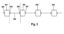
- FIG. 3 shows these relationships Network nodes 301, 306, 308 and 309, which are ring-shaped optical power line are connected, part of which with the Reference numeral 304 is provided.
- the network node 301 points a receiver 303 and a transmitter 302.
- the Network subscriber 306 has a receiver 307 and one Transmitter 305.
- the dash-dotted lines indicate that a segment in which an error may have occurred can be composed of elements 303, 304 and 305.
- the test device can be used for systematic troubleshooting be designed so that it can replace the receiver 303 or the transmitter 305.
- the test device can also be designed in this way be that there is a network node 301, 306, 308 and 309 together with the associated receiver and transmitter.
- the network node 301 When troubleshooting in the segment described, first the network node 301 replaced, which due to the previous error limitation can be checked whether the Receiver 303 is defective. By replacing the network subscriber 306 is due to the previous error isolation can be checked whether the transmitter 305 is defective.
Landscapes
- Engineering & Computer Science (AREA)
- Computer Networks & Wireless Communication (AREA)
- Signal Processing (AREA)
- Computing Systems (AREA)
- Physics & Mathematics (AREA)
- Electromagnetism (AREA)
- Small-Scale Networks (AREA)
- Optical Communication System (AREA)
Abstract
Description
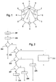
- Fig. 1
- Eine Prinzipdarstellung einer Anordnung mit einer ringförmigen optischen Netzleitung und einer Kommunikationsleitung,
- Fig. 2
- Einen Ablauf eines Prüfverfahrens und
- Fig. 3
- Eine Prinzipdarstellung, wie ein Testgerät einzelne Teile des Netzes ersetzen kann.
- Einschalten des Netzteilnehmers mit der Masterfunktion 1, also durch Drücken des Einschaltknopfes, Stecken oder Drehen des Zündschlüssels derart, dass die Zündung eingeschaltet wird.
- Über das Handy oder Telefon, z.B. durch einen ankommenden Anruf oder Wahl einer Telefonnummer.

- i=1
- CD-Wechsler
- i=2
- Telefon
- i=3
- Sprachbedienung
- i=4
- Amplifier Soundsystem
- i=5
- Handy
Claims (6)
- Verfahren zur Überprüfung einer ringförmigen optischen Netzleitung (8) zur Datenübertragung zwischen mehreren Netzteilnehmern (1-6, 301, 306, 308, 309) in einem Kraftfahrzeug, wobei ein Netzteilnehmer (1) eine Masterfunktion wahrnimmt,
dadurch gekennzeichnet, dass außer der optischen Netzleitung (8) eine weitere Kommunikationsleitung (7) vorhanden ist,wobei ein ordnungsgemäßer Betriebszustand der ringförmigen optischen Netzleitung (8) erkannt wird, wenn von dem Netzteilnehmer (1) mit der Masterfunktion innerhalb einer vorgegebenen Zeitspanne über die optische Netzleitung (8) ein Signal empfangen wird, das einem Sollsignal entspricht (203).die eine sternförmige Struktur aufweist undbei der der Netzteilnehmer (1) mit der Masterfunktionwobei eine Überprüfung der optischen Netzleitung (8) erfolgt, indem beim Start des Betriebes der optischen Netzleitung (8)im Zentrum der sternförmigen Struktur angeordnet undüber die Kommunikationsleitung (7) mit jedem anderen Netzteilnehmer (2-6) direkt verbunden ist,in einem ersten Prüfschrittein Startsignal an die einzelnen Netzteilnehmer (2-6) von dem Netzteilnehmer (1) mit der Masterfunktion über die Kommunikationsleitung (7) ausgegeben wird,wobei die einzelnen Netzteilnehmer (2-6) über die Kommunikationsleitung (7) das Startsignal für den Netzteilnehmer (1) mit der Masterfunktion quittieren (201),wobei nach dem Startsignal in einem zweiten Prüfschritt von dem Netzteilnehmer (1) mit der Masterfunktion ein Initialisierungssignal über die optische Netzleitung (8) ausgegeben wird (202), - Verfahren nach Anspruch 1,
dadurch gekennzeichnet, dass eine Störung der Spannungsversorgung eines Netzteilnehmers (2-6) bzw. eine Unterbrechung der Verbindung über die Kommunikationsleitung (7) von dem Netzteilnehmer (1) mit der Masterfunktion zu dem Netzteilnehmer (2-6) erkannt wird, wenn von dem Netzteilnehmer (1) mit der Masterfunktion keine Quittierung des Startsignals durch den entsprechenden Netzteilnehmer (2-6) empfangen wird (201). - Verfahren nach Anspruch 1 oder 2,
dadurch gekennzeichnet, dassein Netzteilnehmer (2-6) ein diesen Netzteilnehmer charakterisierendes Fehlerortungssignal über die Kommunikationsleitung (7) aussendet, wenn er kein Initialisierungssignal über die optische Netzleitung (8) empfangen hat,wobei von dem Netzteilnehmer (1) mit der Masterfunktion ein Fehler erkannt wird,oderder die Aussendung eines optischen Signals von dem Netzteilnehmer (2-6) betrifft,der entgegen der Übertragungsrichtung des Signals in der ringförmigen optischen Netzleitung (8) vor dem Netzteilnehmer (2-6) angeordnet ist, der ein Fehlerortungssignal ausgesandt hat undder in Übertragungsrichtung der ringförmigen optischen Netzleitung (8) am nächsten am Netzteilnehmer (1) mit der Masterfunktion angeordnet ist,oderder den Empfang eines optischen Signals durch den Netzteilnehmer (2-6) betrifft,der das Fehlerortungssignal ausgesandt hat undder in Übertragungsrichtung der ringförmigen optischen Netzleitung am nächsten am Netzteilnehmer (1) mit der Masterfunktion angeordnet ist,undder die ringförmige optische Netzleitung (8) zwischendem Netzteilnehmer (2-6) betrifft,der entgegen der Übertragungsrichtung des Signals in der ringförmigen optischen Netzleitung vor dem Netzteilnehmer (2-6) angeordnet ist,der das Fehlerortungssignal ausgesandt hat undder in Übertragungsrichtung der ringförmigen optischen Netzleitung (8) am nächsten am Netzteilnehmer (1) mit der Masterfunktion angeordnet ist,ebendiesem Netzteilnehmer (2-6),der das Fehlerortungssignal ausgesandt hat undin Übertragungsrichtung der ringförmigen optischen Netzleitung (8) am nächsten am Netzteilnehmer (1) mit der Masterfunktion angeordnet ist. - Verfahren nach Anspruch 1 oder 2,
dadurch gekennzeichnet, dassein Netzteilnehmer (2-6) ein diesen Netzteilnehmer (2-6) charakterisierendes Fehlersignal über die optische Netzleitung (8) aussendet (204), wenn er kein Initialisierungssignal über die optische Netzleitung (8) empfangen hat,wobei von dem Netzteilnehmer (1) mit der Masterfunktion bei einem Empfang dieses Fehlersignals ein Fehler erkannt wird,oderder die Aussendung eines optischen Signals von dem Netzteilnehmer (2-5) betrifft, der entgegen der Übertragungsrichtung des Signals in der ringförmigen optischen Netzleitung (8) vor dem Teilnehmer (2-6) angeordnet ist, der ein Fehlersignal ausgesandt hat (207, 208),oderder den Empfang eines optischen Signals durch den Netzteilnehmer (2-6) betrifft, der das Fehlersignal ausgesandt hat (205, 206),der die ringförmige optische Netzleitung (8) zwischenunddem Netzteilnehmer (1-5) betrifft, der entgegen der Übertragungsrichtung des Signals in der ringförmigen optischen Netzleitung (8) vor dem Netzteilnehmer (2-6) angeordnet ist, der das Fehlersignal ausgesandt hat,ebendiesem Netzteilnehmer (2-6), der das Fehlersignal ausgesandt hat (205, 207, 209),wobei von dem Netzteilnehmer (1) mit der Masterfunktion ein Fehler erkannt wird,oderder die Aussendung eines optischen Signals von dem Netzteilnehmer (6) betrifft, der entgegen der Übertragungsrichtung des Signals in der ringförmigen optischen Netzleitung (8) unmittelbar vor dem Netzteilnehmer (1) mit der Masterfunktion angeordnet istoderder den Empfang eines optischen Signals durch den Netzteilnehmer (1) mit der Masterfunktion betrifftder die ringförmige optische Netzleitung (8) zwischenunddem Netzteilnehmer (6) betrifft, der entgegen der Übertragungsrichtung des Signals in der ringförmigen optischen Netzleitung (8) unmittelbar vor dem Netzteilnehmer (1) mit der Masterfunktion angeordnet ist,wenn von dem Netzteilnehmer (1) mit der Masterfunktion kein Fehlersignal empfangen wird (204, 210).ebendiesem Netzteilnehmer (6), - Verfahren nach einem der vorhergehenden Ansprüche, dadurch gekennzeichnet, dass mittels eines Testgerätes ein Empfänger (303) oder ein Sender (305) eines Netzteilnehmers (301, 306) in deren Funktion in der Start- und Initialisierungsphase ersetzbar sind.
- Verfahren nach einem der vorhergehenden Ansprüche, dadurch gekennzeichnet, dass mittels eines Testgerätes ein Netzteilnehmer (301, 306, 308, 309) mit dem jeweils zugehörigen Empfänger und Sender (303, 302; 307, 305) in dessen Funktion in der Start- und Initialisierungsphase ersetzbar ist.
Applications Claiming Priority (2)
| Application Number | Priority Date | Filing Date | Title |
|---|---|---|---|
| DE19931838 | 1999-07-09 | ||
| DE19931838A DE19931838C1 (de) | 1999-07-09 | 1999-07-09 | Verfahren zur Überprüfung einer ringförmigen optischen Netzleitung zur Datenübertragung zwischen mehreren Netzteilnehmern in einem Kraftfahrzeug |
Publications (3)
| Publication Number | Publication Date |
|---|---|
| EP1067734A2 true EP1067734A2 (de) | 2001-01-10 |
| EP1067734A3 EP1067734A3 (de) | 2003-07-30 |
| EP1067734B1 EP1067734B1 (de) | 2004-11-24 |
Family
ID=7914087
Family Applications (1)
| Application Number | Title | Priority Date | Filing Date |
|---|---|---|---|
| EP00113357A Expired - Lifetime EP1067734B1 (de) | 1999-07-09 | 2000-06-23 | Verfahren zur Überprüfung einer ringförmigen optischen Netzleitung zur Datenübertragung zwischen mehreren Netzteilnehmern in einem Kraftfahrzeug |
Country Status (4)
| Country | Link |
|---|---|
| US (1) | US6643465B1 (de) |
| EP (1) | EP1067734B1 (de) |
| JP (1) | JP3524847B2 (de) |
| DE (2) | DE19931838C1 (de) |
Cited By (3)
| Publication number | Priority date | Publication date | Assignee | Title |
|---|---|---|---|---|
| DE102004032966A1 (de) * | 2004-07-07 | 2006-02-02 | Endress + Hauser (Deutschland) Holding Gmbh | Vorrichtung und Verfahren zur Überprüfung/Überwachung oder Analyse eines Kommunikationsnetzwerks |
| WO2008088787A3 (en) * | 2007-01-17 | 2008-10-02 | Lucent Technologies Inc | Star network control with mesh network payload delivery |
| DE102013004070B3 (de) * | 2013-03-11 | 2014-08-14 | Audi Ag | Verfahren zur Überprüfung eines Netzwerks und Netzwerkanordnung |
Families Citing this family (24)
| Publication number | Priority date | Publication date | Assignee | Title |
|---|---|---|---|---|
| DE10140852C5 (de) * | 2001-08-21 | 2016-11-17 | Robert Bosch Gmbh | Elektronisches System mit einem Lichtwellenleiter-Netzwerk und Verfahren zum Selbsttest sowie dazugehöriges Computerprogramm |
| DE10310302B4 (de) * | 2003-03-10 | 2007-05-16 | Knorr Bremse Systeme | Initialisierungsverfahren für eine Datenbusanordnung |
| DE10322828B4 (de) * | 2003-05-19 | 2007-12-20 | Daimlerchrysler Ag | Steuerungssystem für ein Fahrzeug |
| CN1739265A (zh) * | 2003-10-17 | 2006-02-22 | 松下电器产业株式会社 | 数据传输系统、数据传输设备及其方法 |
| DE102004042000A1 (de) * | 2004-08-31 | 2006-03-02 | Daimlerchrysler Ag | Energiemanagement mit Verbraucheranmeldung |
| US7317914B2 (en) * | 2004-09-24 | 2008-01-08 | Microsoft Corporation | Collaboratively locating disconnected clients and rogue access points in a wireless network |
| US7593344B2 (en) * | 2004-10-14 | 2009-09-22 | Temic Automotive Of North America, Inc. | System and method for reprogramming nodes in an automotive switch fabric network |
| US7623552B2 (en) * | 2004-10-14 | 2009-11-24 | Temic Automotive Of North America, Inc. | System and method for time synchronizing nodes in an automotive network using input capture |
| US7593429B2 (en) * | 2004-10-14 | 2009-09-22 | Temic Automotive Of North America, Inc. | System and method for time synchronizing nodes in an automotive network using input capture |
| US20060083172A1 (en) * | 2004-10-14 | 2006-04-20 | Jordan Patrick D | System and method for evaluating the performance of an automotive switch fabric network |
| US7599377B2 (en) * | 2004-10-15 | 2009-10-06 | Temic Automotive Of North America, Inc. | System and method for tunneling standard bus protocol messages through an automotive switch fabric network |
| US7613190B2 (en) * | 2004-10-18 | 2009-11-03 | Temic Automotive Of North America, Inc. | System and method for streaming sequential data through an automotive switch fabric |
| JP4733489B2 (ja) * | 2005-09-26 | 2011-07-27 | マイクロソフト コーポレーション | 隣接デバイスの共同作業による無線ネットワークにおけるパフォーマンスの問題の検出および診断 |
| US7968789B2 (en) * | 2005-12-30 | 2011-06-28 | International Optical Interface, Inc. | Method and apparatus for eye-safe transmittal of electrical power in vehicles using white light via plastic optical fiber |
| US7664579B2 (en) * | 2006-03-27 | 2010-02-16 | Eddie Sirhan | Test interface for diagnosing communication faults in automobiles |
| US7925166B2 (en) * | 2006-07-19 | 2011-04-12 | Vogley Wilbur C | Method and apparatus for phostonic stack system for vehicle control/sense |
| DE102007008044B4 (de) | 2007-02-17 | 2011-06-22 | Audi Ag, 85057 | Verkehrsmittel, Prüfgerät für ein Verkehrsmittel und Verfahren zum Einleiten einer Diagnosekommunikation zwischen einem Verkehrsmittel und einem Prüfgerät |
| US20090016713A1 (en) * | 2007-07-13 | 2009-01-15 | Tellabs Vienna Inc. | Method, apparatus, system, and computer program to debug an optical network terminal using diagnostic optical network terminal |
| EP2193635A4 (de) * | 2007-09-28 | 2011-08-31 | Allied Telesis Holdings Kk | Verfahren und vorrichtung zur verhinderung von netzwerkkonflikten |
| JP5651442B2 (ja) * | 2010-11-29 | 2015-01-14 | 矢崎総業株式会社 | 動作支援装置、電子機器、電子制御装置、及び、制御システム |
| DE102011080169A1 (de) * | 2011-08-01 | 2013-02-07 | Robert Bosch Gmbh | Kommunikationsanbindung für Sensorik in Fahrzeug-Regelsystemen |
| FR2983019B1 (fr) * | 2011-11-22 | 2014-01-03 | Thales Sa | Reseau de transmission d'informations et noeud de reseau associe |
| EP3627247B1 (de) * | 2018-09-18 | 2023-04-05 | KNORR-BREMSE Systeme für Nutzfahrzeuge GmbH | Steuerungsarchitektur für ein fahrzeug |
| JP7642586B2 (ja) * | 2022-05-02 | 2025-03-10 | 株式会社メガチップス | 通信システム、マスタ装置、スレーブ装置および通信方法 |
Family Cites Families (7)
| Publication number | Priority date | Publication date | Assignee | Title |
|---|---|---|---|---|
| US4930049A (en) * | 1988-12-27 | 1990-05-29 | General Electric Company | Optical multiplexed electrical distribution system particularly suited for vehicles |
| US5040168A (en) * | 1989-06-30 | 1991-08-13 | United Technologies Automotive, Inc. | Single wire, infrared, randomly reflected, vehicular multiplexing system |
| JP2880910B2 (ja) | 1994-05-26 | 1999-04-12 | 日本電気株式会社 | バス障害時の障害箇所特定装置 |
| DE19511178C2 (de) * | 1995-03-29 | 1998-08-13 | Phoenix Contact Gmbh & Co | Datenübertragungssystem mit Diagnosefunktion zur Fehlerortbestimmung |
| US5732086A (en) * | 1995-09-21 | 1998-03-24 | International Business Machines Corporation | System and method for determining the topology of a reconfigurable multi-nodal network |
| US5957985A (en) * | 1996-12-16 | 1999-09-28 | Microsoft Corporation | Fault-resilient automobile control system |
| GB9718722D0 (en) * | 1997-09-04 | 1997-11-12 | Comm & Control Electronics Ltd | Local communication system |
-
1999
- 1999-07-09 DE DE19931838A patent/DE19931838C1/de not_active Expired - Fee Related
-
2000
- 2000-06-23 EP EP00113357A patent/EP1067734B1/de not_active Expired - Lifetime
- 2000-06-23 DE DE50008725T patent/DE50008725D1/de not_active Expired - Lifetime
- 2000-06-30 US US09/607,654 patent/US6643465B1/en not_active Expired - Lifetime
- 2000-07-10 JP JP2000208300A patent/JP3524847B2/ja not_active Expired - Fee Related
Cited By (3)
| Publication number | Priority date | Publication date | Assignee | Title |
|---|---|---|---|---|
| DE102004032966A1 (de) * | 2004-07-07 | 2006-02-02 | Endress + Hauser (Deutschland) Holding Gmbh | Vorrichtung und Verfahren zur Überprüfung/Überwachung oder Analyse eines Kommunikationsnetzwerks |
| WO2008088787A3 (en) * | 2007-01-17 | 2008-10-02 | Lucent Technologies Inc | Star network control with mesh network payload delivery |
| DE102013004070B3 (de) * | 2013-03-11 | 2014-08-14 | Audi Ag | Verfahren zur Überprüfung eines Netzwerks und Netzwerkanordnung |
Also Published As
| Publication number | Publication date |
|---|---|
| JP2001045038A (ja) | 2001-02-16 |
| EP1067734B1 (de) | 2004-11-24 |
| DE50008725D1 (de) | 2004-12-30 |
| DE19931838C1 (de) | 2001-10-31 |
| JP3524847B2 (ja) | 2004-05-10 |
| EP1067734A3 (de) | 2003-07-30 |
| US6643465B1 (en) | 2003-11-04 |
Similar Documents
| Publication | Publication Date | Title |
|---|---|---|
| DE19931838C1 (de) | Verfahren zur Überprüfung einer ringförmigen optischen Netzleitung zur Datenübertragung zwischen mehreren Netzteilnehmern in einem Kraftfahrzeug | |
| EP2034668B1 (de) | Hochverfügbares Kommunikationssystem | |
| DE102006013578B4 (de) | Verfahren und Steuer- und Datenübertragungsanlage zum Überprüfen des Einbauortes eines sicheren Kommunikationsteilnehmers | |
| DE102015214993A1 (de) | Verfahren und Anordnung zur rückwirkungsfreien Übertragung von Daten zwischen Netzwerken | |
| DE19728061C2 (de) | Verfahren zur Steuerung der Nutzung von Satelliten-Übertragungskapazität zum Ersetzen gestörter Datenleitungen in terrestrischen Netzen und Schaltungsanordnung zur Durchführung des Verfahrens | |
| DE3139960C2 (de) | ||
| AT404656B (de) | Leitungsredundantes feldbussystem, vorzugsweise mit ringtopologie | |
| EP0395739B1 (de) | Verfahren zur steuerung und/oder überwachung und schaltungsanordnung zur durchführung des verfahrens | |
| EP1085705A2 (de) | Netzwerk mit mehreren Netzknoten und wenigstens einem Sternknoten | |
| EP1227406B1 (de) | Transceiver mit Mitteln zum Fehlermanagement | |
| EP1121785B1 (de) | Netzwerk sowie koppelgerät zur verbindung zweier segmente in einem derartigen netzwerk | |
| DE10146695B4 (de) | Verfahren zur Übertragung von Nachrichten zwischen Busteilnehmern | |
| EP0255069A1 (de) | Schaltungsanordnung zur seriellen Datenübertragung | |
| EP0163281A2 (de) | Verfahren zur Umschaltung zwischen redundanten Übertragungswegen | |
| EP3632049A1 (de) | Statussignalausgabe | |
| DE19511087B4 (de) | Verfahren und Anordnung zum automatischen Anschalten von Ersatzverbindungen über das IDSN-Netz bei gestörten Standverbindungen | |
| EP4094407A1 (de) | Sende-/empfangseinrichtung und kommunikationssteuereinrichtung für eine teilnehmerstation eines seriellen bussystems und verfahren zur kommunikation in einem seriellen bussystem | |
| EP0392245B1 (de) | Automatische Adressierung von zur Überwachung und/oder Steuerung in einem digitalen Nachrichtenübertragungssystem enthaltene Prozessoreinheiten | |
| EP3008607A1 (de) | Selektion eines schnittstellentyps | |
| EP2230745A1 (de) | Verfahren zur Fehlererkennung einer Energieerzeugungsanlage oder von Teilen einer Energieerzeugungsanlage, insbesondere einer PV-Anlage | |
| WO2001024569A1 (de) | System zum austausch von daten | |
| EP0143255B1 (de) | Verfahren und Schaltungsanordnung zur zeitlichen Überwachung des Belegtseins von Signalumsetzern | |
| EP0392246B1 (de) | Überwachungs- und Steuerungssystem für digitale Nachrichtenübertragungssysteme mit Master und Ersatzmaster | |
| EP0849908A2 (de) | Verfahren zur In-Betrieb-Überwachung eines Digitalübertragungssystems | |
| DE102018221417A1 (de) | Verfahren und Netzwerkverteiler zum Melden einer Störung in einem Kommunikationsnetzwerk |
Legal Events
| Date | Code | Title | Description |
|---|---|---|---|
| PUAI | Public reference made under article 153(3) epc to a published international application that has entered the european phase |
Free format text: ORIGINAL CODE: 0009012 |
|
| AK | Designated contracting states |
Kind code of ref document: A2 Designated state(s): AT BE CH CY DE DK ES FI FR GB GR IE IT LI LU MC NL PT SE |
|
| AX | Request for extension of the european patent |
Free format text: AL;LT;LV;MK;RO;SI |
|
| PUAL | Search report despatched |
Free format text: ORIGINAL CODE: 0009013 |
|
| AK | Designated contracting states |
Designated state(s): AT BE CH CY DE DK ES FI FR GB GR IE IT LI LU MC NL PT SE |
|
| AX | Request for extension of the european patent |
Extension state: AL LT LV MK RO SI |
|
| RIC1 | Information provided on ipc code assigned before grant |
Ipc: 7H 04L 12/26 B Ipc: 7B 60R 16/02 B Ipc: 7H 04L 12/437 B Ipc: 7H 04L 12/42 A Ipc: 7H 04L 12/44 B Ipc: 7H 04B 10/00 B |
|
| 17P | Request for examination filed |
Effective date: 20030704 |
|
| 17Q | First examination report despatched |
Effective date: 20030901 |
|
| AKX | Designation fees paid |
Designated state(s): DE FR GB IT SE |
|
| GRAP | Despatch of communication of intention to grant a patent |
Free format text: ORIGINAL CODE: EPIDOSNIGR1 |
|
| GRAS | Grant fee paid |
Free format text: ORIGINAL CODE: EPIDOSNIGR3 |
|
| GRAA | (expected) grant |
Free format text: ORIGINAL CODE: 0009210 |
|
| AK | Designated contracting states |
Kind code of ref document: B1 Designated state(s): DE FR GB IT SE |
|
| PG25 | Lapsed in a contracting state [announced via postgrant information from national office to epo] |
Ref country code: IT Free format text: LAPSE BECAUSE OF FAILURE TO SUBMIT A TRANSLATION OF THE DESCRIPTION OR TO PAY THE FEE WITHIN THE PRESCRIBED TIME-LIMIT;WARNING: LAPSES OF ITALIAN PATENTS WITH EFFECTIVE DATE BEFORE 2007 MAY HAVE OCCURRED AT ANY TIME BEFORE 2007. THE CORRECT EFFECTIVE DATE MAY BE DIFFERENT FROM THE ONE RECORDED. Effective date: 20041124 |
|
| REG | Reference to a national code |
Ref country code: GB Ref legal event code: FG4D Free format text: NOT ENGLISH |
|
| REF | Corresponds to: |
Ref document number: 50008725 Country of ref document: DE Date of ref document: 20041230 Kind code of ref document: P |
|
| REG | Reference to a national code |
Ref country code: IE Ref legal event code: FG4D Free format text: GERMAN |
|
| PG25 | Lapsed in a contracting state [announced via postgrant information from national office to epo] |
Ref country code: SE Free format text: LAPSE BECAUSE OF FAILURE TO SUBMIT A TRANSLATION OF THE DESCRIPTION OR TO PAY THE FEE WITHIN THE PRESCRIBED TIME-LIMIT Effective date: 20050224 |
|
| GBT | Gb: translation of ep patent filed (gb section 77(6)(a)/1977) |
Effective date: 20050218 |
|
| REG | Reference to a national code |
Ref country code: IE Ref legal event code: FD4D |
|
| PLBE | No opposition filed within time limit |
Free format text: ORIGINAL CODE: 0009261 |
|
| STAA | Information on the status of an ep patent application or granted ep patent |
Free format text: STATUS: NO OPPOSITION FILED WITHIN TIME LIMIT |
|
| ET | Fr: translation filed | ||
| 26N | No opposition filed |
Effective date: 20050825 |
|
| REG | Reference to a national code |
Ref country code: FR Ref legal event code: CD Ref country code: FR Ref legal event code: CA |
|
| PGFP | Annual fee paid to national office [announced via postgrant information from national office to epo] |
Ref country code: GB Payment date: 20110630 Year of fee payment: 12 |
|
| PGFP | Annual fee paid to national office [announced via postgrant information from national office to epo] |
Ref country code: FR Payment date: 20110722 Year of fee payment: 12 |
|
| PGFP | Annual fee paid to national office [announced via postgrant information from national office to epo] |
Ref country code: DE Payment date: 20110830 Year of fee payment: 12 |
|
| GBPC | Gb: european patent ceased through non-payment of renewal fee |
Effective date: 20120623 |
|
| REG | Reference to a national code |
Ref country code: FR Ref legal event code: ST Effective date: 20130228 |
|
| REG | Reference to a national code |
Ref country code: DE Ref legal event code: R119 Ref document number: 50008725 Country of ref document: DE Effective date: 20130101 |
|
| PG25 | Lapsed in a contracting state [announced via postgrant information from national office to epo] |
Ref country code: FR Free format text: LAPSE BECAUSE OF NON-PAYMENT OF DUE FEES Effective date: 20120702 Ref country code: DE Free format text: LAPSE BECAUSE OF NON-PAYMENT OF DUE FEES Effective date: 20130101 Ref country code: GB Free format text: LAPSE BECAUSE OF NON-PAYMENT OF DUE FEES Effective date: 20120623 |