EP1067686A2 - Saw resonator filter with bridged-t configuration - Google Patents
Saw resonator filter with bridged-t configuration Download PDFInfo
- Publication number
- EP1067686A2 EP1067686A2 EP00104656A EP00104656A EP1067686A2 EP 1067686 A2 EP1067686 A2 EP 1067686A2 EP 00104656 A EP00104656 A EP 00104656A EP 00104656 A EP00104656 A EP 00104656A EP 1067686 A2 EP1067686 A2 EP 1067686A2
- Authority
- EP
- European Patent Office
- Prior art keywords
- acoustic
- filter
- arm
- saw
- series
- Prior art date
- Legal status (The legal status is an assumption and is not a legal conclusion. Google has not performed a legal analysis and makes no representation as to the accuracy of the status listed.)
- Granted
Links
- 238000010897 surface acoustic wave method Methods 0.000 claims abstract description 100
- 238000010586 diagram Methods 0.000 description 7
- 238000004891 communication Methods 0.000 description 5
- 239000003990 capacitor Substances 0.000 description 4
- 101100478322 Caenorhabditis elegans sre-30 gene Proteins 0.000 description 1
- 239000013078 crystal Substances 0.000 description 1
- 238000013461 design Methods 0.000 description 1
- 238000011161 development Methods 0.000 description 1
- 230000003467 diminishing effect Effects 0.000 description 1
- 230000000694 effects Effects 0.000 description 1
- 238000005516 engineering process Methods 0.000 description 1
- 230000002349 favourable effect Effects 0.000 description 1
- 238000003780 insertion Methods 0.000 description 1
- 230000037431 insertion Effects 0.000 description 1
- 238000004519 manufacturing process Methods 0.000 description 1
- 239000000463 material Substances 0.000 description 1
- 238000000034 method Methods 0.000 description 1
- 238000010295 mobile communication Methods 0.000 description 1
- 238000012545 processing Methods 0.000 description 1
- 239000004065 semiconductor Substances 0.000 description 1
- 239000000758 substrate Substances 0.000 description 1
Images


Classifications
-
- H—ELECTRICITY
- H03—ELECTRONIC CIRCUITRY
- H03H—IMPEDANCE NETWORKS, e.g. RESONANT CIRCUITS; RESONATORS
- H03H9/00—Networks comprising electromechanical or electro-acoustic elements; Electromechanical resonators
- H03H9/25—Constructional features of resonators using surface acoustic waves
-
- H—ELECTRICITY
- H03—ELECTRONIC CIRCUITRY
- H03H—IMPEDANCE NETWORKS, e.g. RESONANT CIRCUITS; RESONATORS
- H03H9/00—Networks comprising electromechanical or electro-acoustic elements; Electromechanical resonators
- H03H9/46—Filters
- H03H9/64—Filters using surface acoustic waves
- H03H9/6423—Means for obtaining a particular transfer characteristic
- H03H9/6433—Coupled resonator filters
- H03H9/6483—Ladder SAW filters
Definitions
- the present invention relates to a surface-acoustic-wave filter of the resonator type, useful as a radio-frequency filter in a portable communication device.
- SAW filters are small and lightweight, require no adjustment, and can be manufactured In large quantities by the same photolithographic technology that is used to manufacture semiconductor devices. Moreover, the amplitude characteristics and phase characteristics of a SAW filter can be controlled independently. SAW filters are finding increasing use as picture-signal intermediate-frequency (PIF) filters, vestigial sideband (VSB) filters, and other types of communication filters, and as filters for digital signal processing.
- PIF picture-signal intermediate-frequency
- VSB vestigial sideband
- SAW filters are also used in the radio-frequency (RF) sections of portable telephone sets, where they have played a significant role in the achievement of improved performance and small size.
- the type of SAW filter that has been mainly used is a ladder filter employing SAW resonators. In addition to small size, this type of filter offers the advantages of narrow bandwidth, low insertion loss in the passband, and high attenuation in the adjacent stopbands, and it does not require a matching circuit.
- FIG. 1 shows a conventional ladder filter of the SAW resonator type, having two series-arm SAW resonators 11, 12, and one shunt-arm or parallel-arm SAW resonator 13.
- the series-arm SAW resonators 11, 12, referred to below as SR1 and SR2 are coupled in series between an input terminal 14 and an output terminal 15.
- the input terminal 14 is paired with a ground or earth (E) terminal 16 to form the input port of the filter.
- the output terminal 15 is paired with another ground terminal 17 to form the output port.
- the shunt-arm SAW resonator 13, referred to below as PR1 is coupled on one side to both ground terminals 16, 17, and on the other side to a node located between the two series-arm SAW resonators SR1 and SR2.
- Each SAW resonator SR1, SR2, PR1 comprises an interdigital transducer (IDT, not visible) flanked by a pair of grating reflectors (not visible).
- FIG. 2 shows an equivalent circuit of one half of the SAW filter in FIG. 1, representing each SAW resonator as a capacitance C 0 , equivalent to the capacitance of the IDT, paralleled by an inductance L in series with a capacitance C.
- This is also the equivalent circuit configuration that is used to represent a crystal resonator.
- a resonator that can be represented in this way has a reactance characteristic with both a resonance frequency and an antiresonance frequency.
- a bandpass filter can be created by a ladder configuration of such resonators, in the same way that an inductor-capacitor (LC) bandpass filter is configured, by making the antiresonance frequency of the shunt-arm resonator PRE11 substantially equal to the resonance frequency of the series-arm resonator SRE10.
- SRE10 represents SR1 in FIG. 1, while PRE11 represents half of PR1 in FIG. 1.
- the configuration in FIG. 1 is known as a T-type filter configuration.
- a T-type filter has relatively small attenuation, but the attenuation can be increased by adding more SAW resonator stages.
- portable telephones in a widely promoted code division multiple access (CDMA) system transmit in one band (824 to 849 megahertz or MHz) and receive in another band (869 to 894 MHz).
- CDMA code division multiple access
- the RF filters of these portable telephone sets must meet insertion-loss and attenuation requirements in these bands, and must also meet requirements for attenuation of spurious signals at two and three times the center frequency (2f c and 3f c )of these bands.
- SAW filters of the conventional ladder type cannot meet these spurious-signal attenuation requirements.
- a conventional solution to this problem is to provide a separate lumped-constant filter or a quarter-wave ( ⁇ /4) stripline inside the RF package to reject the spurious signal components, but it would obviously be preferable to have the spurious components eliminated by the SAW filter itself.
- the invented SAW filter has a T-type configuration with a series arm, a shunt arm, an input terminal, an output terminal, and a ground terminal.
- the series arm has a first SAW resonator and a second SAW resonator coupled in series between the input terminal and the output terminal.
- the shunt arm has a third SAW resonator coupled between the ground terminal and a node located between the first and second SAW resonators on the series arm.
- the SAW filter also has a fourth SAW resonator coupled between the input terminal and the output terminal, in parallel with the series arm.
- the fourth SAW resonator adds another pole to the attenuation characteristic of the SAW filter.
- This pole can be placed to provide additional attenuation at frequencies substantially equal to, or greater than, twice the center frequency of the passband of the SAW filter.
- the first embodiment is a SAW resonator filter suitable for use in a CDMA portable telephone set.
- the filter 20 has a bridged T configuration, comprising series-arm SAW resonators SR1 21 and SR2 22, a shunt-arm SAW resonator PR1 23, and a bridging SAW resonator BR1 24.
- the series-arm SAW resonators SR1, SR2 are coupled in series between an input terminal 25 and an output terminal 26.
- the bridging SAW resonator BR1 is also coupled between the input terminal 25 and output terminal 26, in parallel with the two series-arm SAW resonators SR1, SR2.
- the shunt-arm SAW resonator PR1 is coupled on one side to a pair of ground terminals 27, 28, and on the other side to a node 29 on the series arm between the two series-arm SAW resonators SR1, SR2. All four SAW resonators SR1, SR2, PR1, BR1 are formed on a single piezoelectric substrate or chip.
- the circuit configuration of this bridged-T filter 20 is that of a conventional T-type filter with a novel bridging SAW resonator BR1.
- the aperture, number of IDT electrode fingers, and resonance frequency of the bridging SAW resonator BR1 are selected so as to provide a certain attenuation at frequencies equal to two and three times the center frequency (f c ) of the passband of the filter 20, without affecting operation in the transmitting band (824-849 MHz) or receiving band (869-894 MHz).
- the other SAW resonators SR1, SR2, PR1 can be designed by the same techniques as used to design a ladder filter of the conventional T type.
- FIG. 4 is an equivalent lumped-constant circuit diagram corresponding to one half-section of the filter 20 in FIG. 3.
- BRE10(200) corresponds to half of the bridging SAW resonator BR1 in FIG. 3.
- SRE(210) corresponds to SAW resonator SR1 in FIG. 3.
- PRE30(220) corresponds to half of SAW resonator PR1 in FIG. 3.
- the black dots OUT(90), OUT (91), E(9) represent the output terminals of this half-section.
- S is the angular frequency of the input signal multiplied by the square root of minus one;
- L 200 , C 200 , and C 201 represent the inductance and capacitance values of the lumped inductor and capacitors in BRE10(200);
- L 210 , C 210 , and C 211 represent the inductance and capacitance values of the lumped inductor and capacitors in SRE30(210);
- L 220 , C 220 , and C 221 represent the inductance and capacitance values of the lumped inductor and capacitors in PRE30(220).
- the four SAW resonators BR1, SR1, SR2, PR1 in the first embodiment have the parameters shown in micrometers ( ⁇ m), nanohenries (nH), and picofarads (pF) in Table 1.
- the IDT in SAW resonator BR1 has twenty-two electrode fingers that mesh over a length or aperture of twenty-two micrometers (22 ⁇ m) and produce a pole of attenuation at a frequency of 1603 MHz, being equivalent to a 761.2-nH inductance coupled in series with a 0.0138-pF capacitance, paralleled by a 0.2-pF capacitance.
- the attenuation characteristic ATT( ⁇ ) of the filter 20 can be calculated from Zshort and Zopen by use of the following equation.
- the variable ⁇ represents the angular frequency of the input signal, and ABS indicates absolute value.
- ATT( ⁇ ) 20Log(ABS((Zopen + Zshort)/(Zopen - Zshort)))
- poles of attenuation are obtained only under the following conditions:
- the conventional T-type filter in FIG. 1 is obtainable from the filter 20 in FIG. 3 by the following settings, which remove a pole of attenuation.
- the performance of the conventional T-type SAW filter and the invented SAW filter 20 was simulated by lumped-constant equivalent circuits, using the parameters given in Table 1 for both filters, with BR1 omitted from the conventional filter.
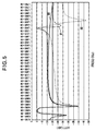
- the results shown in FIG. 5 were obtained.
- Input frequency is indicated in hertz on the horizontal axis, using exponential notation (8.12E+08 indicates 8.12 ⁇ 10 8 Hz, or 812 MHz).
- Attenuation is indicated in decibels (dB) on the vertical axis.
- the solid line 30 is the attenuation characteristic of the conventional T-type filter in FIG. 1.
- the dash-dot line 31 is the attenuation characteristic of the filter 20 in the first embodiment.
- the first embodiment provides an equivalent capability on the SAW filter chip itself, enabling the dimensions of the RF package to be reduced.
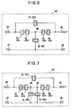
- the second embodiment is a filter 40 having four series-arm SAW resonators SR1 41, SR2 42, SR3 43, and SR4 44.
- the shunt-arm SAW resonator PR1 23, bridging SAW resonator BR1 24, input and output terminals 25, 26, and ground terminals 27, 28 are as described in the first embodiment.
- the shunt-arm SAW resonator PR1 is coupled to a node 29 between series-arm SAW resonators SR2 and SR3.
- the bridging SAW resonator BR1 is coupled to the input and output terminals 25, 26, in parallel with the series arm.
- the SAW resonators in the second embodiment have the parameters listed in Table 2, Ap meaning aperture.
- the attenuation characteristic of the second embodiment was simulated on the basis of lumped constants with the values Indicated in Table 2. The result is indicated by the dotted line 32 in FIG. 5.
- poles of attenuation are present on both sides of the CDMA receiving band (at 850 MHz and 920 MHz), and a little below the 2f c spurious frequency (at 1600 MHz). Attenuation in the 2f c and 3f c spurious bands is much higher than in the first embodiment, however.
- the second embodiment provides excellent rejection of spurious signals without the use of additional components in the RF package.
- the third embodiment is a filter 50 that adds a second shunt-arm SAW resonator PR2 52 to the configuration of the second embodiment.
- the second shunt-arm SAW resonator PR2 is coupled in parallel with the first shunt-arm SAW resonator PR1 to the node 29 between series-arm SAW resonators SR2 and SR3, and to the ground terminals 27, 28. Spurious-signal attenuation effects similar to those in the second embodiment are obtained.
- the embodiments above When used as RF filters in CDMA communication devices such as portable telephones, the embodiments above enable 2f c and 3f c spurious-band attenuation requirements to be met without the use of additional components that would increase the size of the RF package.
- the second and third embodiments enable very favorable spurious-signal rejection performance to be achieved in a small RF package.
- the invention is not limited to the specific ladder filter configurations illustrated by the above embodiments, but can be practiced in any filter configuration having a series arm and a shunt arm coupled in a T configuration, by inserting an additional SAW resonator between the input and output terminals, in parallel with the series arm.
- Applications of the invention are not limited to CDMA communication equipment.
Landscapes
- Physics & Mathematics (AREA)
- Acoustics & Sound (AREA)
- Surface Acoustic Wave Elements And Circuit Networks Thereof (AREA)
- Piezo-Electric Or Mechanical Vibrators, Or Delay Or Filter Circuits (AREA)
Abstract
Description
| Resonator | BR1 | SR1 | SR2 | PR1 |
| Aperture (µm):fingers | 22:22 | 100:100 | 100:100 | 100:100 |
| Pole frequency (MHz) | 1603 | 918.1 | 918.1 | 853.1 |
| Equivalent L1 (nH) | 761.2 | 182 | 182 | 113 |
| Equivalent C1 (pF) | 0.0138 | 0.176 | 0.176 | 0.308 |
| Equivalent C0 (pF) | 0.2 | 2.67 | 2.67 | 3.90 |
| Resonator | BR1 | SR1 | SR2 | SR3 | SR4 | PR1 |
| Ap:fingers | 22:22 | 100:100 | 100:100 | 100:100 | 100:100 | 100:100 |
| Pole (MHz) | 1603 | 918.1 | 928 | 918.1 | 928 | 858 |
| Eq. L1 (nH) | 761.2 | 182 | 180.0 | 182 | 180 | 112.4 |
| Eq. C1 (pF) | 0.0138 | 0.176 | 0.174 | 0.176 | 0.174 | 0.308 |
| Eq. C0 (pF) | 0.02 | 2.67 | 2.64 | 2.67 | 2.64 | 3.88 |
Claims (5)
- A surface-acoustic-wave filter (20) having a T-type configuration with a series arm, a shunt arm, an input terminal (25), an output terminal (26), and a ground terminal (27), the series arm having a node (29), a first surface-acoustic-wave resonator (21) coupled between said node and the input terminal, and a second surface-acoustic-wave resonator (22) coupled between said node and the output terminal, the shunt arm having a third surface-acoustic-wave resonator (23) coupled between said node and the ground terminal, the third surface-acoustic-wave resonator having an antiresonance frequency, the first surface-acoustic-wave resonator having a resonance frequency substantially equal to said antiresonance frequency, the surface-acoustic-wave filter also comprising:a fourth surface-acoustic-wave resonator (24) coupled between the input terminal (25) and the output terminal (26), in parallel with the series arm.
- The surface-acoustic-wave filter (40) of claim 1, wherein the series arm has a fifth surface-acoustic-wave resonator (42) coupled in series with the first surface-acoustic-wave resonator (41) between the input terminal (25) and said node (29).
- The surface-acoustic-wave filter (40) of claim 1 or 2, wherein the series arm has a fifth surface-acoustic-wave resonator (44) coupled in series with the second surface-acoustic-wave resonator (43) between said node (29) and the output terminal (26).
- The surface-acoustic-wave filter (40) of claim 1, wherein the series arm has a fifth surface-acoustic-wave resonator (42) coupled in series with the first surface-acoustic-wave resonator (41) between the input terminal (25) and said node (29), and a sixth surface-acoustic-wave resonator (44) coupled in series with the second surface-acoustic-wave resonator (43) between said node (29) and the output terminal (26).
- The surface-acoustic-wave filter (50) of one of claims 1 to 4, wherein the shunt arm has a seventh surface-acoustic-wave resonator (52) coupled in parallel with the third surface-acoustic-wave resonator (51) between said node (29) and the ground terminal (27).
Applications Claiming Priority (2)
| Application Number | Priority Date | Filing Date | Title |
|---|---|---|---|
| JP19592899 | 1999-07-09 | ||
| JP11195928A JP2001024475A (en) | 1999-07-09 | 1999-07-09 | Surface acoustic wave filter |
Publications (3)
| Publication Number | Publication Date |
|---|---|
| EP1067686A2 true EP1067686A2 (en) | 2001-01-10 |
| EP1067686A3 EP1067686A3 (en) | 2004-06-30 |
| EP1067686B1 EP1067686B1 (en) | 2010-06-30 |
Family
ID=16349318
Family Applications (1)
| Application Number | Title | Priority Date | Filing Date |
|---|---|---|---|
| EP00104656A Expired - Lifetime EP1067686B1 (en) | 1999-07-09 | 2000-03-03 | Saw resonator filter with bridged-t configuration |
Country Status (5)
| Country | Link |
|---|---|
| US (1) | US6377140B1 (en) |
| EP (1) | EP1067686B1 (en) |
| JP (1) | JP2001024475A (en) |
| KR (1) | KR100804460B1 (en) |
| DE (1) | DE60044597D1 (en) |
Families Citing this family (123)
| Publication number | Priority date | Publication date | Assignee | Title |
|---|---|---|---|---|
| JP4056798B2 (en) * | 2002-06-06 | 2008-03-05 | 沖電気工業株式会社 | Surface acoustic wave filter |
| DE10304470B4 (en) * | 2003-02-04 | 2013-09-05 | Epcos Ag | Electronic surface acoustic wave device |
| JP5441095B2 (en) * | 2008-01-31 | 2014-03-12 | 太陽誘電株式会社 | Elastic wave device, duplexer, communication module, and communication apparatus |
| JPWO2010125934A1 (en) * | 2009-04-30 | 2012-10-25 | 株式会社村田製作所 | Elastic wave device |
| US9270254B2 (en) | 2011-09-30 | 2016-02-23 | Qualcomm Mems Technologies, Inc. | Cross-sectional dilation mode resonators and resonator-based ladder filters |
| WO2016158094A1 (en) * | 2015-04-01 | 2016-10-06 | 株式会社村田製作所 | Duplexer |
| KR101626470B1 (en) | 2015-09-16 | 2016-06-01 | (주)계림건축사사무소 | Non-foam type materials for reducing noise and floor system comprising the same |
| US10700666B2 (en) * | 2017-02-08 | 2020-06-30 | Taiyo Yuden Co., Ltd. | Filter circuit, multiplexer, and module |
| US11206009B2 (en) | 2019-08-28 | 2021-12-21 | Resonant Inc. | Transversely-excited film bulk acoustic resonator with interdigital transducer with varied mark and pitch |
| US11936358B2 (en) | 2020-11-11 | 2024-03-19 | Murata Manufacturing Co., Ltd. | Transversely-excited film bulk acoustic resonator with low thermal impedance |
| US10601392B2 (en) | 2018-06-15 | 2020-03-24 | Resonant Inc. | Solidly-mounted transversely-excited film bulk acoustic resonator |
| US11323089B2 (en) | 2018-06-15 | 2022-05-03 | Resonant Inc. | Filter using piezoelectric film bonded to high resistivity silicon substrate with trap-rich layer |
| US11323090B2 (en) | 2018-06-15 | 2022-05-03 | Resonant Inc. | Transversely-excited film bulk acoustic resonator using Y-X-cut lithium niobate for high power applications |
| US12088281B2 (en) | 2021-02-03 | 2024-09-10 | Murata Manufacturing Co., Ltd. | Transversely-excited film bulk acoustic resonator with multi-mark interdigital transducer |
| US10756697B2 (en) | 2018-06-15 | 2020-08-25 | Resonant Inc. | Transversely-excited film bulk acoustic resonator |
| US12040779B2 (en) | 2020-04-20 | 2024-07-16 | Murata Manufacturing Co., Ltd. | Small transversely-excited film bulk acoustic resonators with enhanced Q-factor |
| US10637438B2 (en) | 2018-06-15 | 2020-04-28 | Resonant Inc. | Transversely-excited film bulk acoustic resonators for high power applications |
| US11509279B2 (en) | 2020-07-18 | 2022-11-22 | Resonant Inc. | Acoustic resonators and filters with reduced temperature coefficient of frequency |
| US10790802B2 (en) | 2018-06-15 | 2020-09-29 | Resonant Inc. | Transversely excited film bulk acoustic resonator using rotated Y-X cut lithium niobate |
| US11929731B2 (en) | 2018-02-18 | 2024-03-12 | Murata Manufacturing Co., Ltd. | Transversely-excited film bulk acoustic resonator with optimized electrode mark, and pitch |
| US11323096B2 (en) | 2018-06-15 | 2022-05-03 | Resonant Inc. | Transversely-excited film bulk acoustic resonator with periodic etched holes |
| US11146232B2 (en) | 2018-06-15 | 2021-10-12 | Resonant Inc. | Transversely-excited film bulk acoustic resonator with reduced spurious modes |
| US12237826B2 (en) | 2018-06-15 | 2025-02-25 | Murata Manufacturing Co., Ltd. | Transversely-excited film bulk acoustic resonator with optimized electrode thickness, mark, and pitch |
| US12009798B2 (en) | 2018-06-15 | 2024-06-11 | Murata Manufacturing Co., Ltd. | Transversely-excited film bulk acoustic resonators with electrodes having irregular hexagon cross-sectional shapes |
| US10917072B2 (en) | 2019-06-24 | 2021-02-09 | Resonant Inc. | Split ladder acoustic wave filters |
| US12119808B2 (en) | 2018-06-15 | 2024-10-15 | Murata Manufacturing Co., Ltd. | Transversely-excited film bulk acoustic resonator package |
| US11996822B2 (en) | 2018-06-15 | 2024-05-28 | Murata Manufacturing Co., Ltd. | Wide bandwidth time division duplex transceiver |
| US11264966B2 (en) | 2018-06-15 | 2022-03-01 | Resonant Inc. | Solidly-mounted transversely-excited film bulk acoustic resonator with diamond layers in Bragg reflector stack |
| US12463619B2 (en) | 2018-06-15 | 2025-11-04 | Murata Manufacturing Co., Ltd. | Filter device |
| US12113512B2 (en) | 2021-03-29 | 2024-10-08 | Murata Manufacturing Co., Ltd. | Layout of XBARs with multiple sub-resonators in parallel |
| US11349452B2 (en) | 2018-06-15 | 2022-05-31 | Resonant Inc. | Transversely-excited film bulk acoustic filters with symmetric layout |
| US12212306B2 (en) | 2018-06-15 | 2025-01-28 | Murata Manufacturing Co., Ltd. | Transversely-excited film bulk acoustic resonator with multiple diaphragm thicknesses and fabrication method |
| US11728785B2 (en) | 2018-06-15 | 2023-08-15 | Murata Manufacturing Co., Ltd. | Transversely-excited film bulk acoustic resonator using pre-formed cavities |
| US11171629B2 (en) | 2018-06-15 | 2021-11-09 | Resonant Inc. | Transversely-excited film bulk acoustic resonator using pre-formed cavities |
| US11949402B2 (en) | 2020-08-31 | 2024-04-02 | Murata Manufacturing Co., Ltd. | Resonators with different membrane thicknesses on the same die |
| US12191838B2 (en) | 2018-06-15 | 2025-01-07 | Murata Manufacturing Co., Ltd. | Solidly-mounted transversely-excited film bulk acoustic device and method |
| US12191837B2 (en) | 2018-06-15 | 2025-01-07 | Murata Manufacturing Co., Ltd. | Solidly-mounted transversely-excited film bulk acoustic device |
| US11146238B2 (en) | 2018-06-15 | 2021-10-12 | Resonant Inc. | Film bulk acoustic resonator fabrication method |
| US11201601B2 (en) | 2018-06-15 | 2021-12-14 | Resonant Inc. | Transversely-excited film bulk acoustic resonator with multiple diaphragm thicknesses and fabrication method |
| US11228296B2 (en) | 2018-06-15 | 2022-01-18 | Resonant Inc. | Transversely-excited film bulk acoustic resonator with a cavity having a curved perimeter |
| US12155374B2 (en) | 2021-04-02 | 2024-11-26 | Murata Manufacturing Co., Ltd. | Tiled transversely-excited film bulk acoustic resonator high power filters |
| US12237827B2 (en) | 2018-06-15 | 2025-02-25 | Murata Manufacturing Co., Ltd. | Solidly-mounted transversely-excited film bulk acoustic filters with multiple piezoelectric plate thicknesses |
| US11967945B2 (en) | 2018-06-15 | 2024-04-23 | Murata Manufacturing Co., Ltd. | Transversly-excited film bulk acoustic resonators and filters |
| US11909381B2 (en) | 2018-06-15 | 2024-02-20 | Murata Manufacturing Co., Ltd. | Transversely-excited film bulk acoustic resonators with two-layer electrodes having a narrower top layer |
| US11901878B2 (en) | 2018-06-15 | 2024-02-13 | Murata Manufacturing Co., Ltd. | Transversely-excited film bulk acoustic resonators with two-layer electrodes with a wider top layer |
| US11374549B2 (en) | 2018-06-15 | 2022-06-28 | Resonant Inc. | Filter using transversely-excited film bulk acoustic resonators with divided frequency-setting dielectric layers |
| US11916539B2 (en) | 2020-02-28 | 2024-02-27 | Murata Manufacturing Co., Ltd. | Split-ladder band N77 filter using transversely-excited film bulk acoustic resonators |
| US11323095B2 (en) | 2018-06-15 | 2022-05-03 | Resonant Inc. | Rotation in XY plane to suppress spurious modes in XBAR devices |
| US11876498B2 (en) | 2018-06-15 | 2024-01-16 | Murata Manufacturing Co., Ltd. | Transversely-excited film bulk acoustic resonator with multiple diaphragm thicknesses and fabrication method |
| US11323091B2 (en) | 2018-06-15 | 2022-05-03 | Resonant Inc. | Transversely-excited film bulk acoustic resonator with diaphragm support pedestals |
| US11349450B2 (en) | 2018-06-15 | 2022-05-31 | Resonant Inc. | Symmetric transversely-excited film bulk acoustic resonators with reduced spurious modes |
| US12149227B2 (en) | 2018-06-15 | 2024-11-19 | Murata Manufacturing Co., Ltd. | Transversely-excited film bulk acoustic resonator package |
| US12155371B2 (en) | 2021-03-29 | 2024-11-26 | Murata Manufacturing Co., Ltd. | Layout of xbars with multiple sub-resonators in series |
| US12081187B2 (en) | 2018-06-15 | 2024-09-03 | Murata Manufacturing Co., Ltd. | Transversely-excited film bulk acoustic resonator |
| US11888463B2 (en) | 2018-06-15 | 2024-01-30 | Murata Manufacturing Co., Ltd. | Multi-port filter using transversely-excited film bulk acoustic resonators |
| US11329628B2 (en) | 2020-06-17 | 2022-05-10 | Resonant Inc. | Filter using lithium niobate and lithium tantalate transversely-excited film bulk acoustic resonators |
| US10826462B2 (en) | 2018-06-15 | 2020-11-03 | Resonant Inc. | Transversely-excited film bulk acoustic resonators with molybdenum conductors |
| US12119805B2 (en) | 2018-06-15 | 2024-10-15 | Murata Manufacturing Co., Ltd. | Substrate processing and membrane release of transversely-excited film bulk acoustic resonator using a sacrificial tub |
| US12040781B2 (en) | 2018-06-15 | 2024-07-16 | Murata Manufacturing Co., Ltd. | Transversely-excited film bulk acoustic resonator package |
| US12184261B2 (en) | 2018-06-15 | 2024-12-31 | Murata Manufacturing Co., Ltd. | Transversely-excited film bulk acoustic resonator with a cavity having round end zones |
| US12224732B2 (en) | 2018-06-15 | 2025-02-11 | Murata Manufacturing Co., Ltd. | Solidly-mounted transversely-excited film bulk acoustic resonators and filters for 27 GHz communications bands |
| JP7328751B2 (en) | 2018-11-06 | 2023-08-17 | 太陽誘電株式会社 | Highpass filters and multiplexers |
| US11329626B2 (en) | 2018-11-30 | 2022-05-10 | Resonant Inc. | Bandpass filter with improved upper band edge sharpness |
| DE112020001227B4 (en) | 2019-03-14 | 2026-05-13 | Murata Manufacturing Co., Ltd. | Transversely excited acoustic film resonator with lambda-half dielectric layer |
| US11901873B2 (en) | 2019-03-14 | 2024-02-13 | Murata Manufacturing Co., Ltd. | Transversely-excited film bulk acoustic resonator with partial BRAGG reflectors |
| WO2020206433A1 (en) | 2019-04-05 | 2020-10-08 | Resonant Inc. | Transversely-excited film bulk acoustic resonator package and method |
| US10911021B2 (en) | 2019-06-27 | 2021-02-02 | Resonant Inc. | Transversely-excited film bulk acoustic resonator with lateral etch stop |
| US12034423B2 (en) | 2019-06-27 | 2024-07-09 | Murata Manufacturing Co., Ltd | XBAR frontside etch process using polysilicon sacrificial layer |
| US12506462B2 (en) | 2020-02-28 | 2025-12-23 | Murata Manufacturing Co., Ltd. | Transversely-excited film bulk acoustic resonator with multi-pitch interdigital transducer |
| US12255625B2 (en) | 2020-02-28 | 2025-03-18 | Murata Manufacturing Co., Ltd. | Filter using transversely-excited film bulk acoustic resonators with inductively coupled sub-resonators |
| US12341490B2 (en) | 2020-04-20 | 2025-06-24 | Murata Manufacturing Co., Ltd. | Low loss transversely-excited film bulk acoustic resonators and filters |
| US12341493B2 (en) | 2020-04-20 | 2025-06-24 | Murata Manufacturing Co., Ltd. | Low loss transversely-excited film bulk acoustic resonators and filters |
| US12278617B2 (en) | 2020-04-20 | 2025-04-15 | Murata Manufacturing Co., Ltd. | High Q solidly-mounted transversely-excited film bulk acoustic resonators |
| US11811391B2 (en) | 2020-05-04 | 2023-11-07 | Murata Manufacturing Co., Ltd. | Transversely-excited film bulk acoustic resonator with etched conductor patterns |
| US11469733B2 (en) | 2020-05-06 | 2022-10-11 | Resonant Inc. | Transversely-excited film bulk acoustic resonators with interdigital transducer configured to reduce diaphragm stress |
| US12074584B2 (en) | 2020-05-28 | 2024-08-27 | Murata Manufacturing Co., Ltd. | Transversely-excited film bulk acoustic resonators with two-layer electrodes |
| US12267062B2 (en) | 2020-06-17 | 2025-04-01 | Murata Manufacturing Co., Ltd. | Transversely-excited film bulk acoustic resonators with three-layer electrodes |
| US11482981B2 (en) | 2020-07-09 | 2022-10-25 | Resonanat Inc. | Transversely-excited film bulk acoustic resonators with piezoelectric diaphragm supported by piezoelectric substrate |
| US11264969B1 (en) | 2020-08-06 | 2022-03-01 | Resonant Inc. | Transversely-excited film bulk acoustic resonator comprising small cells |
| US11271539B1 (en) | 2020-08-19 | 2022-03-08 | Resonant Inc. | Transversely-excited film bulk acoustic resonator with tether-supported diaphragm |
| US11671070B2 (en) | 2020-08-19 | 2023-06-06 | Murata Manufacturing Co., Ltd. | Transversely-excited film bulk acoustic resonators using multiple dielectric layer thicknesses to suppress spurious modes |
| US11894835B2 (en) | 2020-09-21 | 2024-02-06 | Murata Manufacturing Co., Ltd. | Sandwiched XBAR for third harmonic operation |
| US11476834B2 (en) | 2020-10-05 | 2022-10-18 | Resonant Inc. | Transversely-excited film bulk acoustic resonator matrix filters with switches in parallel with sub-filter shunt capacitors |
| US11929733B2 (en) | 2020-10-05 | 2024-03-12 | Murata Manufacturing Co., Ltd. | Transversely-excited film bulk acoustic resonator matrix filters with input and output impedances matched to radio frequency front end elements |
| US11405017B2 (en) | 2020-10-05 | 2022-08-02 | Resonant Inc. | Acoustic matrix filters and radios using acoustic matrix filters |
| US11658639B2 (en) | 2020-10-05 | 2023-05-23 | Murata Manufacturing Co., Ltd. | Transversely-excited film bulk acoustic resonator matrix filters with noncontiguous passband |
| US11728784B2 (en) | 2020-10-05 | 2023-08-15 | Murata Manufacturing Co., Ltd. | Transversely-excited film bulk acoustic resonator matrix filters with split die sub-filters |
| US12119806B2 (en) | 2020-10-30 | 2024-10-15 | Murata Manufacturing Co., Ltd. | Transversely-excited film bulk acoustic resonator with spiral interdigitated transducer fingers |
| US12003226B2 (en) | 2020-11-11 | 2024-06-04 | Murata Manufacturing Co., Ltd | Transversely-excited film bulk acoustic resonator with low thermal impedance |
| US12255617B2 (en) | 2020-11-11 | 2025-03-18 | Murata Manufacturing Co., Ltd. | Solidly-mounted transversely-excited film bulk acoustic resonators with low thermal impedance |
| US12431856B2 (en) | 2020-11-12 | 2025-09-30 | Murata Manufacturing Co., Ltd. | Transversely-excited film bulk acoustic resonator with reduced loss in the aperture direction |
| US12255626B2 (en) | 2020-11-13 | 2025-03-18 | Murata Manufacturing Co., Ltd. | Solidly-mounted transversely-excited film bulk acoustic filters with excess piezoelectric material removed |
| US11496113B2 (en) | 2020-11-13 | 2022-11-08 | Resonant Inc. | XBAR devices with excess piezoelectric material removed |
| US11405020B2 (en) | 2020-11-26 | 2022-08-02 | Resonant Inc. | Transversely-excited film bulk acoustic resonators with structures to reduce acoustic energy leakage |
| US11239816B1 (en) | 2021-01-15 | 2022-02-01 | Resonant Inc. | Decoupled transversely-excited film bulk acoustic resonators |
| US12126318B2 (en) | 2021-01-15 | 2024-10-22 | Murata Manufacturing Co., Ltd. | Filters using decoupled transversely-excited film bulk acoustic resonators |
| US12463615B2 (en) | 2021-01-21 | 2025-11-04 | Murata Manufacturing Co., Ltd | Transversely-excited film bulk acoustic resonators with improved coupling and reduced energy leakage |
| US12308826B2 (en) | 2021-02-03 | 2025-05-20 | Murata Manufacturing Co., Ltd. | Bandpass filters using transversely-excited film bulk acoustic resonators |
| US12113510B2 (en) | 2021-02-03 | 2024-10-08 | Murata Manufacturing Co., Ltd. | Transversely-excited film bulk acoustic resonators with multiple piezoelectric membrane thicknesses on the same chip |
| US12308825B2 (en) | 2021-02-12 | 2025-05-20 | Murata Manufacturing Co., Ltd | Transversely-excited film bulk acoustic resonators with narrow gaps between busbars and ends of interdigital transducer fingers |
| US12289099B2 (en) | 2021-03-24 | 2025-04-29 | Murata Manufacturing Co., Ltd. | Acoustic filters with shared acoustic tracks for series and shunt resonators |
| US12107568B2 (en) | 2021-03-24 | 2024-10-01 | Murata Manufacturing Co., Ltd. | Composite transversely-excited film bulk acoustic resonator circuits having a capacitor for improved rejection |
| US12348216B2 (en) | 2021-03-24 | 2025-07-01 | Murata Manufacturing Co., Ltd. | Acoustic filters with shared acoustic tracks and cascaded series resonators |
| US12126328B2 (en) | 2021-03-24 | 2024-10-22 | Murata Manufacturing Co., Ltd. | Acoustic filters with shared acoustic tracks |
| US12355426B2 (en) | 2021-03-24 | 2025-07-08 | Murata Manufacturing Co., Ltd. | Acoustic filters with shared acoustic tracks |
| US12341492B2 (en) | 2021-03-29 | 2025-06-24 | Murata Manufacturing Co., Ltd. | Transversely-excited film bulk acoustic resonators with busbar side edges that form angles with a perimeter of the cavity |
| US12224735B2 (en) | 2021-03-30 | 2025-02-11 | Murata Manufacturing Co., Ltd. | Diplexer using decoupled transversely-excited film bulk acoustic resonators |
| WO2022212569A1 (en) | 2021-03-30 | 2022-10-06 | Resonant Inc. | Filter for 6 ghz wi-fi using transversely-excited film bulk acoustic resonators |
| US12237823B2 (en) | 2021-04-02 | 2025-02-25 | Murata Manufacturing Co., Ltd. | Transversely-excited film bulk acoustic resonators with solidly mounted resonator (SMR) pedestals |
| US12249971B2 (en) | 2021-04-02 | 2025-03-11 | Murata Manufacturing Co., Ltd. | Transversely-excited film bulk acoustic resonators with solidly mounted resonator (SMR) pedestals |
| US12255633B2 (en) | 2021-04-16 | 2025-03-18 | Murata Manufacturing Co., Ltd. | Filter using transversely-excited film bulk acoustic resonators |
| US12199584B2 (en) | 2021-04-16 | 2025-01-14 | Murata Manufacturing Co., Ltd. | Transversely-excited film bulk acoustic resonator fabrication using wafer-to-wafer bonding |
| US12160220B2 (en) | 2021-04-30 | 2024-12-03 | Murata Manufacturing Co., Ltd. | Transversely-excited film bulk acoustic resonator with oxide strip acoustic confinement structures |
| US12255607B2 (en) | 2021-04-30 | 2025-03-18 | Murata Manufacturing Co., Ltd. | Transversely-excited film bulk acoustic resonator with buried oxide strip acoustic confinement structures |
| US12075700B2 (en) | 2021-05-07 | 2024-08-27 | Murata Manufacturing Co., Ltd. | Transversely-excited film bulk acoustic resonator fabrication using polysilicon pillars |
| US12057823B2 (en) | 2021-05-07 | 2024-08-06 | Murata Manufacturing Co., Ltd. | Transversely-excited film bulk acoustic resonator with concentric interdigitated transducer fingers |
| US12170513B2 (en) | 2021-06-30 | 2024-12-17 | Murata Manufacturing Co., Ltd. | Transversely-excited film bulk acoustic resonator with reduced substrate to contact bump thermal resistance |
| US12620961B2 (en) | 2021-07-31 | 2026-05-05 | Murata Manufacturing Co., Ltd. | Patterned cavity walls for transversely-excited film bulk acoustic resonator frontside membrane release |
| US12603639B2 (en) | 2021-08-02 | 2026-04-14 | Murata Manufacturing Co., Ltd. | Metal cavity for transversely-excited film bulk acoustic resonator (XBAR) |
| US12456962B2 (en) | 2021-09-24 | 2025-10-28 | Murata Manufacturing Co., Ltd. | Transversely-excited film bulk acoustic resonators wafer-level packaging using a dielectric cover |
| US12451864B2 (en) | 2021-09-29 | 2025-10-21 | Murata Manufacturing Co., Ltd. | Transversely-excited film bulk acoustic resonators with curved shaped ends of fingers or opposing busbars |
| US12225387B2 (en) | 2021-09-29 | 2025-02-11 | Murata Manufacturing Co., Ltd. | Communications device with concurrent operation in 5GHZ and 6GHZ U-NII frequency ranges |
| US12407326B2 (en) | 2021-11-04 | 2025-09-02 | Murata Manufacturing Co., Ltd. | Stacked die transversely-excited film bulk acoustic resonator (XBAR) filters |
Family Cites Families (13)
| Publication number | Priority date | Publication date | Assignee | Title |
|---|---|---|---|---|
| JP2800905B2 (en) | 1991-10-28 | 1998-09-21 | 富士通株式会社 | Surface acoustic wave filter |
| JP3388475B2 (en) | 1991-12-16 | 2003-03-24 | 富士通株式会社 | Duplexer |
| US5847626A (en) * | 1994-02-22 | 1998-12-08 | Matsushita Electric Industrial Co., Ltd. | Balanced-type surface acoustic wave lattice filter |
| DE69608997T2 (en) * | 1995-04-12 | 2000-11-16 | Matsushita Electric Industrial Co., Ltd. | Resonator chain filter with surface acoustic waves |
| JPH09167937A (en) * | 1995-12-18 | 1997-06-24 | Oki Electric Ind Co Ltd | Surface acoustic wave filter |
| JP3887037B2 (en) * | 1996-05-27 | 2007-02-28 | 株式会社東芝 | Surface acoustic wave filter device |
| US5939957A (en) * | 1996-07-26 | 1999-08-17 | Ngk Spark Plug Co., Ltd. | 6-elements ladder type piezoelectric filter |
| JP3378151B2 (en) * | 1996-09-17 | 2003-02-17 | 沖電気工業株式会社 | Surface acoustic wave filter circuit |
| JP3746579B2 (en) * | 1996-11-29 | 2006-02-15 | 沖電気工業株式会社 | SAW filter |
| DE69722168T2 (en) * | 1997-02-12 | 2003-12-18 | Oki Electric Ind Co Ltd | Acoustic surface wave filters with generated damping poles by impedance circuits |
| JP3285790B2 (en) * | 1997-05-13 | 2002-05-27 | 富士通株式会社 | Oscillator circuit |
| TW404091B (en) * | 1997-05-16 | 2000-09-01 | Murata Manufacturing Co | Ladder filter having edge-reflection type resonators |
| FI108583B (en) * | 1998-06-02 | 2002-02-15 | Nokia Corp | resonator structures |
-
1999
- 1999-07-09 JP JP11195928A patent/JP2001024475A/en active Pending
-
2000
- 2000-03-03 EP EP00104656A patent/EP1067686B1/en not_active Expired - Lifetime
- 2000-03-03 DE DE60044597T patent/DE60044597D1/en not_active Expired - Lifetime
- 2000-03-08 KR KR1020000011582A patent/KR100804460B1/en not_active Expired - Lifetime
- 2000-03-15 US US09/526,490 patent/US6377140B1/en not_active Expired - Fee Related
Also Published As
| Publication number | Publication date |
|---|---|
| US6377140B1 (en) | 2002-04-23 |
| EP1067686B1 (en) | 2010-06-30 |
| KR100804460B1 (en) | 2008-02-20 |
| DE60044597D1 (en) | 2010-08-12 |
| KR20010014545A (en) | 2001-02-26 |
| JP2001024475A (en) | 2001-01-26 |
| EP1067686A3 (en) | 2004-06-30 |
Similar Documents
| Publication | Publication Date | Title |
|---|---|---|
| US6377140B1 (en) | Saw resonator filter with bridged-T configuration | |
| US10727805B2 (en) | Multiplexer including filters with resonators and parallel inductor | |
| KR102294095B1 (en) | Multiplexers, high-frequency front-end circuits and communication devices | |
| KR100434411B1 (en) | Surface acoustic wave device | |
| US7339445B2 (en) | BAW duplexer without phase shifter | |
| US10193527B2 (en) | Branching filter | |
| JP5673818B2 (en) | Duplexer | |
| KR19980070285A (en) | Surface acoustic wave filters with attenuation poles generated by impedance circuits | |
| US7486158B2 (en) | Branching filter | |
| US20180234078A1 (en) | Tunable filter, radio frequency front-end circuit, and communication apparatus | |
| CN112311354B (en) | Filter circuit and composite filter device | |
| CN113890503A (en) | Filter device, multiplexer, and communication device | |
| JP3337073B2 (en) | Surface acoustic wave device | |
| US11146229B2 (en) | Filter and multiplexer | |
| JP3746579B2 (en) | SAW filter | |
| JP3465630B2 (en) | Antenna duplexer and communication device | |
| CN118214390A (en) | Filters, multiplexers and RF front-end modules | |
| CN112671362A (en) | FBAR filter | |
| CN212163294U (en) | Extraction device | |
| CN112217494B (en) | Composite filter device | |
| JP3181158B2 (en) | Composite surface acoustic wave filter and mobile communication device using composite surface acoustic wave filter | |
| JPH07231241A (en) | Surface acoustic wave device | |
| US7864002B2 (en) | Filter device with balanced signal input and output terminals | |
| JP4147646B2 (en) | Transmission band division type surface acoustic wave duplexer | |
| JP3398243B2 (en) | Antenna duplexer |
Legal Events
| Date | Code | Title | Description |
|---|---|---|---|
| PUAI | Public reference made under article 153(3) epc to a published international application that has entered the european phase |
Free format text: ORIGINAL CODE: 0009012 |
|
| AK | Designated contracting states |
Kind code of ref document: A2 Designated state(s): AT BE CH CY DE DK ES FI FR GB GR IE IT LI LU MC NL PT SE |
|
| AX | Request for extension of the european patent |
Free format text: AL;LT;LV;MK;RO;SI |
|
| PUAL | Search report despatched |
Free format text: ORIGINAL CODE: 0009013 |
|
| AK | Designated contracting states |
Kind code of ref document: A3 Designated state(s): AT BE CH CY DE DK ES FI FR GB GR IE IT LI LU MC NL PT SE |
|
| AX | Request for extension of the european patent |
Extension state: AL LT LV MK RO SI |
|
| 17P | Request for examination filed |
Effective date: 20041220 |
|
| AKX | Designation fees paid |
Designated state(s): DE FR GB |
|
| 17Q | First examination report despatched |
Effective date: 20080128 |
|
| GRAP | Despatch of communication of intention to grant a patent |
Free format text: ORIGINAL CODE: EPIDOSNIGR1 |
|
| GRAS | Grant fee paid |
Free format text: ORIGINAL CODE: EPIDOSNIGR3 |
|
| GRAA | (expected) grant |
Free format text: ORIGINAL CODE: 0009210 |
|
| AK | Designated contracting states |
Kind code of ref document: B1 Designated state(s): DE FR GB |
|
| REG | Reference to a national code |
Ref country code: GB Ref legal event code: FG4D |
|
| REF | Corresponds to: |
Ref document number: 60044597 Country of ref document: DE Date of ref document: 20100812 Kind code of ref document: P |
|
| PLBE | No opposition filed within time limit |
Free format text: ORIGINAL CODE: 0009261 |
|
| STAA | Information on the status of an ep patent application or granted ep patent |
Free format text: STATUS: NO OPPOSITION FILED WITHIN TIME LIMIT |
|
| 26N | No opposition filed |
Effective date: 20110331 |
|
| REG | Reference to a national code |
Ref country code: DE Ref legal event code: R097 Ref document number: 60044597 Country of ref document: DE Effective date: 20110330 |
|
| REG | Reference to a national code |
Ref country code: DE Ref legal event code: R081 Ref document number: 60044597 Country of ref document: DE Owner name: LAPIS SEMICONDUCTOR CO., LTD., JP Free format text: FORMER OWNER: OKI ELECTRIC INDUSTRY CO., LTD., TOKYO, JP Effective date: 20111109 Ref country code: DE Ref legal event code: R081 Ref document number: 60044597 Country of ref document: DE Owner name: INTELLECTUAL VENTURES FUND 77 LLC (N.D.GES.D.S, US Free format text: FORMER OWNER: OKI ELECTRIC INDUSTRY CO., LTD., TOKYO, JP Effective date: 20111109 |
|
| REG | Reference to a national code |
Ref country code: DE Ref legal event code: R082 Ref document number: 60044597 Country of ref document: DE Representative=s name: BETTEN & RESCH, DE |
|
| REG | Reference to a national code |
Ref country code: DE Ref legal event code: R082 Ref document number: 60044597 Country of ref document: DE Representative=s name: BETTEN & RESCH PATENT- UND RECHTSANWAELTE PART, DE Effective date: 20120309 Ref country code: DE Ref legal event code: R081 Ref document number: 60044597 Country of ref document: DE Owner name: INTELLECTUAL VENTURES FUND 77 LLC (N.D.GES.D.S, US Free format text: FORMER OWNER: OKI SEMICONDUCTOR CO.,LTD., TOKYO, JP Effective date: 20120309 Ref country code: DE Ref legal event code: R082 Ref document number: 60044597 Country of ref document: DE Representative=s name: PATENTANWAELTE BETTEN & RESCH, DE Effective date: 20120309 |
|
| REG | Reference to a national code |
Ref country code: FR Ref legal event code: TP Owner name: LAPIS SEMICONDUCTOR CO., LTD., JP Effective date: 20120412 |
|
| REG | Reference to a national code |
Ref country code: GB Ref legal event code: 732E Free format text: REGISTERED BETWEEN 20120419 AND 20120425 |
|
| REG | Reference to a national code |
Ref country code: FR Ref legal event code: CL Name of requester: MURATA MANUFACTURING CO., LTD., JP Effective date: 20120413 |
|
| REG | Reference to a national code |
Ref country code: GB Ref legal event code: 732E Free format text: REGISTERED BETWEEN 20120705 AND 20120711 |
|
| REG | Reference to a national code |
Ref country code: DE Ref legal event code: R082 Ref document number: 60044597 Country of ref document: DE Representative=s name: BETTEN & RESCH PATENT- UND RECHTSANWAELTE PART, DE Effective date: 20120823 Ref country code: DE Ref legal event code: R081 Ref document number: 60044597 Country of ref document: DE Owner name: INTELLECTUAL VENTURES FUND 77 LLC (N.D.GES.D.S, US Free format text: FORMER OWNER: LAPIS SEMICONDUCTOR CO., LTD., TOKYO, JP Effective date: 20120823 Ref country code: DE Ref legal event code: R082 Ref document number: 60044597 Country of ref document: DE Representative=s name: PATENTANWAELTE BETTEN & RESCH, DE Effective date: 20120823 |
|
| REG | Reference to a national code |
Ref country code: FR Ref legal event code: TP Owner name: JINTELLECTUAL VENTURES FUND 77 LLC, US Effective date: 20130107 |
|
| REG | Reference to a national code |
Ref country code: FR Ref legal event code: PLFP Year of fee payment: 17 |
|
| REG | Reference to a national code |
Ref country code: FR Ref legal event code: PLFP Year of fee payment: 18 |
|
| REG | Reference to a national code |
Ref country code: FR Ref legal event code: PLFP Year of fee payment: 19 |
|
| PGFP | Annual fee paid to national office [announced via postgrant information from national office to epo] |
Ref country code: GB Payment date: 20190227 Year of fee payment: 20 Ref country code: DE Payment date: 20190215 Year of fee payment: 20 |
|
| PGFP | Annual fee paid to national office [announced via postgrant information from national office to epo] |
Ref country code: FR Payment date: 20190220 Year of fee payment: 20 |
|
| REG | Reference to a national code |
Ref country code: DE Ref legal event code: R071 Ref document number: 60044597 Country of ref document: DE |
|
| REG | Reference to a national code |
Ref country code: GB Ref legal event code: PE20 Expiry date: 20200302 |
|
| PG25 | Lapsed in a contracting state [announced via postgrant information from national office to epo] |
Ref country code: GB Free format text: LAPSE BECAUSE OF EXPIRATION OF PROTECTION Effective date: 20200302 |