EP1067657A1 - Limited angle rotary actuator - Google Patents
Limited angle rotary actuator Download PDFInfo
- Publication number
- EP1067657A1 EP1067657A1 EP99305321A EP99305321A EP1067657A1 EP 1067657 A1 EP1067657 A1 EP 1067657A1 EP 99305321 A EP99305321 A EP 99305321A EP 99305321 A EP99305321 A EP 99305321A EP 1067657 A1 EP1067657 A1 EP 1067657A1
- Authority
- EP
- European Patent Office
- Prior art keywords
- stator
- rotor
- poles
- actuator according
- arcuate
- Prior art date
- Legal status (The legal status is an assumption and is not a legal conclusion. Google has not performed a legal analysis and makes no representation as to the accuracy of the status listed.)
- Granted
Links
Images


Classifications
-
- H—ELECTRICITY
- H02—GENERATION; CONVERSION OR DISTRIBUTION OF ELECTRIC POWER
- H02K—DYNAMO-ELECTRIC MACHINES
- H02K41/00—Propulsion systems in which a rigid body is moved along a path due to dynamo-electric interaction between the body and a magnetic field travelling along the path
- H02K41/02—Linear motors; Sectional motors
- H02K41/03—Synchronous motors; Motors moving step by step; Reluctance motors
- H02K41/031—Synchronous motors; Motors moving step by step; Reluctance motors of the permanent magnet type
-
- H—ELECTRICITY
- H02—GENERATION; CONVERSION OR DISTRIBUTION OF ELECTRIC POWER
- H02K—DYNAMO-ELECTRIC MACHINES
- H02K7/00—Arrangements for handling mechanical energy structurally associated with dynamo-electric machines, e.g. structural association with mechanical driving motors or auxiliary dynamo-electric machines
- H02K7/14—Structural association with mechanical loads, e.g. with hand-held machine tools or fans
-
- H—ELECTRICITY
- H02—GENERATION; CONVERSION OR DISTRIBUTION OF ELECTRIC POWER
- H02K—DYNAMO-ELECTRIC MACHINES
- H02K33/00—Motors with reciprocating, oscillating or vibrating magnet, armature or coil system
- H02K33/16—Motors with reciprocating, oscillating or vibrating magnet, armature or coil system with polarised armatures moving in alternate directions by reversal or energisation of a single coil system
Definitions
- THIS INVENTION relates to rotary actuators and more particularly to a limited angle rotary actuator and to a means of increasing the torque output of a rotary actuator.
- Rotary actuators are needed in many engineering applications, particularly in the automotive field. Rotary actuation is usually accomplished using a geared motor. There are numerous disadvantages in using geared motors such as the undesirable noise which is produced by the gears, the number of component parts required by such a motor leading to unreliability and the need for frequent servicing, and the increase in axial length caused by the need to include a transmission between the motor and gear box and the part to be rotated. Thus, it will be appreciated that geared motors are noisy, unreliable and bulky.
- Stepper motors provide an effective means for converting digital signals into precise mechanical rotary movement.
- Rotary movement in discrete steps allows precise control over moving parts but the use of a stepper motor to carry out a precise actuation of a rotatable part over a limited angle would be undesirable given the cost and complexity of stepper motors.
- Lack of torque is a common problem in stepper motors.
- one aspect of the present invention provides a limited angle rotary actuator comprising: an arcuate stator mountable on a platform, the stator being of predetermined length and having a predetermined radius so as to define a limited angle of rotation, the stator having a plurality of poles along its arcuate length which are controllably energisable to alternate their polarity; and a rotor mountable on an element to be rotated at a position remote from the centre of rotation of the element, the rotor comprising a number of magnetic poles.
- the rotor comprises a first and a second rotor, the stator being located between the two rotors.
- the or each rotor comprises a permanent magnet which is magnetised into strips of poles of alternate magnetic polarity.
- the or each rotor comprises a plurality of discrete permanent magnets having poles of alternate magnetic polarity.
- the or each rotor is part of an element to be rotated and is located at a position remote from the centre of rotation of the element.
- stator is mounted to a fixed platform.
- stator is energisable to provide alternating poles in accordance with a conventional 2 or 4 phase energisation sequence.
- the pitch of the poles of the or each rotor is defined by the desired step angle.
- the poles of the or each respective rotor are located radially adjacent the poles of the stator, the profiles of the stator and the adjacent surface of the or each respective rotor conforming with one another to minimise any air gap.
- the stator has a first set of poles on one side of the stator, which side extends between the stator inner radius and the stator outer radius, and a second set of poles on an opposite side of the stator, which side extends between the stator inner radius and the stator outer radius.
- the poles of the stator are multipolar claw type stator poles.
- the poles of the or each respective rotor are located immediately adjacent the sides of the stator carrying the stator poles, the profiles of the sides of the stator and the adjacent surface of the or each respective rotor conforming with one another to minimise any air gap.
- the stator comprises a pair of stators.
- the or each stator comprises an arcuate core provided with a winding and sandwiched between two arcuate stator plates carrying the stator poles.
- a rotary actuator comprising: a rotor mountable on an element to be rotated, the rotor comprising a first and a second rotor each provided with a number of magnetic poles; and an arcuate stator mountable on a platform, the stator having a plurality of poles along its arcuate length which are controllably energisable to alternate their polarity and drive the rotor, wherein the stator is located between the first and the second rotors and the stator poles on one side of the stator are adjacent the poles of the first rotor and the stator poles on the other side of the stator are adjacent the poles of the second rotor.
- valve system 2 is purely an illustration to show one use for the actuator of the present invention.
- the valve system 2 is part of an air-moving conduit 3. Air flows along the conduit 3 and through an aperture 4 formed in a damper wall 5.
- a valve plate 6 is pivotally mounted to the conduit 3 on the downstream side of the damper wall 5 by a shaft 6A.
- the valve plate 6 is movable between a fully open position which allows the free flow of air through the aperture 4 and a fully closed position in which the valve plate 6 is sealed to the aperture 4 by a seal 7 provided on the valve plate 6.
- the actuator 2 comprises two main parts, a stator 8 and a rotor 9.
- the stator 8 is mounted on a fixed platform comprising a side wall of the conduit 3.
- the rotor 9 is formed as part of the valve plate 6, i.e. the element to be rotatably actuated.
- the stator 8 is integrated in the conduit wall structure.
- the stator 8 and rotor 9 are only shown schematically in Figure 1 and are described in greater detail below.
- the stator 8 defines the predetermined limited angle through which the element to be rotated, the valve plate 6 in this example, may be rotated.
- the stator 8 has a predetermined length and a predetermined radius.
- the limited angle through which the valve plate 6 is rotatable is substantially 90 degrees.
- the stator 8 is manufactured as a pair of stators 8A,8B only one of which is shown in Figure 2.
- Each stator 8 comprises four parts: two stator plates 10 formed from plates of electrical steel to provide a housing for the stator and to provide the stator magnetic poles; a rectangular arcuate core 11; and a winding 12.
- Each stator plate 10 comprises an arcuate strip 13 formed with teeth 14 projecting radially from both the inner radius of the strip 13 and the outer radius of the strip.
- the teeth 14 are evenly spaced along the arcuate length of the strip 13.
- the pitch of the teeth in the assembled double stator is twice the step angle.
- the teeth on the inner radius it is necessary for the teeth on the inner radius to be slightly narrower than the teeth on the outer radius and likewise for the gap between the teeth on the inner radius to be slightly smaller than the gap between the teeth on the outer radius.
- the teeth 14 are all folded so as to lie at 90 degrees to the plane of the plate 13 thereby defining an arcuate channel having a C-shaped section as shown in Figure 5 which is a section along the line V-V through Figure 4.
- Two stator plates 10 formed as described above can therefore be interlocked with one another as shown in Figure 2 to form an enclosed channel of rectangular section.
- the core 11 is elongate and arcuate so as to conform to the arcuate profile of the stator plates 10.
- the core is wound with numerous turns of wire 12 to produce a wound core which is inserted in the C-section of one of the stator plates 10.
- the other stator plate 10 is interlocked with the first stator plate 10 to sandwich the wound core 11,12 between the plates.
- the two pairs of interlocked teeth on the inner radius and outer radius of the stator 8 comprise two sets of poles for the stator 8.
- Two such stators 8A,8B which are substantially identical to one another are fixed adjacent one another as shown in Figure 6 to provide a double stator assembly in the form of an arc.
- the two stators 8A,8B are staggered or displaced circumferentially with respect to one another by half of one pole pitch as shown in Figure 6 by the phantom centre lines, the two outer centre lines being along the centres of two teeth 14 in one stator 8A and the inner centre line being along the centre of one tooth 14 in the other stator 8B.
- the winding 12 within the stators 8A,8B is controllably energised to provide alternating north and south poles in accordance with a conventional 2 or 4 phase energisation sequence.
- the rotor 9 which is shown in isolation in Figure 7, the rotor 9 comprises a pair of spaced apart permanent magnet blocks 15,16 which are linked by a non-magnetic plate 23 to form a C-section.
- the magnetic blocks 15,16 each comprise an individual rotor.
- the blocks 15,16 are spaced apart by a distance which is slightly greater than the radial depth of the stator 8.
- an upper block 15 fits alongside the outer radius of the stator 8 and a lower block 16 fits alongside the inner radius of the stator 8 thereby sandwiching the stator 8 between the two blocks 15,16.
- the lower surface 17 of the upper block 15 and the upper surface 18 of the lower block 16 conform to the radius of the stator 8 so that any air gaps between the stator 8 and rotor 9 are minimised, thereby avoiding any unnecessary loss of magnetic flux between the stator 8 and the rotor 9.
- the inner surfaces 17,18 of the rotor 9 radially adjacent the stator 8 are magnetised into strips 19 of alternate magnetic polarity, i.e. north and south poles.
- Each pole of the rotor 9 runs across the width of the rotor 9. It should be noted that the width of the rotor 9 is slightly narrower than the combined length of the teeth 14 (of the poles of the stator 8) so that, when the actuator is assembled, the ends of the stator poles protrude slightly past the edges of the rotor. The converse arrangement is also possible.
- the rotor 9 is formed as part of the element to be moved, in this example as part of the valve plate 6.
- the rotor 9 is formed at a location which is most distant from the centre of rotation of the element to be rotated (the valve plate 6) so as to provide the greatest moment arm thereby reducing the force requirements of the actuator 1.
- a rotor 9 having two parts 15,16 which couple with the stator poles on respective inner and outer radiuses of the stator 8 provides two advantages. Firstly, the torque of the actuator is doubled due to the coupling doubling between the two rotor parts 15,16 and the stator and secondly, the magnetic thrust experienced between the rotor and the stator is substantially cancelled out since substantially opposite thrusts are experienced by the two rotor parts 15,16. Thus, the only resultant force experienced by the rotor 9 is substantially radial, as required.
- the poles of the stator 8 (which comprises a double stator assembly 8A,8B) are formed along the inner and outer radiuses of the stator 8 so as to allow the poles of the rotor 9 to couple with the stator poles on both the inner radius and outer radius of the stator.
- the stator 8 and rotor 9 are adapted to co-operate with one another, the top surface 18 of the lower rotor 16 being located immediately radially adjacent the inner radius of the stator 8 and the lower surface 17 of the upper rotor 15 being located immediately radially adjacent the outer radius of the stator 8.
- the strips 19 of the rotor poles being substantially parallel to the teeth 14 (stator poles) on the stator 8.
- the resultant actuator 1, shown in Figure 1 as part of a valve system 2, is therefore configured to operate as a stepper motor, the basic step of the motor being defined by the pitch of the stator poles 14 and rotor magnetic pole pitch.
- the basic step of the motor being defined by the pitch of the stator poles 14 and rotor magnetic pole pitch.
- a stepper motor driver circuit (not shown) is required to complete the actuator to allow controllable energisation of the stator winding.
- the provision of such a circuit falls well within the capabilities of a person of ordinary skill in the art of stepper motors.
- variations on the particular configurations of the rotor, the stator, the operation of the actuator and the energisation sequence for the winding are also well within the capabilities of a person of ordinary skill in the art of stepper motors.
- the actuator of the present invention is not limited in its application to valve systems but is also of use in general engineering applications where precise rotary control over a limited angle is required.
- the actuator is shown as being built into the valve and housing assembly.
- the actuator can, however, be provided as a stand alone unit in its own housing as shown in Figure 8. Only a back plate 20 of the housing is shown in Figure 8.
- the basic elements of the actuator are identical to those in the previously described embodiment.
- the stator 8 is fixed to the housing back plate 20.
- the rotor 9 is mounted at one end of an elongate arm 21.
- the other end of the arm 21 carries a shaft 22.
- the shaft 22 is located at the centre of rotation defined by the radius of the stator 8. Actuation of the rotor 9 around the stator 8 causes angular movement of the arm 21 and thence rotation of the shaft 22. Rotation of the shaft 22 is limited to the angle defined by the stator 8.
- the housing can be hermetically sealed to prevent the ingress of dust or other contaminants.
- stator Whilst the stator is described as a double stator assembly, only a single stator is required.
- the rotor 9 need not be in the form of a pair of rotors 15,16 but could comprise just a single rotor block.
- the rotor block could be located radially adjacent either the inner radius or the outer radius of the stator 8.
- embodiments may also be configured in which the coupling magnetic fields are oriented normal to both the radial and tangential directions (with respect to the stator radius).
- FIG 9 A schematic example of such a configuration is shown in Figure 9, the stator poles being located on the sides of the stator 8 parallel to the radial direction.
- the rotor parts 15,16 of the rotor 9 need not be radiused as required in the embodiment shown in Figure 7.
Abstract
Description
- THIS INVENTION relates to rotary actuators and more particularly to a limited angle rotary actuator and to a means of increasing the torque output of a rotary actuator.
- Rotary actuators are needed in many engineering applications, particularly in the automotive field. Rotary actuation is usually accomplished using a geared motor. There are numerous disadvantages in using geared motors such as the undesirable noise which is produced by the gears, the number of component parts required by such a motor leading to unreliability and the need for frequent servicing, and the increase in axial length caused by the need to include a transmission between the motor and gear box and the part to be rotated. Thus, it will be appreciated that geared motors are noisy, unreliable and bulky.
- Stepper motors provide an effective means for converting digital signals into precise mechanical rotary movement. Rotary movement in discrete steps allows precise control over moving parts but the use of a stepper motor to carry out a precise actuation of a rotatable part over a limited angle would be undesirable given the cost and complexity of stepper motors. Lack of torque is a common problem in stepper motors.
- It is an object of the present invention to provide a low cost limited angle rotary actuator which does not require gearing and which avoids the use of a conventional stepper motor.
- Accordingly, one aspect of the present invention provides a limited angle rotary actuator comprising: an arcuate stator mountable on a platform, the stator being of predetermined length and having a predetermined radius so as to define a limited angle of rotation, the stator having a plurality of poles along its arcuate length which are controllably energisable to alternate their polarity; and a rotor mountable on an element to be rotated at a position remote from the centre of rotation of the element, the rotor comprising a number of magnetic poles.
- Preferably, the rotor comprises a first and a second rotor, the stator being located between the two rotors.
- Conveniently, the or each rotor comprises a permanent magnet which is magnetised into strips of poles of alternate magnetic polarity.
- Advantageously, the or each rotor comprises a plurality of discrete permanent magnets having poles of alternate magnetic polarity.
- Preferably, the or each rotor is part of an element to be rotated and is located at a position remote from the centre of rotation of the element.
- Conveniently, the stator is mounted to a fixed platform.
- Advantageously, the stator is energisable to provide alternating poles in accordance with a conventional 2 or 4 phase energisation sequence.
- Preferably, the pitch of the poles of the or each rotor is defined by the desired step angle.
- Conveniently, the poles of the or each respective rotor are located radially adjacent the poles of the stator, the profiles of the stator and the adjacent surface of the or each respective rotor conforming with one another to minimise any air gap.
- Advantageously, the stator has a first set of poles on one side of the stator, which side extends between the stator inner radius and the stator outer radius, and a second set of poles on an opposite side of the stator, which side extends between the stator inner radius and the stator outer radius.
- Preferably, the poles of the stator are multipolar claw type stator poles.
- Conveniently, the poles of the or each respective rotor are located immediately adjacent the sides of the stator carrying the stator poles, the profiles of the sides of the stator and the adjacent surface of the or each respective rotor conforming with one another to minimise any air gap.
- Advantageously, the stator comprises a pair of stators.
- Preferably, the or each stator comprises an arcuate core provided with a winding and sandwiched between two arcuate stator plates carrying the stator poles.
- Another aspect of the present invention provides a rotary actuator comprising: a rotor mountable on an element to be rotated, the rotor comprising a first and a second rotor each provided with a number of magnetic poles; and an arcuate stator mountable on a platform, the stator having a plurality of poles along its arcuate length which are controllably energisable to alternate their polarity and drive the rotor, wherein the stator is located between the first and the second rotors and the stator poles on one side of the stator are adjacent the poles of the first rotor and the stator poles on the other side of the stator are adjacent the poles of the second rotor.
- In order that the present invention may be more readily understood, embodiments thereof will now be described, by way of example, with reference to the accompanying drawings, in which:
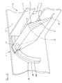
- FIGURE 1 is a schematic perspective view of a valve system incorporating an actuator embodying the present invention, parts of the valve system being shown in cutaway and parts of the actuator being shown in phantom;
- FIGURE 2 is a perspective cross-sectional view of a mid-section of a stator for use with the actuator of Figure 1;
- FIGURE 3 is a plan view of a stator part for use with the actuator of Figure 1;
- FIGURE 4 is a perspective view of the stator part of Figure 3 after a folding step;
- FIGURE 5 is a cross-section through the stator part of Figure 4 along line V-V;
- FIGURE 6 is a partial perspective view of a mid-section of two stator parts shown in Figure 4 interlocked with one another;
- FIGURE 7 is a perspective view of a rotor for use with the actuator of Figure 1;
- FIGURE 8 is a schematic perspective view of an actuator embodying the present invention; and
- FIGURE 9 is a schematic perspective view of another actuator embodying the present invention.
-
- Referring to Figure 1, an
actuator 1 embodying the present invention is shown attached to avalve system 2. Thevalve system 2 is purely an illustration to show one use for the actuator of the present invention. In the present example, thevalve system 2 is part of an air-movingconduit 3. Air flows along theconduit 3 and through anaperture 4 formed in adamper wall 5. Avalve plate 6 is pivotally mounted to theconduit 3 on the downstream side of thedamper wall 5 by a shaft 6A. - The
valve plate 6 is movable between a fully open position which allows the free flow of air through theaperture 4 and a fully closed position in which thevalve plate 6 is sealed to theaperture 4 by aseal 7 provided on thevalve plate 6. - The
actuator 2 comprises two main parts, astator 8 and arotor 9. Thestator 8 is mounted on a fixed platform comprising a side wall of theconduit 3. Therotor 9 is formed as part of thevalve plate 6, i.e. the element to be rotatably actuated. Preferably, thestator 8 is integrated in the conduit wall structure. Thestator 8 androtor 9 are only shown schematically in Figure 1 and are described in greater detail below. - The
stator 8 defines the predetermined limited angle through which the element to be rotated, thevalve plate 6 in this example, may be rotated. Thus, thestator 8 has a predetermined length and a predetermined radius. In the example shown in Figure 1, the limited angle through which thevalve plate 6 is rotatable is substantially 90 degrees. - The
stator 8 is manufactured as a pair of stators 8A,8B only one of which is shown in Figure 2. Eachstator 8 comprises four parts: twostator plates 10 formed from plates of electrical steel to provide a housing for the stator and to provide the stator magnetic poles; a rectangulararcuate core 11; and a winding 12. - Turning firstly to the
stator plates 10, an example of one of these is shown in Figures 3, 4 and 5. Eachstator plate 10 comprises anarcuate strip 13 formed withteeth 14 projecting radially from both the inner radius of thestrip 13 and the outer radius of the strip. Theteeth 14 are evenly spaced along the arcuate length of thestrip 13. The pitch of the teeth in the assembled double stator is twice the step angle. In order to maintain the same number ofteeth 14 on the inner radius of eachstator plate 10 as there are on the outer radius, it is necessary for the teeth on the inner radius to be slightly narrower than the teeth on the outer radius and likewise for the gap between the teeth on the inner radius to be slightly smaller than the gap between the teeth on the outer radius. - As shown in Figure 4, the
teeth 14 are all folded so as to lie at 90 degrees to the plane of theplate 13 thereby defining an arcuate channel having a C-shaped section as shown in Figure 5 which is a section along the line V-V through Figure 4. Twostator plates 10 formed as described above can therefore be interlocked with one another as shown in Figure 2 to form an enclosed channel of rectangular section. - The
core 11 is elongate and arcuate so as to conform to the arcuate profile of thestator plates 10. The core is wound with numerous turns ofwire 12 to produce a wound core which is inserted in the C-section of one of thestator plates 10. Theother stator plate 10 is interlocked with thefirst stator plate 10 to sandwich thewound core - The two pairs of interlocked teeth on the inner radius and outer radius of the
stator 8 comprise two sets of poles for thestator 8. - Two such stators 8A,8B which are substantially identical to one another are fixed adjacent one another as shown in Figure 6 to provide a double stator assembly in the form of an arc. The two stators 8A,8B are staggered or displaced circumferentially with respect to one another by half of one pole pitch as shown in Figure 6 by the phantom centre lines, the two outer centre lines being along the centres of two
teeth 14 in one stator 8A and the inner centre line being along the centre of onetooth 14 in the other stator 8B. - The winding 12 within the stators 8A,8B is controllably energised to provide alternating north and south poles in accordance with a conventional 2 or 4 phase energisation sequence.
- Turning now to the
rotor 9 which is shown in isolation in Figure 7, therotor 9 comprises a pair of spaced apartpermanent magnet blocks 15,16 which are linked by anon-magnetic plate 23 to form a C-section. - The
magnetic blocks 15,16 each comprise an individual rotor. Theblocks 15,16 are spaced apart by a distance which is slightly greater than the radial depth of thestator 8. Thus, anupper block 15 fits alongside the outer radius of thestator 8 and a lower block 16 fits alongside the inner radius of thestator 8 thereby sandwiching thestator 8 between the twoblocks 15,16. Thelower surface 17 of theupper block 15 and theupper surface 18 of the lower block 16 conform to the radius of thestator 8 so that any air gaps between thestator 8 androtor 9 are minimised, thereby avoiding any unnecessary loss of magnetic flux between thestator 8 and therotor 9. - The
inner surfaces rotor 9 radially adjacent thestator 8 are magnetised intostrips 19 of alternate magnetic polarity, i.e. north and south poles. Each pole of therotor 9 runs across the width of therotor 9. It should be noted that the width of therotor 9 is slightly narrower than the combined length of the teeth 14 (of the poles of the stator 8) so that, when the actuator is assembled, the ends of the stator poles protrude slightly past the edges of the rotor. The converse arrangement is also possible. - As shown in Figure 1, the
rotor 9 is formed as part of the element to be moved, in this example as part of thevalve plate 6. Preferably, for torque considerations, therotor 9 is formed at a location which is most distant from the centre of rotation of the element to be rotated (the valve plate 6) so as to provide the greatest moment arm thereby reducing the force requirements of theactuator 1. - The provision of a
rotor 9 having twoparts 15,16 which couple with the stator poles on respective inner and outer radiuses of thestator 8 provides two advantages. Firstly, the torque of the actuator is doubled due to the coupling doubling between the tworotor parts 15,16 and the stator and secondly, the magnetic thrust experienced between the rotor and the stator is substantially cancelled out since substantially opposite thrusts are experienced by the tworotor parts 15,16. Thus, the only resultant force experienced by therotor 9 is substantially radial, as required. - As previously described, the poles of the stator 8 (which comprises a double stator assembly 8A,8B) are formed along the inner and outer radiuses of the
stator 8 so as to allow the poles of therotor 9 to couple with the stator poles on both the inner radius and outer radius of the stator. Thestator 8 androtor 9 are adapted to co-operate with one another, thetop surface 18 of the lower rotor 16 being located immediately radially adjacent the inner radius of thestator 8 and thelower surface 17 of theupper rotor 15 being located immediately radially adjacent the outer radius of thestator 8. Thestrips 19 of the rotor poles being substantially parallel to the teeth 14 (stator poles) on thestator 8. - The
resultant actuator 1, shown in Figure 1 as part of avalve system 2, is therefore configured to operate as a stepper motor, the basic step of the motor being defined by the pitch of thestator poles 14 and rotor magnetic pole pitch. Thus, accurate control of the element to be rotated can be effected by sequential energisation of the winding 12. - A stepper motor driver circuit (not shown) is required to complete the actuator to allow controllable energisation of the stator winding. The provision of such a circuit falls well within the capabilities of a person of ordinary skill in the art of stepper motors. Likewise, variations on the particular configurations of the rotor, the stator, the operation of the actuator and the energisation sequence for the winding are also well within the capabilities of a person of ordinary skill in the art of stepper motors.
- It should be appreciated that the actuator of the present invention is not limited in its application to valve systems but is also of use in general engineering applications where precise rotary control over a limited angle is required.
- In Figure 1, the actuator is shown as being built into the valve and housing assembly. The actuator can, however, be provided as a stand alone unit in its own housing as shown in Figure 8. Only a
back plate 20 of the housing is shown in Figure 8. The basic elements of the actuator are identical to those in the previously described embodiment. Thestator 8 is fixed to the housing backplate 20. Therotor 9 is mounted at one end of anelongate arm 21. The other end of thearm 21 carries ashaft 22. Theshaft 22 is located at the centre of rotation defined by the radius of thestator 8. Actuation of therotor 9 around thestator 8 causes angular movement of thearm 21 and thence rotation of theshaft 22. Rotation of theshaft 22 is limited to the angle defined by thestator 8. The housing can be hermetically sealed to prevent the ingress of dust or other contaminants. - Whilst the stator is described as a double stator assembly, only a single stator is required. The
rotor 9 need not be in the form of a pair ofrotors 15,16 but could comprise just a single rotor block. The rotor block could be located radially adjacent either the inner radius or the outer radius of thestator 8. - The use of a C-section rotor or other form of rotor which serves to sandwich the stator between two rotors (or two
parts 15,16 of the rotor 9) is not restricted to the limited angle rotary actuator described above but can also be used in motors of a more conventional design. - In a variation on the embodiments described above in which the magnetic fields coupling the
rotor 9 andstator 8 together are substantially radially oriented (with respect to the stator radius), embodiments may also be configured in which the coupling magnetic fields are oriented normal to both the radial and tangential directions (with respect to the stator radius). A schematic example of such a configuration is shown in Figure 9, the stator poles being located on the sides of thestator 8 parallel to the radial direction. In this example, therotor parts 15,16 of therotor 9 need not be radiused as required in the embodiment shown in Figure 7.
Claims (15)
- A limited angle rotary actuator comprising:a rotor mountable on an element to be rotated at a position remote from the centre of rotation of the element, the rotor comprising a number of magnetic poles; andan arcuate stator mountable on a platform, the stator being of predetermined length and having a predetermined radius so as to define a limited angle of rotation, the stator having a plurality of poles along its arcuate length which are controllably energisable to alternate their polarity and drive the rotor.
- An actuator according to Claim 1, wherein the rotor comprises a first and a second rotor, the stator being located between the two rotors.
- A rotary actuator comprising:a rotor mountable on an element to be rotated, the rotor comprising a first and a second rotor each provided with a number of magnetic poles; andan arcuate stator mountable on a platform, the stator having a plurality of poles along its arcuate length which are controllably energisable to alternate their polarity and drive the rotor, wherein the stator is located between the first and the second rotors and the stator poles on one side of the stator are adjacent the poles of the first rotor and the stator poles on the other side of the stator are adjacent the poles of the second rotor.
- An actuator according to any preceding claim, wherein the or each rotor comprises a permanent magnet which is magnetised into strips of poles of alternate magnetic polarity.
- An actuator according to any one of Claims 1 to 3, wherein the or each rotor comprises a plurality of discrete permanent magnets having poles of alternate magnetic polarity.
- An actuator according to any preceding claim, wherein the or each rotor is part of an element to be rotated and is located at a position remote from the centre of rotation of the element.
- An actuator according to any preceding claim, wherein the stator is mounted to a fixed platform.
- An actuator according to any preceding claim, wherein the stator is energisable to provide alternating poles in accordance with a conventional 2 or 4 phase energisation sequence.
- An actuator according to any preceding claim, wherein the pitch of the poles of the or each rotor is defined by a desired step angle.
- An actuator according to any preceding claim, wherein the stator has a first set of poles on its inner radius and a second set of poles on its outer radius.
- An actuator according to Claim 10, wherein the poles of the or each respective rotor are located radially adjacent the poles of the stator, the profiles of the stator and the adjacent surface of the or each respective rotor conforming with one another to minimise any air gap.
- An actuator according to any one of Claims 1 to 9, wherein the stator has a first set of poles on one side of the stator, which side extends between the stator inner radius and the stator outer radius, and a second set of poles on an opposite side of the stator, which side extends between the stator inner radius and the stator outer radius.
- An actuator according to Claim 12, wherein the poles of the or each respective rotor are located immediately adjacent the sides of the stator carrying the stator poles, the profiles of the sides of the stator and the adjacent surface of the or each respective rotor conforming with one another to minimise any air gap.
- An actuator according to any preceding claim, wherein the stator comprises a pair of stators.
- An actuator according to any preceding claim, wherein the or each stator comprises an arcuate core provided with a winding and sandwiched between two arcuate stator plates carrying the stator poles.
Priority Applications (5)
| Application Number | Priority Date | Filing Date | Title |
|---|---|---|---|
| AT99305321T ATE266272T1 (en) | 1999-07-05 | 1999-07-05 | ACTUATOR WITH LIMITED ROTATION ANGLE |
| EP99305321A EP1067657B1 (en) | 1999-07-05 | 1999-07-05 | Limited angle rotary actuator |
| DE69917014T DE69917014T2 (en) | 1999-07-05 | 1999-07-05 | Improvements in or relating to rotary actuators |
| US09/608,878 US6507258B1 (en) | 1999-07-05 | 2000-06-30 | Rotary actuators |
| JP2000201034A JP2001320869A (en) | 1999-07-05 | 2000-07-03 | Rotary actuator |
Applications Claiming Priority (1)
| Application Number | Priority Date | Filing Date | Title |
|---|---|---|---|
| EP99305321A EP1067657B1 (en) | 1999-07-05 | 1999-07-05 | Limited angle rotary actuator |
Publications (2)
| Publication Number | Publication Date |
|---|---|
| EP1067657A1 true EP1067657A1 (en) | 2001-01-10 |
| EP1067657B1 EP1067657B1 (en) | 2004-05-06 |
Family
ID=8241501
Family Applications (1)
| Application Number | Title | Priority Date | Filing Date |
|---|---|---|---|
| EP99305321A Expired - Lifetime EP1067657B1 (en) | 1999-07-05 | 1999-07-05 | Limited angle rotary actuator |
Country Status (5)
| Country | Link |
|---|---|
| US (1) | US6507258B1 (en) |
| EP (1) | EP1067657B1 (en) |
| JP (1) | JP2001320869A (en) |
| AT (1) | ATE266272T1 (en) |
| DE (1) | DE69917014T2 (en) |
Cited By (1)
| Publication number | Priority date | Publication date | Assignee | Title |
|---|---|---|---|---|
| WO2009069159A1 (en) * | 2007-11-27 | 2009-06-04 | Massimiliano Zanon | Operating device preferably for machines for controlling and inspecting containers and/or their contents, and corresponding machine |
Families Citing this family (3)
| Publication number | Priority date | Publication date | Assignee | Title |
|---|---|---|---|---|
| CH699897A2 (en) * | 2008-11-10 | 2010-05-14 | Etel Sa | SCARA-type parallel robot. |
| AU2013294616B2 (en) * | 2012-07-26 | 2016-04-28 | Apple Inc. | Dual-axis scanning mirror |
| JP6324384B2 (en) * | 2012-08-31 | 2018-05-16 | リーンテック モーター ゲゼルシャフト ミット ベシュレンクテル ハフツング ウント コンパニー コマンディートゲゼルシャフトLEANTEC Motor GmbH & Co. KG | Electromechanical transducer |
Citations (5)
| Publication number | Priority date | Publication date | Assignee | Title |
|---|---|---|---|---|
| CH384067A (en) * | 1959-09-07 | 1964-11-15 | Elektro Motoren Ag | AC machine |
| JPS58108960A (en) * | 1981-12-22 | 1983-06-29 | Takahashi Yoshiteru | Commutator circular-arc linear motor |
| US4620301A (en) * | 1982-12-20 | 1986-10-28 | Ricoh Company, Ltd. | Recording disk drive unit |
| JPS63310361A (en) * | 1987-06-12 | 1988-12-19 | Tokyo Electric Co Ltd | Linear pulse motor |
| DE9214383U1 (en) * | 1992-10-23 | 1994-02-24 | Intrasys Gmbh | Linear motor |
Family Cites Families (24)
| Publication number | Priority date | Publication date | Assignee | Title |
|---|---|---|---|---|
| DE384067C (en) | 1919-07-25 | 1923-10-20 | Werner & Pfleiderer | Process for the production of high quality fondant chocolate and similar types of chocolate |
| DE2451876B2 (en) * | 1974-10-31 | 1978-04-27 | Agfa-Gevaert Ag, 5090 Leverkusen | Synchronous motor, especially stepper motor |
| CA1266877A (en) * | 1984-09-13 | 1990-03-20 | Erich Rabe | Electronically commutated dc machine and use thereof |
| US4810914A (en) * | 1987-03-26 | 1989-03-07 | International Business Machines Corporation | Linear actuator with multiple closed loop flux paths essentially orthogonal to its axis |
| JPH0193979U (en) * | 1987-12-15 | 1989-06-21 | ||
| US4837474A (en) * | 1988-08-12 | 1989-06-06 | Camatec Corporation | D.C. motor |
| US5041935A (en) * | 1988-08-17 | 1991-08-20 | Fujitsu Limited | Rotary actuator for positioning magnetic heads in a disk drive |
| ES2045145T3 (en) * | 1988-11-07 | 1994-01-16 | Cornelius Alewyn Jo Kritzinger | ELECTRIC MACHINES |
| JPH07118901B2 (en) * | 1990-04-28 | 1995-12-18 | いすゞ自動車株式会社 | Eddy current type speed reducer |
| US5038066A (en) * | 1990-09-12 | 1991-08-06 | General Motors Corporation | Claw pole rotary actuator with limited angular movement |
| JPH07113395B2 (en) * | 1991-04-01 | 1995-12-06 | 科学技術庁航空宇宙技術研究所長 | Multi-dimensional damper device |
| US5245238A (en) * | 1991-04-30 | 1993-09-14 | Sundstrand Corporation | Axial gap dual permanent magnet generator |
| US5334899A (en) * | 1991-09-30 | 1994-08-02 | Dymytro Skybyk | Polyphase brushless DC and AC synchronous machines |
| US5448117A (en) * | 1993-02-25 | 1995-09-05 | Consulier Engineering, Inc. | Stepper motor |
| US5677581A (en) * | 1994-06-16 | 1997-10-14 | Nippondenso Co., Ltd. | Stepping motor with protruding pole teeth to increase detent torque |
| GB2290911A (en) * | 1994-06-28 | 1996-01-10 | Dafydd Roberts | Rotary electromagnetic actuator |
| US6060800A (en) * | 1995-07-12 | 2000-05-09 | Minebea Co., Ltd. | Motor structure |
| FR2742939B1 (en) * | 1995-12-21 | 1998-03-06 | Jeumont Ind | MODULAR DISCOID ELECTRIC MACHINE |
| JPH1042542A (en) * | 1996-07-26 | 1998-02-13 | Nippon Seiki Co Ltd | Stepping motor |
| US5910697A (en) * | 1997-01-17 | 1999-06-08 | Samon Engineering Ltd. | High-power, low-voltage axial air-gap electrical machine having a compact stator |
| JP3131403B2 (en) * | 1997-04-07 | 2001-01-31 | 日本サーボ株式会社 | Stepping motor |
| DE19818035A1 (en) * | 1998-04-22 | 1999-10-28 | Bayerische Motoren Werke Ag | Transverse flux machine |
| US6198182B1 (en) * | 1998-09-02 | 2001-03-06 | Cts Corporation | Two-phase stepper motor having two disk stators with salient poles positioned on either side of two disk rotors |
| US6049149A (en) * | 1999-03-23 | 2000-04-11 | Lin; Shou-Mei | Brushless DC motor having opposed pairs of axial magnetic field type permanent magnets and control system therefor |
-
1999
- 1999-07-05 DE DE69917014T patent/DE69917014T2/en not_active Expired - Fee Related
- 1999-07-05 AT AT99305321T patent/ATE266272T1/en not_active IP Right Cessation
- 1999-07-05 EP EP99305321A patent/EP1067657B1/en not_active Expired - Lifetime
-
2000
- 2000-06-30 US US09/608,878 patent/US6507258B1/en not_active Expired - Fee Related
- 2000-07-03 JP JP2000201034A patent/JP2001320869A/en not_active Withdrawn
Patent Citations (5)
| Publication number | Priority date | Publication date | Assignee | Title |
|---|---|---|---|---|
| CH384067A (en) * | 1959-09-07 | 1964-11-15 | Elektro Motoren Ag | AC machine |
| JPS58108960A (en) * | 1981-12-22 | 1983-06-29 | Takahashi Yoshiteru | Commutator circular-arc linear motor |
| US4620301A (en) * | 1982-12-20 | 1986-10-28 | Ricoh Company, Ltd. | Recording disk drive unit |
| JPS63310361A (en) * | 1987-06-12 | 1988-12-19 | Tokyo Electric Co Ltd | Linear pulse motor |
| DE9214383U1 (en) * | 1992-10-23 | 1994-02-24 | Intrasys Gmbh | Linear motor |
Non-Patent Citations (2)
| Title |
|---|
| PATENT ABSTRACTS OF JAPAN vol. 007, no. 218 (E - 200) 28 September 1983 (1983-09-28) * |
| PATENT ABSTRACTS OF JAPAN vol. 013, no. 150 (E - 742) 12 April 1989 (1989-04-12) * |
Cited By (3)
| Publication number | Priority date | Publication date | Assignee | Title |
|---|---|---|---|---|
| WO2009069159A1 (en) * | 2007-11-27 | 2009-06-04 | Massimiliano Zanon | Operating device preferably for machines for controlling and inspecting containers and/or their contents, and corresponding machine |
| EA016121B1 (en) * | 2007-11-27 | 2012-02-28 | Массимилиано Дзанон | Operating device preferably for machines for controlling and inspecting containers and/or their contents, and corresponding machine |
| US8508163B2 (en) | 2007-11-27 | 2013-08-13 | Massimiliano Zanon | Operating device preferably for machines for controlling and inspecting containers and/or their contents, and corresponding machine |
Also Published As
| Publication number | Publication date |
|---|---|
| DE69917014T2 (en) | 2005-04-28 |
| DE69917014D1 (en) | 2004-06-09 |
| US6507258B1 (en) | 2003-01-14 |
| JP2001320869A (en) | 2001-11-16 |
| ATE266272T1 (en) | 2004-05-15 |
| EP1067657B1 (en) | 2004-05-06 |
Similar Documents
| Publication | Publication Date | Title |
|---|---|---|
| US4680494A (en) | Multiphase motor with facially magnetized rotor having N/2 pairs of poles per face | |
| KR102598034B1 (en) | Compact motor reducer | |
| US5093596A (en) | Combined linear-rotary direct drive step motor | |
| US4899072A (en) | Pulse motor | |
| US4634906A (en) | Multiphase motor with magnetized rotor having N pairs of poles with axial magnetization | |
| US6198182B1 (en) | Two-phase stepper motor having two disk stators with salient poles positioned on either side of two disk rotors | |
| KR20100014886A (en) | Nested variable field dynamoelectric machine | |
| WO2007095254A1 (en) | Electric motor with field weakening | |
| US5982058A (en) | Two-phase stepper motor | |
| CA2553795C (en) | Eccentric screw pump with integrated drive | |
| KR0144316B1 (en) | Linear pulse motor | |
| WO1982002619A1 (en) | Electric motors | |
| EP3032727B1 (en) | Reluctance motor with virtual rotor | |
| US7994672B2 (en) | Limited angle external rotor motor actuator system | |
| JP5513174B2 (en) | Geared motor | |
| CN109417333A (en) | Electric system | |
| US4792709A (en) | Winding for operation of a three-phase stepping motor from a two-phase drive | |
| KR0142518B1 (en) | Linear pulse motor | |
| US6507258B1 (en) | Rotary actuators | |
| KR0164889B1 (en) | Method of manufacturing an iron core of a multi-phase linear motor | |
| JP4061835B2 (en) | Electric motor | |
| EP0729218A2 (en) | Actuator | |
| US20140152129A1 (en) | Double rotor stepping motor | |
| JPH038076Y2 (en) | ||
| EP0600110A1 (en) | Magnetic speed reducer |
Legal Events
| Date | Code | Title | Description |
|---|---|---|---|
| PUAI | Public reference made under article 153(3) epc to a published international application that has entered the european phase |
Free format text: ORIGINAL CODE: 0009012 |
|
| AK | Designated contracting states |
Kind code of ref document: A1 Designated state(s): AT BE CH CY DE DK ES FI FR GB GR IE IT LI LU MC NL PT SE |
|
| AX | Request for extension of the european patent |
Free format text: AL;LT;LV;MK;RO;SI |
|
| 17P | Request for examination filed |
Effective date: 20010606 |
|
| AKX | Designation fees paid |
Free format text: AT BE CH CY DE DK ES FI FR GB GR IE IT LI LU MC NL PT SE |
|
| 17Q | First examination report despatched |
Effective date: 20011106 |
|
| RAP1 | Party data changed (applicant data changed or rights of an application transferred) |
Owner name: MINEBEA CO., LTD. |
|
| GRAP | Despatch of communication of intention to grant a patent |
Free format text: ORIGINAL CODE: EPIDOSNIGR1 |
|
| RIC1 | Information provided on ipc code assigned before grant |
Ipc: 7H 02K 37/12 B Ipc: 7H 02K 41/03 A |
|
| GRAS | Grant fee paid |
Free format text: ORIGINAL CODE: EPIDOSNIGR3 |
|
| GRAA | (expected) grant |
Free format text: ORIGINAL CODE: 0009210 |
|
| AK | Designated contracting states |
Kind code of ref document: B1 Designated state(s): AT BE CH CY DE DK ES FI FR GB GR IE IT LI LU MC NL PT SE |
|
| PG25 | Lapsed in a contracting state [announced via postgrant information from national office to epo] |
Ref country code: NL Free format text: LAPSE BECAUSE OF FAILURE TO SUBMIT A TRANSLATION OF THE DESCRIPTION OR TO PAY THE FEE WITHIN THE PRESCRIBED TIME-LIMIT Effective date: 20040506 Ref country code: LI Free format text: LAPSE BECAUSE OF FAILURE TO SUBMIT A TRANSLATION OF THE DESCRIPTION OR TO PAY THE FEE WITHIN THE PRESCRIBED TIME-LIMIT Effective date: 20040506 Ref country code: FI Free format text: LAPSE BECAUSE OF FAILURE TO SUBMIT A TRANSLATION OF THE DESCRIPTION OR TO PAY THE FEE WITHIN THE PRESCRIBED TIME-LIMIT Effective date: 20040506 Ref country code: CY Free format text: LAPSE BECAUSE OF FAILURE TO SUBMIT A TRANSLATION OF THE DESCRIPTION OR TO PAY THE FEE WITHIN THE PRESCRIBED TIME-LIMIT Effective date: 20040506 Ref country code: CH Free format text: LAPSE BECAUSE OF FAILURE TO SUBMIT A TRANSLATION OF THE DESCRIPTION OR TO PAY THE FEE WITHIN THE PRESCRIBED TIME-LIMIT Effective date: 20040506 Ref country code: BE Free format text: LAPSE BECAUSE OF FAILURE TO SUBMIT A TRANSLATION OF THE DESCRIPTION OR TO PAY THE FEE WITHIN THE PRESCRIBED TIME-LIMIT Effective date: 20040506 Ref country code: AT Free format text: LAPSE BECAUSE OF FAILURE TO SUBMIT A TRANSLATION OF THE DESCRIPTION OR TO PAY THE FEE WITHIN THE PRESCRIBED TIME-LIMIT Effective date: 20040506 |
|
| REG | Reference to a national code |
Ref country code: GB Ref legal event code: FG4D |
|
| REG | Reference to a national code |
Ref country code: CH Ref legal event code: EP |
|
| REF | Corresponds to: |
Ref document number: 69917014 Country of ref document: DE Date of ref document: 20040609 Kind code of ref document: P |
|
| REG | Reference to a national code |
Ref country code: IE Ref legal event code: FG4D |
|
| PG25 | Lapsed in a contracting state [announced via postgrant information from national office to epo] |
Ref country code: LU Free format text: LAPSE BECAUSE OF NON-PAYMENT OF DUE FEES Effective date: 20040705 Ref country code: IE Free format text: LAPSE BECAUSE OF NON-PAYMENT OF DUE FEES Effective date: 20040705 |
|
| PG25 | Lapsed in a contracting state [announced via postgrant information from national office to epo] |
Ref country code: MC Free format text: LAPSE BECAUSE OF NON-PAYMENT OF DUE FEES Effective date: 20040731 |
|
| PG25 | Lapsed in a contracting state [announced via postgrant information from national office to epo] |
Ref country code: SE Free format text: LAPSE BECAUSE OF FAILURE TO SUBMIT A TRANSLATION OF THE DESCRIPTION OR TO PAY THE FEE WITHIN THE PRESCRIBED TIME-LIMIT Effective date: 20040806 Ref country code: GR Free format text: LAPSE BECAUSE OF FAILURE TO SUBMIT A TRANSLATION OF THE DESCRIPTION OR TO PAY THE FEE WITHIN THE PRESCRIBED TIME-LIMIT Effective date: 20040806 Ref country code: DK Free format text: LAPSE BECAUSE OF FAILURE TO SUBMIT A TRANSLATION OF THE DESCRIPTION OR TO PAY THE FEE WITHIN THE PRESCRIBED TIME-LIMIT Effective date: 20040806 |
|
| PG25 | Lapsed in a contracting state [announced via postgrant information from national office to epo] |
Ref country code: ES Free format text: LAPSE BECAUSE OF FAILURE TO SUBMIT A TRANSLATION OF THE DESCRIPTION OR TO PAY THE FEE WITHIN THE PRESCRIBED TIME-LIMIT Effective date: 20040817 |
|
| NLV1 | Nl: lapsed or annulled due to failure to fulfill the requirements of art. 29p and 29m of the patents act | ||
| REG | Reference to a national code |
Ref country code: CH Ref legal event code: PL |
|
| ET | Fr: translation filed | ||
| PLBE | No opposition filed within time limit |
Free format text: ORIGINAL CODE: 0009261 |
|
| STAA | Information on the status of an ep patent application or granted ep patent |
Free format text: STATUS: NO OPPOSITION FILED WITHIN TIME LIMIT |
|
| REG | Reference to a national code |
Ref country code: IE Ref legal event code: MM4A |
|
| 26N | No opposition filed |
Effective date: 20050208 |
|
| PGFP | Annual fee paid to national office [announced via postgrant information from national office to epo] |
Ref country code: DE Payment date: 20050630 Year of fee payment: 7 |
|
| PGFP | Annual fee paid to national office [announced via postgrant information from national office to epo] |
Ref country code: FR Payment date: 20050708 Year of fee payment: 7 |
|
| PGFP | Annual fee paid to national office [announced via postgrant information from national office to epo] |
Ref country code: IT Payment date: 20060731 Year of fee payment: 8 |
|
| PG25 | Lapsed in a contracting state [announced via postgrant information from national office to epo] |
Ref country code: DE Free format text: LAPSE BECAUSE OF NON-PAYMENT OF DUE FEES Effective date: 20070201 |
|
| REG | Reference to a national code |
Ref country code: FR Ref legal event code: ST Effective date: 20070330 |
|
| PG25 | Lapsed in a contracting state [announced via postgrant information from national office to epo] |
Ref country code: PT Free format text: LAPSE BECAUSE OF NON-PAYMENT OF DUE FEES Effective date: 20041006 |
|
| PG25 | Lapsed in a contracting state [announced via postgrant information from national office to epo] |
Ref country code: FR Free format text: LAPSE BECAUSE OF NON-PAYMENT OF DUE FEES Effective date: 20060731 |
|
| PGFP | Annual fee paid to national office [announced via postgrant information from national office to epo] |
Ref country code: GB Payment date: 20080709 Year of fee payment: 10 |
|
| PG25 | Lapsed in a contracting state [announced via postgrant information from national office to epo] |
Ref country code: IT Free format text: LAPSE BECAUSE OF NON-PAYMENT OF DUE FEES Effective date: 20070705 |
|
| GBPC | Gb: european patent ceased through non-payment of renewal fee |
Effective date: 20090705 |
|
| PG25 | Lapsed in a contracting state [announced via postgrant information from national office to epo] |
Ref country code: GB Free format text: LAPSE BECAUSE OF NON-PAYMENT OF DUE FEES Effective date: 20090705 |