EP1067639A1 - Instabiler Laserresonator - Google Patents
Instabiler Laserresonator Download PDFInfo
- Publication number
- EP1067639A1 EP1067639A1 EP00401916A EP00401916A EP1067639A1 EP 1067639 A1 EP1067639 A1 EP 1067639A1 EP 00401916 A EP00401916 A EP 00401916A EP 00401916 A EP00401916 A EP 00401916A EP 1067639 A1 EP1067639 A1 EP 1067639A1
- Authority
- EP
- European Patent Office
- Prior art keywords
- cavity
- optical
- prisms
- laser
- unstable
- Prior art date
- Legal status (The legal status is an assumption and is not a legal conclusion. Google has not performed a legal analysis and makes no representation as to the accuracy of the status listed.)
- Withdrawn
Links
- 230000003287 optical effect Effects 0.000 claims abstract description 46
- PCTMTFRHKVHKIS-BMFZQQSSSA-N (1s,3r,4e,6e,8e,10e,12e,14e,16e,18s,19r,20r,21s,25r,27r,30r,31r,33s,35r,37s,38r)-3-[(2r,3s,4s,5s,6r)-4-amino-3,5-dihydroxy-6-methyloxan-2-yl]oxy-19,25,27,30,31,33,35,37-octahydroxy-18,20,21-trimethyl-23-oxo-22,39-dioxabicyclo[33.3.1]nonatriaconta-4,6,8,10 Chemical compound C1C=C2C[C@@H](OS(O)(=O)=O)CC[C@]2(C)[C@@H]2[C@@H]1[C@@H]1CC[C@H]([C@H](C)CCCC(C)C)[C@@]1(C)CC2.O[C@H]1[C@@H](N)[C@H](O)[C@@H](C)O[C@H]1O[C@H]1/C=C/C=C/C=C/C=C/C=C/C=C/C=C/[C@H](C)[C@@H](O)[C@@H](C)[C@H](C)OC(=O)C[C@H](O)C[C@H](O)CC[C@@H](O)[C@H](O)C[C@H](O)C[C@](O)(C[C@H](O)[C@H]2C(O)=O)O[C@H]2C1 PCTMTFRHKVHKIS-BMFZQQSSSA-N 0.000 claims abstract description 4
- 239000011521 glass Substances 0.000 claims abstract description 4
- 230000008878 coupling Effects 0.000 claims description 9
- 238000010168 coupling process Methods 0.000 claims description 9
- 238000005859 coupling reaction Methods 0.000 claims description 9
- 239000000463 material Substances 0.000 claims description 5
- 239000013078 crystal Substances 0.000 claims description 4
- 238000005086 pumping Methods 0.000 claims description 3
- 210000000887 face Anatomy 0.000 description 10
- 238000010586 diagram Methods 0.000 description 6
- 238000011282 treatment Methods 0.000 description 3
- 101100536354 Drosophila melanogaster tant gene Proteins 0.000 description 2
- 229910052779 Neodymium Inorganic materials 0.000 description 1
- 239000011149 active material Substances 0.000 description 1
- 230000003667 anti-reflective effect Effects 0.000 description 1
- 239000000470 constituent Substances 0.000 description 1
- 230000000694 effects Effects 0.000 description 1
- 230000004907 flux Effects 0.000 description 1
- 239000002223 garnet Substances 0.000 description 1
- 230000012447 hatching Effects 0.000 description 1
- 210000003128 head Anatomy 0.000 description 1
- 230000004048 modification Effects 0.000 description 1
- 238000012986 modification Methods 0.000 description 1
- QEFYFXOXNSNQGX-UHFFFAOYSA-N neodymium atom Chemical compound [Nd] QEFYFXOXNSNQGX-UHFFFAOYSA-N 0.000 description 1
- 210000001747 pupil Anatomy 0.000 description 1
- 229910052727 yttrium Inorganic materials 0.000 description 1
- VWQVUPCCIRVNHF-UHFFFAOYSA-N yttrium atom Chemical compound [Y] VWQVUPCCIRVNHF-UHFFFAOYSA-N 0.000 description 1
Images

Classifications
-
- H—ELECTRICITY
- H01—ELECTRIC ELEMENTS
- H01S—DEVICES USING THE PROCESS OF LIGHT AMPLIFICATION BY STIMULATED EMISSION OF RADIATION [LASER] TO AMPLIFY OR GENERATE LIGHT; DEVICES USING STIMULATED EMISSION OF ELECTROMAGNETIC RADIATION IN WAVE RANGES OTHER THAN OPTICAL
- H01S3/00—Lasers, i.e. devices using stimulated emission of electromagnetic radiation in the infrared, visible or ultraviolet wave range
- H01S3/05—Construction or shape of optical resonators; Accommodation of active medium therein; Shape of active medium
- H01S3/08—Construction or shape of optical resonators or components thereof
- H01S3/081—Construction or shape of optical resonators or components thereof comprising three or more reflectors
- H01S3/0818—Unstable resonators
-
- G—PHYSICS
- G02—OPTICS
- G02F—OPTICAL DEVICES OR ARRANGEMENTS FOR THE CONTROL OF LIGHT BY MODIFICATION OF THE OPTICAL PROPERTIES OF THE MEDIA OF THE ELEMENTS INVOLVED THEREIN; NON-LINEAR OPTICS; FREQUENCY-CHANGING OF LIGHT; OPTICAL LOGIC ELEMENTS; OPTICAL ANALOGUE/DIGITAL CONVERTERS
- G02F1/00—Devices or arrangements for the control of the intensity, colour, phase, polarisation or direction of light arriving from an independent light source, e.g. switching, gating or modulating; Non-linear optics
- G02F1/35—Non-linear optics
- G02F1/39—Non-linear optics for parametric generation or amplification of light, infrared or ultraviolet waves
-
- H—ELECTRICITY
- H01—ELECTRIC ELEMENTS
- H01S—DEVICES USING THE PROCESS OF LIGHT AMPLIFICATION BY STIMULATED EMISSION OF RADIATION [LASER] TO AMPLIFY OR GENERATE LIGHT; DEVICES USING STIMULATED EMISSION OF ELECTROMAGNETIC RADIATION IN WAVE RANGES OTHER THAN OPTICAL
- H01S3/00—Lasers, i.e. devices using stimulated emission of electromagnetic radiation in the infrared, visible or ultraviolet wave range
- H01S3/005—Optical devices external to the laser cavity, specially adapted for lasers, e.g. for homogenisation of the beam or for manipulating laser pulses, e.g. pulse shaping
- H01S3/0092—Nonlinear frequency conversion, e.g. second harmonic generation [SHG] or sum- or difference-frequency generation outside the laser cavity
-
- H—ELECTRICITY
- H01—ELECTRIC ELEMENTS
- H01S—DEVICES USING THE PROCESS OF LIGHT AMPLIFICATION BY STIMULATED EMISSION OF RADIATION [LASER] TO AMPLIFY OR GENERATE LIGHT; DEVICES USING STIMULATED EMISSION OF ELECTROMAGNETIC RADIATION IN WAVE RANGES OTHER THAN OPTICAL
- H01S3/00—Lasers, i.e. devices using stimulated emission of electromagnetic radiation in the infrared, visible or ultraviolet wave range
- H01S3/05—Construction or shape of optical resonators; Accommodation of active medium therein; Shape of active medium
- H01S3/06—Construction or shape of active medium
- H01S3/0602—Crystal lasers or glass lasers
- H01S3/0606—Crystal lasers or glass lasers with polygonal cross-section, e.g. slab, prism
-
- H—ELECTRICITY
- H01—ELECTRIC ELEMENTS
- H01S—DEVICES USING THE PROCESS OF LIGHT AMPLIFICATION BY STIMULATED EMISSION OF RADIATION [LASER] TO AMPLIFY OR GENERATE LIGHT; DEVICES USING STIMULATED EMISSION OF ELECTROMAGNETIC RADIATION IN WAVE RANGES OTHER THAN OPTICAL
- H01S3/00—Lasers, i.e. devices using stimulated emission of electromagnetic radiation in the infrared, visible or ultraviolet wave range
- H01S3/05—Construction or shape of optical resonators; Accommodation of active medium therein; Shape of active medium
- H01S3/06—Construction or shape of active medium
- H01S3/07—Construction or shape of active medium consisting of a plurality of parts, e.g. segments
-
- H—ELECTRICITY
- H01—ELECTRIC ELEMENTS
- H01S—DEVICES USING THE PROCESS OF LIGHT AMPLIFICATION BY STIMULATED EMISSION OF RADIATION [LASER] TO AMPLIFY OR GENERATE LIGHT; DEVICES USING STIMULATED EMISSION OF ELECTROMAGNETIC RADIATION IN WAVE RANGES OTHER THAN OPTICAL
- H01S3/00—Lasers, i.e. devices using stimulated emission of electromagnetic radiation in the infrared, visible or ultraviolet wave range
- H01S3/05—Construction or shape of optical resonators; Accommodation of active medium therein; Shape of active medium
- H01S3/08—Construction or shape of optical resonators or components thereof
- H01S3/08054—Passive cavity elements acting on the polarization, e.g. a polarizer for branching or walk-off compensation
-
- H—ELECTRICITY
- H01—ELECTRIC ELEMENTS
- H01S—DEVICES USING THE PROCESS OF LIGHT AMPLIFICATION BY STIMULATED EMISSION OF RADIATION [LASER] TO AMPLIFY OR GENERATE LIGHT; DEVICES USING STIMULATED EMISSION OF ELECTROMAGNETIC RADIATION IN WAVE RANGES OTHER THAN OPTICAL
- H01S3/00—Lasers, i.e. devices using stimulated emission of electromagnetic radiation in the infrared, visible or ultraviolet wave range
- H01S3/05—Construction or shape of optical resonators; Accommodation of active medium therein; Shape of active medium
- H01S3/08—Construction or shape of optical resonators or components thereof
- H01S3/08059—Constructional details of the reflector, e.g. shape
-
- H—ELECTRICITY
- H01—ELECTRIC ELEMENTS
- H01S—DEVICES USING THE PROCESS OF LIGHT AMPLIFICATION BY STIMULATED EMISSION OF RADIATION [LASER] TO AMPLIFY OR GENERATE LIGHT; DEVICES USING STIMULATED EMISSION OF ELECTROMAGNETIC RADIATION IN WAVE RANGES OTHER THAN OPTICAL
- H01S3/00—Lasers, i.e. devices using stimulated emission of electromagnetic radiation in the infrared, visible or ultraviolet wave range
- H01S3/05—Construction or shape of optical resonators; Accommodation of active medium therein; Shape of active medium
- H01S3/08—Construction or shape of optical resonators or components thereof
- H01S3/081—Construction or shape of optical resonators or components thereof comprising three or more reflectors
- H01S3/083—Ring lasers
-
- H—ELECTRICITY
- H01—ELECTRIC ELEMENTS
- H01S—DEVICES USING THE PROCESS OF LIGHT AMPLIFICATION BY STIMULATED EMISSION OF RADIATION [LASER] TO AMPLIFY OR GENERATE LIGHT; DEVICES USING STIMULATED EMISSION OF ELECTROMAGNETIC RADIATION IN WAVE RANGES OTHER THAN OPTICAL
- H01S3/00—Lasers, i.e. devices using stimulated emission of electromagnetic radiation in the infrared, visible or ultraviolet wave range
- H01S3/09—Processes or apparatus for excitation, e.g. pumping
- H01S3/091—Processes or apparatus for excitation, e.g. pumping using optical pumping
- H01S3/094—Processes or apparatus for excitation, e.g. pumping using optical pumping by coherent light
- H01S3/0941—Processes or apparatus for excitation, e.g. pumping using optical pumping by coherent light of a laser diode
- H01S3/09415—Processes or apparatus for excitation, e.g. pumping using optical pumping by coherent light of a laser diode the pumping beam being parallel to the lasing mode of the pumped medium, e.g. end-pumping
-
- H—ELECTRICITY
- H01—ELECTRIC ELEMENTS
- H01S—DEVICES USING THE PROCESS OF LIGHT AMPLIFICATION BY STIMULATED EMISSION OF RADIATION [LASER] TO AMPLIFY OR GENERATE LIGHT; DEVICES USING STIMULATED EMISSION OF ELECTROMAGNETIC RADIATION IN WAVE RANGES OTHER THAN OPTICAL
- H01S3/00—Lasers, i.e. devices using stimulated emission of electromagnetic radiation in the infrared, visible or ultraviolet wave range
- H01S3/10—Controlling the intensity, frequency, phase, polarisation or direction of the emitted radiation, e.g. switching, gating, modulating or demodulating
- H01S3/11—Mode locking; Q-switching; Other giant-pulse techniques, e.g. cavity dumping
- H01S3/1123—Q-switching
Definitions
- the present invention relates to unstable optical cavities for laser beam, used in particular in the field of laser cavities and optical parametric oscillators.
- These cavities are said to be unstable because a light ray circulating in these cavities moves away from the optical axis as it spread.
- the outer part of the beam circulating in the cavity is voluntarily transmitted out of the cavity by an exit mirror provided for this effect; this outer part constitutes the useful beam.
- the mirrors used in known optical cavities have a limited flow resistance; indeed the luminous flux which circulates in these cavities has tendency to deteriorate the multi-electric treatments of the mirrors which ensure changes of direction.
- the object of the present invention is to avoid this drawback.
- an unstable optical cavity for laser beam, in which a beam is created, this cavity having a optical path called a ring, with n, where n is an integer greater than 2, changes of direction to make the ring and comprising, in the path optical, an optical assembly of magnification, n deflection means for subject the beam created in the cavity to the n changes of direction, and an outlet, characterized in that the deflection means are n prisms each of which has an interface, called a reflective interface, of the air-glass type which ensures a change of direction by total reflection and in that n-1 of the prisms, called large prisms, have their interface reflective of sufficient size to reflect, in the cavity, the entire beam while one of the prisms, called the output prism, is placed at the output level and has a reflective interface of insufficient size to reflect, in the cavity, the entire beam created in the cavity.
- the deflection means are n prisms each of which has an interface, called a reflective interface, of the air-glass type which ensures
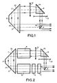
- Figure 1 is a sectional view of an unstable type cavity; this cavity has a ring optical path, ABCD, shown in lines axes; it should be noted that the optical path is in the form of a rectangle in the example described and that the optical paths in rings are, in reality, convex polygons.
- Figure 1 are shown only the elements which help guide a laser beam into the cavity; the other elements, such as in particular that those who produce this laser beam have not been drawn to make the drawing clearer and to facilitate the explanation and understanding of the invention.
- the cavity according to FIG. 1 comprises four prisms Ps, P1 to P3 with each one of their faces used in total reflection; the faces used in total reflection are respectively arranged in the four vertices of rectangle ABCD.
- the cavity also includes a set magnification optic consisting of a divergent lens Ld and a converging lens Lc respectively arranged in the sections AB and BC of the ring.
- prisms P2 and P3 are grouped into one optical unit, K, in the example described but could also be distinct from each other as it will appear in the embodiment according to the figure 7.
- the edge of the laser beam has been drawn in thin lines with arrowheads showing the direction of light propagation.
- the four Ps prisms, P1 to P3 are section prisms in isosceles right triangle shape; their faces whose trace on figure 1 constitutes the two sides of the isosceles triangle, respectively serve as a face input and output face; their face, the trace of which in FIG. 1 constitutes the isosceles right triangle hypotenuse is the one used in total reflection.
- the prisms P2, P3 are grouped together in the optical unit K, the exit face of the prism P2 and the entry face of the prism P3 are virtual faces but everything happens, optically, as if they existed and formed two parallel faces separated by a blade with parallel faces made of the same material as the prisms.
- the Ld-Lc magnification assembly is arranged on both sides of the prism P1: the divergent lens Ld transforms the ray laser beam parallels, coming from the prism Ps, in a divergent beam which is deflected at right angles by the prism P1, then the converging lens Lc transforms the divergent laser beam into a beam with parallel rays; the magnification is equal to the ratio of the focal lengths of the lens Lc over the Ld lens.
- the Ld-Lc magnification set could be arranged differently in the optical path inside the cavity, for example between lenses P1 and P2 or P3 and Ps.
- the laser beam be with parallel rays when it arrives at the level of the prism Ps, since it is part of this beam which leaves the cavity at the level of the output prism that constitutes the Ps prism.
- the output prism Ps unlike the prisms P1 to P3, is insufficient in size to reflect, in the cavity, the entire laser beam which arrives at its level; the prism Ps thus plays the role of pupil and determines the section of the laser beam in the cavity; only the light it reflects is recycled in the cavity, that which passes around the prism Ps constitutes the beam of exit from the cavity; it has been identified by hatching in Figure 1. Possibly, if the beam was divergent at the exit of the cavity, it could be transformed into a beam with parallel rays, for example at by means of a converging lens.
- FIG 2 shows, in section, the cavity according to Figure 1 in an example of use as a laser cavity.
- a laser head with diodes, M is inserted between the lens converging Lc and the prism P2 while, between the prism P3 and the prism Ps, are successively arranged a laser head with diodes, N, a trigger device, Q, called Q-switch in Anglo-Saxon literature and a rotator from Faraday, R.
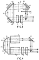
- Figure 3 relates to a variant of the laser cavity according to the figure 2.
- the laser heads M, N are replaced by heads laser associated with prisms P1 to P3: the prism P1 and the optical unit K are made of active material i.e. laser material also called amplifier material which in the example described is Yttrium Garnet doped Neodymium, known under the reference Nd: YAG; to mark the difference between the materials used in the embodiments according to figures 2 and 3, the references P1, K, P2, P3 have been replaced by P1I, K1, P2I, P3I; laser pumping is carried out at the faces of reflection of the prisms P1I, P2I and P3I, respectively by three bars of laser diodes E1, E2 and E3.
- a trigger, Q, and a Faraday rotator, R are arranged in series between prisms P3 and Ps.
- FIG. 4 relates to another variant of the laser cavity according to the Figure 2; according to this variant the flat faces used as reflectors in the prisms P1 and P2 are replaced by spherical faces for constitute respectively a convex reflector Fd and a concave reflector Fc; these two reflectors constitute an optical assembly of magnification which replaces the lenses Ld, Lc of the embodiment according to FIG. 2.
- the elements M, N, Q, R of figure 2 are also present on figure 4.
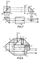
- Figures 5 to 8 are sectional views showing how the unstable cavity according to Figure 1 can be used to make optical parametric oscillators or O.P.O. which constitute sources laser with adjustable wavelength; the fact that the cavity according to Figure 1 can operate over a wide range of wavelengths so here takes all his importance.
- the O.P.O. present an implementation constraint that does not exist not in the laser cavities, namely the coupling of a pump beam, Fp, in the cavity.
- Figures 5 to 7 are three diagrams which illustrate three different ways to perform this coupling of the pump harness.
- a dichroic blade, G is inserted between the converging lens Lc and the prism P2; this blade, inclined at 45 degrees to the BC section, is transparent to the laser beam in the cavity and reflective for the pump beam.
- the O.P.O. includes a non-linear crystal, H, inserted in the section CA and which constitutes the laser medium of the O.P.O.
- the embodiment according to Figure 6 corresponds to that according to Figure 5 with the difference that, instead of the dichroic blade G, is a polarizing prism G '; of course it is necessary in this case, that the beam pump is polarized perpendicular to the beam created in the cavity.
- the embodiment according to FIG. 7 is a variant to that according to the Figure 6.
- the polarizing prism G ' is removed and the optical unit K is replaced by two separate prisms, P2g and P3.
- the P2g prism is a prism polarizer which plays a double role: ensuring the coupling of the beam pump, Fp, in the cavity and cause a deflection of the beam created in the cavity; again the pump harness must be polarized perpendicular to the beam created in the cavity.
- the beam created in the cavity is reflected by the separating surface of the polarizing prism and the part of the P2g prism through which the beam is created in the cavity corresponds to the prism P2 of the optical unit K of FIGS. 5 and 6; as for the pump beam it crosses, without being deflected, the prism P2g.
- FIGS. 2 to 7 can be produced under compact shape as shown in Figure 8 which is a sectional view; sure this figure appears in more detail how are assembled different elements of the O.P.O. in Figure 6.
- the successive elements Ld, P1, Lc, G ', K, H, Ps are joined and the prism of Ps output consists of an optical unit designed to facilitate assembly; this optical unit corresponds to the prism Ps of FIG. 6 on the two faces orthogonal of which would have been pressed respectively two blades to parallel faces.
- the present invention is not limited to the examples described where mentioned this is how, in particular, in the cavity the optical path says ring can be obtained with an integer number of deflection prisms different from 4 but at least equal to 3.
- the lenses Ld, Lc can, with the aid of index glasses different, be made so as to present entry and flat outlet which facilitates their assembly in the cavity; it is also the case for the lenses Lc, Ld of FIG. 8.
- laser heads with diodes can in the laser cavities to be reduced to one and that, as with Ld lenses, Lc, the other constituent elements of the laser cavities can be arranged in different places in the optical path defined by the deflecting prisms.
Applications Claiming Priority (2)
| Application Number | Priority Date | Filing Date | Title |
|---|---|---|---|
| FR9908955 | 1999-07-09 | ||
| FR9908955A FR2796211B1 (fr) | 1999-07-09 | 1999-07-09 | Cavite optique instable pour faisceau laser |
Publications (1)
| Publication Number | Publication Date |
|---|---|
| EP1067639A1 true EP1067639A1 (de) | 2001-01-10 |
Family
ID=9547951
Family Applications (1)
| Application Number | Title | Priority Date | Filing Date |
|---|---|---|---|
| EP00401916A Withdrawn EP1067639A1 (de) | 1999-07-09 | 2000-07-04 | Instabiler Laserresonator |
Country Status (3)
| Country | Link |
|---|---|
| US (1) | US6430206B1 (de) |
| EP (1) | EP1067639A1 (de) |
| FR (1) | FR2796211B1 (de) |
Families Citing this family (7)
| Publication number | Priority date | Publication date | Assignee | Title |
|---|---|---|---|---|
| FR2814281B1 (fr) * | 2000-09-19 | 2003-08-29 | Thomson Lcd | Matrice active tft pour capteur optique comportant une couche semi-conductrice photosensible, et capteur optique comportant une telle matrice |
| FR2816780B1 (fr) * | 2000-11-10 | 2003-01-31 | Thomson Csf | Procede et systeme de transmission par cryptographie quantique |
| FR2825463B1 (fr) * | 2001-05-30 | 2003-09-12 | Thales Sa | Gyrometre laser etat solide comportant un bloc resonateur |
| FR2876448B1 (fr) * | 2004-03-16 | 2007-11-02 | Thales Sa | Gyrolaser a etat solide stabilise sans zone aveugle |
| FR2876447B1 (fr) | 2004-03-16 | 2007-11-02 | Thales Sa | Gyrolaser a etat solide stabilise a quatre modes sans zone aveugle |
| CN105334556A (zh) * | 2015-12-01 | 2016-02-17 | 苏州谱道光电科技有限公司 | 光学谐振腔用反射棱镜及其光学谐振腔和光谱测量仪 |
| KR102551147B1 (ko) * | 2018-04-18 | 2023-07-05 | 삼성디스플레이 주식회사 | 레이저 장치 |
Citations (5)
| Publication number | Priority date | Publication date | Assignee | Title |
|---|---|---|---|---|
| US3654482A (en) * | 1971-03-12 | 1972-04-04 | Us Navy | Mirrorless optical cavity |
| US4267524A (en) * | 1979-03-08 | 1981-05-12 | Paxton Alan H | Unstable optical resonator with self-imaging aperture |
| DE4004071A1 (de) * | 1990-02-08 | 1991-08-14 | Festkoerper Laser Inst Berlin | Optischer resonator fuer festkoerperlaser |
| DE4008226A1 (de) * | 1990-03-15 | 1991-09-19 | Messerschmitt Boelkow Blohm | Laserdioden-gepumpter festkoerper-ringlaser |
| US5483374A (en) * | 1992-03-24 | 1996-01-09 | Fuji Electric Co., Ltd. | Wavelength conversion device using an external unstable cavity |
Family Cites Families (18)
| Publication number | Priority date | Publication date | Assignee | Title |
|---|---|---|---|---|
| US4025172A (en) * | 1975-10-09 | 1977-05-24 | United Technologies Corporation | Compound unstable resonator |
| FR2647973B1 (fr) | 1989-05-30 | 1991-08-16 | Thomson Csf | Lasers de puissance pompes par diodes lasers |
| FR2648962B1 (fr) | 1989-06-23 | 1994-09-09 | Thomson Csf | Structure d'illumination d'un barreau laser, a sources optiques defocalisees |
| FR2649833A1 (fr) | 1989-07-11 | 1991-01-18 | Thomson Csf | Source laser de puissance accordable |
| FR2652685B1 (fr) | 1989-10-03 | 1991-12-06 | Thomson Csf | Source laser de puissance a commande optique de balayage de faisceau. |
| FR2655486B1 (fr) | 1989-12-01 | 1994-08-26 | Thomson Csf | Dispositif laser a longueur d'onde elevee. |
| FR2655461B1 (fr) | 1989-12-01 | 1992-11-27 | Thomson Csf | Source optique miniature et procede de realisation. |
| FR2660493A1 (fr) | 1990-03-30 | 1991-10-04 | Thomson Csf | Dispositif laser a changeur de frequence integre de facon monolithique. |
| FR2661784B1 (fr) | 1990-05-02 | 1992-07-03 | Thomson Csf | Laser de puissance a miroir actif. |
| FR2666699A1 (fr) | 1990-09-11 | 1992-03-13 | Thomson Csf | Laser a guides optiques couples. |
| FR2671237B1 (fr) | 1990-12-28 | 1995-03-31 | Thomson Csf | Laser solide de grande energie. |
| FR2679050B1 (fr) | 1991-07-09 | 1994-08-26 | Thomson Csf | Dispositifs d'optique non lineaire. |
| FR2681738B1 (fr) | 1991-09-24 | 1993-11-05 | Thomson Csf | Lasers de puissance a filtre semiconducteur. |
| FR2681737A1 (fr) | 1991-09-24 | 1993-03-26 | Thomson Csf | Source monofrequence de puissance a fibre optique. |
| FR2686431A1 (fr) | 1992-01-21 | 1993-07-23 | Thomson Csf | Doubleur de frequence optique utilisant des structures quantiques semiconductrices. |
| US5546222A (en) * | 1992-11-18 | 1996-08-13 | Lightwave Electronics Corporation | Multi-pass light amplifier |
| FR2715776B1 (fr) | 1994-01-28 | 1996-03-01 | Thomson Csf Semiconducteurs | Laser de grande puissance à deux étages. |
| FR2725081B1 (fr) | 1994-09-23 | 1996-11-15 | Thomson Csf | Source optique compacte, basee sur le doublage de frequence d'un laser et auto-stabilisee par depeuplement de la pompe |
-
1999
- 1999-07-09 FR FR9908955A patent/FR2796211B1/fr not_active Expired - Fee Related
-
2000
- 2000-07-04 EP EP00401916A patent/EP1067639A1/de not_active Withdrawn
- 2000-07-10 US US09/612,957 patent/US6430206B1/en not_active Expired - Fee Related
Patent Citations (5)
| Publication number | Priority date | Publication date | Assignee | Title |
|---|---|---|---|---|
| US3654482A (en) * | 1971-03-12 | 1972-04-04 | Us Navy | Mirrorless optical cavity |
| US4267524A (en) * | 1979-03-08 | 1981-05-12 | Paxton Alan H | Unstable optical resonator with self-imaging aperture |
| DE4004071A1 (de) * | 1990-02-08 | 1991-08-14 | Festkoerper Laser Inst Berlin | Optischer resonator fuer festkoerperlaser |
| DE4008226A1 (de) * | 1990-03-15 | 1991-09-19 | Messerschmitt Boelkow Blohm | Laserdioden-gepumpter festkoerper-ringlaser |
| US5483374A (en) * | 1992-03-24 | 1996-01-09 | Fuji Electric Co., Ltd. | Wavelength conversion device using an external unstable cavity |
Also Published As
| Publication number | Publication date |
|---|---|
| FR2796211B1 (fr) | 2001-10-12 |
| FR2796211A1 (fr) | 2001-01-12 |
| US6430206B1 (en) | 2002-08-06 |
Similar Documents
| Publication | Publication Date | Title |
|---|---|---|
| EP1065766B1 (de) | Teilreflektierendes optisches Bauteil und dessen Verwendung in Laserquellen | |
| EP2891007B1 (de) | Optische vorrichtung mit einem lichtwellenleiter und verfahren zur herstellung einer solchen vorrichtung | |
| EP1030419B1 (de) | Wellenlängenabstimmbarer Laser mit externem Resonator | |
| EP2277074B1 (de) | Informative brille | |
| CH676419A5 (de) | ||
| FR2833768A1 (fr) | Laser a resonnateur externe accordable en longueur d'onde utilisant un deflecteur optique | |
| FR2973889A1 (fr) | Dispositif de guidage optique et procede de fabrication d'un tel dispositif | |
| EP1067639A1 (de) | Instabiler Laserresonator | |
| EP3376613A1 (de) | Leuchtvorrichtung mit mobilem mittel zum schwenken des lichtstrahls, und lichtleitfaser | |
| EP2147487A2 (de) | Gepulster microchip-laser | |
| FR3076356A1 (fr) | Cavité monolithique pour la manipulation de la lumière | |
| EP0459850B1 (de) | Head-up-Anzeige und Helm mit wenigstens einer derartigen Anzeige | |
| EP4130823A1 (de) | Vorrichtung zum kombinieren von mehreren lichtbündeln | |
| FR2748127A1 (fr) | Dispositif de mise en forme d'un faisceau plat | |
| FR2781613A1 (fr) | Laser en espace libre avec sortie fibre autoalignee | |
| FR2834080A1 (fr) | Chaine amplificatrice pour la generation d'impulsions ultracourtes de forte puissance | |
| WO2013139721A1 (fr) | Systeme d'injection de lumiere dans un guide d'onde, dispositif de guidage d'onde et ensemble d'injection de lumiere dans un guide d'onde | |
| EP0178203B1 (de) | Optischer Verbinder, insbesondere für optische Fasern, zur Bildung eines Multitorverbinders | |
| EP0416989B1 (de) | Kopplungsvorrichtung zwischen optischen Übertragungselementen | |
| CA3202454A1 (fr) | Dispositif d'amplification d'un faisceau laser | |
| FR3137186A1 (fr) | Dispositif optique de balayage d'un faisceau lumineux sur une pièce à usiner | |
| FR2771186A1 (fr) | Dispositif a miroirs pour faire tourner la polarisation d'un signal electromagnetique | |
| CA2312608C (fr) | Reflecteur optique et source laser a cavite externe incorporant un tel reflecteur | |
| FR3118330A1 (fr) | Dispositif d'amplification d'un laser | |
| FR2570840A1 (fr) | Coupleur optique |
Legal Events
| Date | Code | Title | Description |
|---|---|---|---|
| PUAI | Public reference made under article 153(3) epc to a published international application that has entered the european phase |
Free format text: ORIGINAL CODE: 0009012 |
|
| AK | Designated contracting states |
Kind code of ref document: A1 Designated state(s): DE GB |
|
| AX | Request for extension of the european patent |
Free format text: AL;LT;LV;MK;RO;SI |
|
| AKX | Designation fees paid |
Free format text: DE GB |
|
| RAP1 | Party data changed (applicant data changed or rights of an application transferred) |
Owner name: THALES |
|
| 17P | Request for examination filed |
Effective date: 20010723 |
|
| STAA | Information on the status of an ep patent application or granted ep patent |
Free format text: STATUS: THE APPLICATION IS DEEMED TO BE WITHDRAWN |
|
| 18D | Application deemed to be withdrawn |
Effective date: 20040203 |