EP1067524A2 - Pre-pit detector of optical recording medium - Google Patents
Pre-pit detector of optical recording medium Download PDFInfo
- Publication number
- EP1067524A2 EP1067524A2 EP00114002A EP00114002A EP1067524A2 EP 1067524 A2 EP1067524 A2 EP 1067524A2 EP 00114002 A EP00114002 A EP 00114002A EP 00114002 A EP00114002 A EP 00114002A EP 1067524 A2 EP1067524 A2 EP 1067524A2
- Authority
- EP
- European Patent Office
- Prior art keywords
- pit
- signal
- light reception
- gain
- optical detection
- Prior art date
- Legal status (The legal status is an assumption and is not a legal conclusion. Google has not performed a legal analysis and makes no representation as to the accuracy of the status listed.)
- Withdrawn
Links
- 230000003287 optical effect Effects 0.000 title claims abstract description 54
- 238000001514 detection method Methods 0.000 claims abstract description 43
- 230000003321 amplification Effects 0.000 claims abstract description 6
- 238000003199 nucleic acid amplification method Methods 0.000 claims abstract description 6
- 238000010586 diagram Methods 0.000 description 14
- 238000010276 construction Methods 0.000 description 6
- 238000005259 measurement Methods 0.000 description 6
- 230000007423 decrease Effects 0.000 description 5
- 238000006243 chemical reaction Methods 0.000 description 4
- 230000003247 decreasing effect Effects 0.000 description 2
- 230000015572 biosynthetic process Effects 0.000 description 1
- 238000005516 engineering process Methods 0.000 description 1
- 230000012447 hatching Effects 0.000 description 1
- 102220047090 rs6152 Human genes 0.000 description 1
Images







Classifications
-
- G—PHYSICS
- G11—INFORMATION STORAGE
- G11B—INFORMATION STORAGE BASED ON RELATIVE MOVEMENT BETWEEN RECORD CARRIER AND TRANSDUCER
- G11B7/00—Recording or reproducing by optical means, e.g. recording using a thermal beam of optical radiation by modifying optical properties or the physical structure, reproducing using an optical beam at lower power by sensing optical properties; Record carriers therefor
- G11B7/004—Recording, reproducing or erasing methods; Read, write or erase circuits therefor
- G11B7/005—Reproducing
-
- G—PHYSICS
- G11—INFORMATION STORAGE
- G11B—INFORMATION STORAGE BASED ON RELATIVE MOVEMENT BETWEEN RECORD CARRIER AND TRANSDUCER
- G11B7/00—Recording or reproducing by optical means, e.g. recording using a thermal beam of optical radiation by modifying optical properties or the physical structure, reproducing using an optical beam at lower power by sensing optical properties; Record carriers therefor
- G11B7/004—Recording, reproducing or erasing methods; Read, write or erase circuits therefor
- G11B7/0045—Recording
-
- G—PHYSICS
- G11—INFORMATION STORAGE
- G11B—INFORMATION STORAGE BASED ON RELATIVE MOVEMENT BETWEEN RECORD CARRIER AND TRANSDUCER
- G11B7/00—Recording or reproducing by optical means, e.g. recording using a thermal beam of optical radiation by modifying optical properties or the physical structure, reproducing using an optical beam at lower power by sensing optical properties; Record carriers therefor
- G11B7/007—Arrangement of the information on the record carrier, e.g. form of tracks, actual track shape, e.g. wobbled, or cross-section, e.g. v-shaped; Sequential information structures, e.g. sectoring or header formats within a track
- G11B7/00745—Sectoring or header formats within a track
-
- G—PHYSICS
- G11—INFORMATION STORAGE
- G11B—INFORMATION STORAGE BASED ON RELATIVE MOVEMENT BETWEEN RECORD CARRIER AND TRANSDUCER
- G11B7/00—Recording or reproducing by optical means, e.g. recording using a thermal beam of optical radiation by modifying optical properties or the physical structure, reproducing using an optical beam at lower power by sensing optical properties; Record carriers therefor
- G11B7/08—Disposition or mounting of heads or light sources relatively to record carriers
- G11B7/085—Disposition or mounting of heads or light sources relatively to record carriers with provision for moving the light beam into, or out of, its operative position or across tracks, otherwise than during the transducing operation, e.g. for adjustment or preliminary positioning or track change or selection
- G11B7/08505—Methods for track change, selection or preliminary positioning by moving the head
Definitions
- the present invention relates to a pre-pit detector of an optical recording medium capable of writing data, such as a DVD-R.
- a write-once type DVD Digital Versatile Disc or Digital Video Disk
- a rewritable DVD-RW has also been studied for practical use.
- Fig. 1 is a perspective view showing the structure of a write surface of a DVD-R or DVD-RW (which will be hereinafter called merely the "DVD" and its section.
- Fig. 1 shows the state before an information read/write apparatus writes information data (audio data, image data and computer data).
- Protuberant groove tracks GV data write track
- recessed land tracks LD pre-pit tracks
- a plurality of land pre-pits LPP which represent addresses representing each position on the groove track GV and which give the write timing are previously formed on each land track LD.
- Each of the land pre-pits LPP takes the form of interconnecting adjacent groove tracks GV, and its surface (the surface indicated by oblique lines) is located on the same plane as the surface of the groove tracks GV.
- An information write/read apparatus for writing the information data to the DVD irradiates a write beam corresponding to the information data to the groove track GV while detecting the land pre-pit LPP from the DVD and recognizing the position on the groove track GV. By heat transfer to a region to which the write beam is irradiated, an information pit is formed in the region.
- a pre-pit detector for detecting the land pre-pit includes a four-split optical detector 11 as shown in Fig. 2.
- the four-split optical detector 11 comprises a photo-electric conversion device having light reception surfaces 11a to 11d that are divided into four parts by directions extending along the information write tracks (groove tracks GV) of the DVD and by the directions orthogonal to the write tracks.
- the light reception surfaces 11a and 11d are positioned on the outer circumferential side of the disk and the light reception surfaces 11b and 11c, on the disk inner circumferential side.
- the read beam is irradiated by a read beam generator to the DVD driven for rotation by a spindle motor, forming an information-reading spot on the write surface of the DVD.
- the photo-electric conversion device receives the beam reflected from the forming region of the information-reading spot on the DVD, on each of the four light reception surfaces 11a to 11d, and outputs light reception signals Ra to Rd as electric signals corresponding to the reception light intensity of the reception light surfaces 11a to 11d.
- the light reception signals Ra and Rd corresponding to the respective light reception surfaces 11a and 11d positioned on the disk outer circumferential side are applied to an adder 12.
- the light reception signals Rb and Rc corresponding to the light reception surfaces 11b and 11c on the disk inner circumferential side are applied to an adder 13.
- the adder 12 adds the light reception signals Ra and Rd and the adder 13 adds the light reception signals Rb and Rc. Furthermore, a subtractor 14 subtracts the output signal of the adder 13 from the output signal of the adder 12, and the output signal of the subtractor 14 is obtained as a radial push-pull signal.
- an information-reading spot by a beam irradiated as shown in Fig. 3 exists at a position that contains a land pre-pit LPP with one groove track GV located in the center of the information-reading spot on a DVD to which no information data is written at all.
- the level of the output signal of the adder 12 decreases to a level lower than that of the output signal of the adder 13. Therefore, the radial push-pull signal issued from the subtractor 14 has a waveform having a sharp valley as shown in Fig. 4 in response to the land pre-pit LPP.
- the radial push-pull signal is supplied to a digitizing circuit 15 and is digitized at a predetermined threshold value, so that the land pre-pit LPP is detected.
- the land pre-pits LPP having the information such as the address of one track are formed on the outer circumferential side of the track. Therefore, each of the land pre-pits LPP on the outer circumferential side is detected as shown in Figs. 3 and 4.
- the pre-pit detector described above detects the land pre-pit LPP from a DVD on which information data is written, and the reflected light intensity at the time of detection of the land pre-pit LPP adjacent to the write mark portion decreases as will be described later.
- the digitizable range of the radial push-pull signal issued at the time becomes narrow.
- the information data components of the adjacent tracks leak into the radial push-pull signal, and the information-reading spot deviates from the track center by an error occurred in tracking control for the information-reading spot.
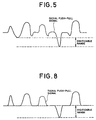
- the radial push-pull signal fluctuates greatly as if a land pre-pit LPP was detected during the period in which the land pre-pit does not exist as shown in Fig. 5, the digitizable range becomes also narrow.
- the digitizable range exists between the peak value of the radial push-pull signal corresponding to the land pre-pit LPP and the peak value of the period in which the land pre-pit does not exist, as shown in Fig. 5. As the digitizable range becomes narrower, setting of the threshold value for digitization becomes more difficult, and the land pre-pit LPP cannot be detected correctly.
- a pre-pit detector for an optical recording medium including a write surface on which an information write track for forming information pits carrying information data and pre-pit track previously having a plurality of pre-pits carrying information associated with the information write track are repeatedly formed in pairs comprising: optical detection means having light reception surfaces split as first and second light reception surfaces in a tangential direction of the track, for receiving a reflected light of an optical beam irradiated to the write surface on the first and second light reception surfaces so as to output first and second optical detection signals corresponding to light reception intensities of the first and second light reception surfaces, and for receiving the reflected beam from the pre-pit track pairing up with the information write track to which the optical beam is irradiated, on the first light reception surface; subtraction means for computing a difference between the first and second optical detection signals generated from the optical detection means; and digitization means for digitizing the output signal of the subtraction means so as to generate the pre-pit detection signal, wherein the optical detection means has amplification means for giving to the first optical detection signal an amplification result
- the construction described above can expand the digitizable range of the radial push-pull signal as the output signal of the subtraction means even when the leak of the information data components from the adjacent tracks exists, or when the variation of the balance resulting from the tracking error of the information-reading spot exists. Since the construction makes it easier to set the threshold value for digitization, the pre-pits of the pre-pit track can be detected more correctly.
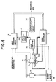
- Fig. 6 shows an information write/read apparatus that applies a pre-pit detector according to the present invention.
- a write beam generator (not shown) for writing information data to a DVD 1 as a write-once or re-writable optical recording medium having a write surface such as the one shown in Fig. 1, a read beam generator (not shown) for generating a read beam for reading written information (inclusive of the information data) from the DVD 1 and a four-split optical detector (reference numeral 20 in Fig. 7) are mounted to a write/read head 2 of the information write/read apparatus.
- Each track GV is shown linearly in Fig. 1, but is wobbled in practice at a frequency corresponding to a rotational speed of the DVD 1.
- the write beam generator and the read beam generator need not be disposed separately but may be one optical beam generator that generates the write beam at the time of writing and the read optical beam at the time of reading.
- the read beam generator irradiates the read beam to the DVD 1 that is driven for rotation by a spindle motor 9, and forms information-reading spots on its write surface.
- the four-split optical detector 20 comprises a photo-electric conversion device having four-split light reception surfaces 20a to 20d that are split by the direction extending along the tangent of the information write tracks (groove track GV) and the direction crossing orthogonally the tangent of the write track in the same way as the four-split optical detector shown in Fig. 2.
- the photo-electric conversion device receives the reflected beam from the information-reading spots of the DVD 1 by its four light reception surfaces 20a to 20d, converts them individually to electric signals and output them as light reception signals Ra to Rd.
- a servo controller 4 generates a focusing error signal, a tracking error signal and a slider driving signal on the basis of these light reception signals Ra to Rd.
- the focusing error signal is supplied to a focusing actuator (not shown) mounted to the write/read head 2.
- the focusing actuator adjusts the focus of each information-reading spot on the basis of the focusing error signal.
- the tracking error signal is supplied to a tracking actuator (not shown) mounted to the write/read head 2.
- the tracking actuator adjusts the formation position of the information-reading spot in the disk radial direction on the basis of the tracking error signal.
- the slider driving signal is supplied to a slider 100.
- the slider 100 transfers the write/read head 2 in the disk radial direction at a speed corresponding to the slider driving signal.
- the light reception signals Ra to Rd are supplied to a head amplifier 25 having adders 21 to 23 and a subtractor 24.
- the adder 21 adds the light reception signals Ra and Rd.
- the adder 22 adds the light reception signals Rb and Rc.
- the adder 21 adds the light reception signals Ra and Rd obtained by receiving the beam by the light reception surfaces 20a and 20d of the four-split optical detector 20, and outputs a sum light reception signal R a+d .
- the adder 22 adds the light reception signals Rb and Rc obtained by receiving the beam by the light reception surfaces 20b and 20c of the four-split optical detector 20, and outputs a sum light reception signal R b+c .
- the adder 23 adds the output signals R a+d and R b+c of the adders 21 and 22.
- the output signal of the adder 23 is the read signal, that is, a RF signal.
- the RF signal is supplied to an information data reproduction circuit 30.
- the information data reproduction circuit 30 digitizes the read signal and sequentially executes a demodulation processing, an error correction processing and various information decoding processing to reproduce and output information data recorded on the DVD 1 (i.e. image data, audio data and computer data).
- the subtractor 24 subtracts the output signal R b+c of the adder 22 from the output signal R a+d of the adder 21.
- the output signal of the subtractor 24 becomes the signal that represents the frequency of the track GV due to wobbling and is supplied to a spindle servo device 26 for the spindle motor 9.
- the spindle servo device 26 drives and rotates the spindle motor 9 so that the frequency obtained from the output signal of the subtractor 24 becomes a frequency corresponding to a predetermined rotational speed. Since the construction of the spindle servo device 26 is described in Japanese Patent Laid-Open No. 10-283638, its explanation will be hereby omitted.
- a pre-pit detection circuit 5 detects the land pre-pits LPP formed on the land tracks LD (prep-pit tracks) of the DVD 1 such as those shown in Fig. 1 on the basis of the output signals of the adders 21 and 22, and supplies the pre-pit detection signals PP D to a write processing circuit 7.
- the write processing circuit 7 recognizes the position at which the write/read head 2 executes writing at the present moment, on the basis of the pre-pit detection signal PP D or in other words, the position on the groove track GV.
- the circuit 7 supplies a control signal for allowing the write/read head 2 to jump from the present write position to a desired write position to the servo controller 4.
- the write processing circuit 7 executes a desired write modulation processing for the information data to be written, generates a write modulation data signal and supplies the signal to the write/read head 2.
- the read beam generator mounted to the write/read head 2 generates the write beam corresponding to such a write modulation data signal and irradiates the optical beam to the groove track GV of the DVD 1. The heat is transferred to the region on the groove track GV to which the write beam is irradiated, and the information pit is formed in the region.
- the pre-pit detection circuit 5 comprises an amplifier 51 for amplifying the output signal R a+d of the adder 21, an amplifier 52 for amplifying the output signal R b+c of the adder 22, a subtractor 53 for subtracting the output signal of the amplifier 52 from the output signal of the amplifier 51 to output the difference as a radial push-pull signal PP, and a digitizing circuit 54 for digitizing the output push-pull signal of the subtractor 53 at a predetermined threshold value to generate the pre-pit detection signal PP D described above, as shown in Fig. 7.
- the gain G1 of the amplifier 51 is set to a value greater than the gain G2 of the amplifier 52, that is, G1/G2 > 1.
- the gain G1 of the amplifier 51 is 1.3, for example, and the gain G2 of the amplifier 52 is 1, for example.
- the gain G1 of the amplifier 51 for amplifying the output signal R a+d of the adder 21 is greater than the gain G2 of the amplifier 52 for amplifier the output signal R b+c of the adder 22. Therefore, even if the output signal R a+d of the adder 21 and the output signal R b+c of the adder 22 exist in the same level when the information-reading spot exists on the groove track GV of the write surface, the output signal level of the amplifier 51 is higher than the output signal level of the amplifier 52.
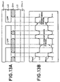
- Figs. 13A and 13B show the waveforms of the signals R a+d and R b+c when the leak of the information components from the adjacent tracks does not exist and the variation of the balance due to the tracking error of the information-reading spot does not exist, either, respectively.
- Figs. 14A and 14B show the waveforms of the signals R a+d and R b+c when the leak of the information data components from the adjacent tracks exists due to so-called "cross-talk" and the variation of the balance due to the tracking error of the information-reading spot exists, too, respectively.
- the recording marks (pits) by the information data are formed in only the groove track GVn as represented by hatching among the groove tracks GVn-1, GVn and GVn+1.
- the light reception signals Ra to Rd do not at all contain the leak components of the information data from the adjacent groove tracks GVn-1 and GVn+1 and the leak components of the RF signal on the groove track GVn that results from the variation of the balance due to the tracking error of the information-reading spot.
- the optical beam irradiated is diffracted at the portion of the write mark. Therefore, the light intensity reaching the light reception surfaces 20a to 20d becomes small.
- the optical beam irradiated is reflected as it is, at portions other than the write mark and reach the light reception surfaces 20a to 20d. Therefore, the light intensity received becomes great.
- the optical beam irradiated is diffracted at the portion of the land pre-pit LPP at which the land pre-pit LPP exists. Therefore, the light intensity received at the light reception surfaces 20a and 20d by the reflected light at the portions inclusive of the land pre-pit LPP decreases whereas the low intensity received on the light reception surfaces 20b and 20c increases, on the contrary.
- the signals R a+d and R b+c change as shown in Fig. 13B. It can be understood from Figs.
- the decreasing quantity of the light reception intensity of the land pre-pits LPP adjacent to the write mark is smaller than the decreasing quantity of the light reception quantity of the land pre-pit LPP adjacent to the portion where the write mark does not exist.
- the light reception quantity is originally small due to the write mark.
- the write marks (hatched portions) of the information data are formed in all of the groove tracks GVn-1, GVn and GVn+1.
- the leak components of the information data and the leak components of the RF signal on the groove track GVn resulting from the variation of the balance resulting from the tracking error of the information-reading spot are contained in the light reception signals Ra to Rd during the read operation of the write mark of the groove track GVn.
- the light intensity reaching the light reception surfaces 20a to 20d becomes small at the portion of the write mark of the groove track GVn but becomes great at portions other than the write mark in the same way as in the cases of Figs. 13A and 13B.
- the light intensity received on the light reception surfaces 20a and 20d decreases at the position at which the land pre-pit LPP exists, and increases on the light reception surfaces 20b and 20c, on the contrary. Furthermore, when the write marks of the groove tracks GVn-1 and GVn+1 are positioned in the disk radial direction against the read point, the leak components due to cross-talk reach the light reception surfaces 20a to 20d as the light intensity fluctuation. As a result, the signals R a+d and R b+c change as shown in Fig. 14B. Fig. 14B shows the signals R a+d and R b+c with the signal R a+d as the reference. Although only the signal R b+c fluctuates, the signal R a+d also fluctuates in practice due to the leak components.
- Fig. 15B shows the waveform of the radial push-pull signal PP generated from the subtractor 53 of the pre-pit detection circuit 5 in accordance with the output signals R a+d and R b+c shown in Fig. 15A.
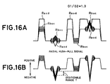
- Fig. 16B shows the waveform of the radial push-pull signal PP generated from the subtractor 53 of the pre-pit detection circuit 5 in accordance with the output signals R a+d and R b+c shown in Fig. 16A.
- the signal R b+c becomes greater in some cases than the signal R a+d as indicated by symbol N in Fig. 15A. Therefore, the influences of the portion N appear in the radial push-pull signal PP as indicated by symbol M in Fig. 15B.
- the portion M has the waveform that protrudes greatly towards the detection level side (to the negative side in Fig. 15B) of the land pre-pit LPP and narrows the digitizable range T.
- the signal R a+d is greater than the signal R b+c with the exception of the portion corresponding to the land pre-pit LPP as shown in Fig. 16A. Therefore, the signal components such as M do not appear greatly towards the negative side in the radial push-pull signal PP with the exception of the portion corresponding to the land pre-pit LPP, as shown in Fig. 16B. On the contrary, the portion of the signal R b+c containing the leak components moves and appears on the positive side of the radial push-pull signal. Therefore, the digitizable range T can be expanded.
- Fig. 17A shows only one line that exerts the worst influences on the digitizable range T of the fluctuation waveform of the output signal R b+c of the amplifier 52 in Fig. 15A.
- the drawing shows also the waveform of the output signal R a+d of the amplifier 51.
- Fig. 17B shows the waveform of the radial push-pull signal PP generated from the subtractor 53 of the pre-pit detection circuit 5 in accordance with the signals R a+d and R c+d shown in Fig. 17A.
- Fig. 18A shows only one line that exerts the worst influences on the digitizable range of the fluctuation waveform of the output signal R b+c of the amplifier 52 shown in Fig. 16A with the waveform of the output signal R a+d of the amplifier 51.
- Fig. 18B shows the waveform of the radial push-pull signal PP generated from the subtractor 53 of the pre-pit detection circuit 5 in accordance with the signals R a+d and R b+c shown in Fig. 18A.
- the portion X of the radial push-pull signal PP that corresponds to the land pre-pit LPP of the radial push-pull signal PP shown in Fig. 18B, moves towards the positive side, and its distal end is included in the signal range Y corresponding to the portion at which the write mark does not exist.
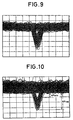
- Figs. 9 and 10 show the waveforms of the radial push-pull signal PP obtained by the actual measurement.
- the waveforms shown in Figs. 9 and 10 represent a large number of sweep lines superposed with one another as the groove tracks GV containing the land pre-pit LPP are detected again and again.
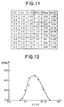
- Fig. 12 is a graph showing characteristic curve the relationship between G1/G2 and AR obtained by such a measurement.
- the dynamic range can be expanded when the digitization circuit 54 executes digitization at the predetermined threshold value Th (as shown in Fig. 8 in comparison with the prior art technology shown in Fig. 5). In consequence, detection accuracy of the land pre-pit detection signal PP D can be improved.
- the predetermined threshold value can be set with a sufficient margin when digitization is conducted.
- the erroneous detection of the land pre-pit LPP can be prevented even when the focusing error, the tracking error and the increase of the cross-talk due to the tilt exist.
- the embodiment described above represents the case wherein the DVD 1 to which the information data has already been written is read.
- this embodiment can similarly generate a radial push-pull signal PP having a broad digitizable range when the information data is written to the DVD 1 to which the information data is not yet written.
- the track to be written and the written tracks adjacent to the former track exist. For the reason, the information data components of the written adjacent tracks leak into the radial push-pull signal PP.
- the present invention can generate a radial push-pull signal PP having a broad digitizable range.
- the present invention can generate a radial push-pull signal PP having a broad digitizable range with hardly any influences of the leak components.
- the amplifiers 51 and 52 need not always be disposed at the output stage of the adders 21 and 22 but may be disposed at their input stage.
- an amplifier Aa for amplifying the light reception signal Ra an amplifier Ab for amplifying the light reception signal Rb, an amplifier Ac for amplifying the light reception signal Rc at the same gain as that of the amplifier Ab and an amplifier Ad for amplifying the light reception signal Rd at the same gain as that of the amplifier Aa are provided in the case.
- the gain of each amplifier Aa, Ad is set to a grater gain than that of each amplifier Ab, Ac.
- the embodiment described above uses the four-split optical detector, but it may use an optical detector having light reception surfaces split into two surfaces in the tangential direction of the tracks. In the case, the amplifiers 21 and 22 need not be disposed.
- pre-pit detector of the present invention can expand the digitizable range of the radial push-pull signal even when the leak of the information data components from the adjacent tracks or the variation of the balance due to the tracking error of the information-reading spot exists. Since setting of the threshold value for digitization becomes easy, the present invention can correctly detect the pre-pit.
Landscapes
- Optical Recording Or Reproduction (AREA)
Abstract
Description
Claims (3)
- A pre-pit detector for an optical recording medium including a write surface on which an information write track for forming information pits carrying information data and pre-pit track previously having a plurality of pre-pits carrying information associated with the information write track are repeatedly formed in pairs, comprising:optical detection means having light reception surfaces split as first and second light reception surfaces in a tangential direction of said track, for receiving a reflected light of an optical beam irradiated to said write surface on said first and second light reception surfaces so as to output first and second optical detection signals corresponding to light reception intensities of said first and second light reception surfaces, and for receiving the reflected beam from said pre-pit track pairing up with said information write track to which the optical beam is irradiated, on said first light reception surface;subtraction means for computing a difference between said first and second optical detection signals generated from said optical detection means; anddigitization means for digitizing the output signal of said subtraction means so as to generate said pre-pit detection signal,
wherein said optical detection means has amplification means for giving to said first optical detection signal an amplification result by a greater gain in comparison with said second optical detection signal so as to output said first and second optical detection signals to said subtraction means. - A pre-pit detector according to claim 1, wherein said amplification means includes a first amplifier for amplifying said first optical detection signal with a first gain and outputting said amplified signal to said subtraction means, and a second amplifier for amplifying said second optical detection signal with a second gain smaller than said first gain and outputting said amplified signal to said subtraction means.
- A pre-pit detector according to claim 2, wherein a ratio of said first gain to said second gain (said first gain/said second gain) is set so that a ratio of the minimum value to the maximum value (minimum value x 100/maximum value) of the output signal of said subtraction means corresponding to said pre-pit becomes greater than that when the ratio of said first gain to said second gain is one.
Applications Claiming Priority (2)
| Application Number | Priority Date | Filing Date | Title |
|---|---|---|---|
| JP19511599A JP3929207B2 (en) | 1999-07-08 | 1999-07-08 | Pre-pit detection device for optical recording medium |
| JP19511599 | 1999-07-08 |
Publications (2)
| Publication Number | Publication Date |
|---|---|
| EP1067524A2 true EP1067524A2 (en) | 2001-01-10 |
| EP1067524A3 EP1067524A3 (en) | 2001-03-21 |
Family
ID=16335753
Family Applications (1)
| Application Number | Title | Priority Date | Filing Date |
|---|---|---|---|
| EP00114002A Withdrawn EP1067524A3 (en) | 1999-07-08 | 2000-07-04 | Pre-pit detector of optical recording medium |
Country Status (3)
| Country | Link |
|---|---|
| US (1) | US6545972B1 (en) |
| EP (1) | EP1067524A3 (en) |
| JP (1) | JP3929207B2 (en) |
Cited By (3)
| Publication number | Priority date | Publication date | Assignee | Title |
|---|---|---|---|---|
| EP1548712A3 (en) * | 2003-11-27 | 2006-04-05 | Pioneer Corporation | Data reading device and pre-pit detection circuit |
| EP1235214A3 (en) * | 2001-02-23 | 2007-04-11 | Pioneer Corporation | Apparatus for inspecting pre-pits of an optical recording medium |
| US7212486B2 (en) | 2001-10-29 | 2007-05-01 | Teac Corporation | Optical disk device setting a gain of an amplifier so that a peak value and a bottom value of wobble signal components coincide |
Families Citing this family (13)
| Publication number | Priority date | Publication date | Assignee | Title |
|---|---|---|---|---|
| JP4136293B2 (en) * | 2000-08-10 | 2008-08-20 | パイオニア株式会社 | Optical recording medium, manufacturing method and manufacturing apparatus |
| JP4226204B2 (en) * | 2000-09-14 | 2009-02-18 | パイオニア株式会社 | Optical recording medium, manufacturing apparatus and manufacturing method thereof |
| JP4561022B2 (en) * | 2000-10-05 | 2010-10-13 | 日本ビクター株式会社 | Recording and / or reproducing apparatus and method |
| JP2002140824A (en) * | 2000-10-31 | 2002-05-17 | Toshiba Corp | Track pull-in method in optical disk device and optical disk device employing this method |
| JP2002216354A (en) * | 2001-01-15 | 2002-08-02 | Pioneer Electronic Corp | Pre-pit detection device |
| JP3736404B2 (en) * | 2001-09-21 | 2006-01-18 | ティアック株式会社 | Optical disk device |
| JP2004022127A (en) * | 2002-06-19 | 2004-01-22 | Pioneer Electronic Corp | Tilt correcting device |
| JP3975139B2 (en) * | 2002-08-30 | 2007-09-12 | パイオニア株式会社 | Tilt correction device and tilt correction method |
| WO2005024800A1 (en) * | 2003-09-02 | 2005-03-17 | Ricoh Company Ltd. | Push-pull signal generation device and optical disc device |
| WO2005086147A1 (en) * | 2004-03-04 | 2005-09-15 | Sony Corporation | Optical disc device optical head and photo-detection device thereof |
| TWI299493B (en) * | 2004-09-23 | 2008-08-01 | Lite On It Corp | An optical disk drive for compensating wobble signal and method thereof |
| US7613093B2 (en) * | 2005-09-28 | 2009-11-03 | Mediatek Inc. | Duty ratio control apparatus for pre-pit detection or header detection of an optical storage medium |
| JP2007319470A (en) * | 2006-06-01 | 2007-12-13 | Konami Gaming Inc | Slot machine |
Family Cites Families (12)
| Publication number | Priority date | Publication date | Assignee | Title |
|---|---|---|---|---|
| JP3260151B2 (en) * | 1991-10-31 | 2002-02-25 | パイオニア株式会社 | Wobble signal reading device and wobble signal reading method |
| US5475662A (en) * | 1992-05-13 | 1995-12-12 | Matsushita Electric Industrial Co., Ltd. | Optical disc apparatus with tracking error compensation |
| JPH0917029A (en) * | 1995-06-26 | 1997-01-17 | Pioneer Electron Corp | Optical disc, its reader, and optical disc manufacturing method |
| US5696752A (en) * | 1996-01-16 | 1997-12-09 | Eastman Kodak Company | Low noise atip detection from an optical recording medium with wobbled grooves |
| JPH09237421A (en) * | 1996-03-01 | 1997-09-09 | Sony Corp | Recording / reproducing apparatus and method |
| JP2924841B2 (en) * | 1997-02-27 | 1999-07-26 | 日本電気株式会社 | Optical information recording apparatus, optical recording medium, and method of determining tracking polarity of optical recording medium |
| JPH10275365A (en) * | 1997-03-28 | 1998-10-13 | Toshiba Corp | Information storage medium and information reproducing apparatus |
| JP3555055B2 (en) | 1997-04-07 | 2004-08-18 | パイオニア株式会社 | Prepit detection device and information recording device |
| JP3887480B2 (en) * | 1998-03-20 | 2007-02-28 | パイオニア株式会社 | Pre-pit detection device |
| JP2000099952A (en) * | 1998-09-17 | 2000-04-07 | Nec Corp | Optical disk and optical disk device |
| JP3872235B2 (en) * | 1998-10-21 | 2007-01-24 | パイオニア株式会社 | Pre-pit detection device |
| JP2000132835A (en) * | 1998-10-23 | 2000-05-12 | Pioneer Electronic Corp | Disk player |
-
1999
- 1999-07-08 JP JP19511599A patent/JP3929207B2/en not_active Expired - Lifetime
-
2000
- 2000-07-04 EP EP00114002A patent/EP1067524A3/en not_active Withdrawn
- 2000-07-07 US US09/610,690 patent/US6545972B1/en not_active Expired - Fee Related
Cited By (3)
| Publication number | Priority date | Publication date | Assignee | Title |
|---|---|---|---|---|
| EP1235214A3 (en) * | 2001-02-23 | 2007-04-11 | Pioneer Corporation | Apparatus for inspecting pre-pits of an optical recording medium |
| US7212486B2 (en) | 2001-10-29 | 2007-05-01 | Teac Corporation | Optical disk device setting a gain of an amplifier so that a peak value and a bottom value of wobble signal components coincide |
| EP1548712A3 (en) * | 2003-11-27 | 2006-04-05 | Pioneer Corporation | Data reading device and pre-pit detection circuit |
Also Published As
| Publication number | Publication date |
|---|---|
| JP2001023168A (en) | 2001-01-26 |
| JP3929207B2 (en) | 2007-06-13 |
| EP1067524A3 (en) | 2001-03-21 |
| US6545972B1 (en) | 2003-04-08 |
Similar Documents
| Publication | Publication Date | Title |
|---|---|---|
| US5537373A (en) | Optical disk recording and reproducing apparatus with data recorded on wobbled grooves and lands | |
| JP3063596B2 (en) | Optical disk device and optical disk | |
| US6545972B1 (en) | Pre-pit detector of optical recording medium | |
| US6621774B2 (en) | Optical disk device | |
| JP3560410B2 (en) | Optical disk device and optical disk | |
| EP1244099A2 (en) | Wobble detection circuit and optical disk apparatus | |
| US8472290B2 (en) | Apparatus and method identifying disc type | |
| EP1043714B1 (en) | Optical recording medium | |
| KR100327203B1 (en) | Optical disc recording media having tilt dection pattern | |
| HK1033499A (en) | Pre-pit detector of optical recording medium | |
| US20050157617A1 (en) | Apparatus and method for detecting a pre-pit signal | |
| JP2508761B2 (en) | Optical memory playback device | |
| US7016285B2 (en) | Linking gap detecting device and method of optical recording medium | |
| WO2004081928A1 (en) | Optical disk | |
| JP4076646B2 (en) | Optical disk device | |
| US20030198174A1 (en) | Optical pickup apparatus and optical disk apparatus | |
| US20070217317A1 (en) | Optical disk device, playback method of the optical disk device, and reproduction signal generating circuit | |
| JPH0684194A (en) | Optical disk apparatus | |
| KR100713373B1 (en) | Tracking Servo Adjustment Method for Optical Disc Device | |
| KR100547976B1 (en) | Reproducing Apparatus For Optical Recording Media | |
| JP4341342B2 (en) | Optical pickup device and recording / reproducing device | |
| JP4396707B2 (en) | Optical disk device | |
| TWI248077B (en) | Embossed region detection apparatus and method for optical disk | |
| KR100549663B1 (en) | Optical Recording Medium And Apparatus For Driving The Same | |
| JP2005353195A (en) | Wobble signal detection circuit and optical disk apparatus |
Legal Events
| Date | Code | Title | Description |
|---|---|---|---|
| PUAI | Public reference made under article 153(3) epc to a published international application that has entered the european phase |
Free format text: ORIGINAL CODE: 0009012 |
|
| AK | Designated contracting states |
Kind code of ref document: A2 Designated state(s): DE FR GB |
|
| AX | Request for extension of the european patent |
Free format text: AL;LT;LV;MK;RO;SI |
|
| PUAL | Search report despatched |
Free format text: ORIGINAL CODE: 0009013 |
|
| AK | Designated contracting states |
Kind code of ref document: A3 Designated state(s): AT BE CH CY DE DK ES FI FR GB GR IE IT LI LU MC NL PT SE |
|
| AX | Request for extension of the european patent |
Free format text: AL;LT;LV;MK;RO;SI |
|
| 17P | Request for examination filed |
Effective date: 20010321 |
|
| AKX | Designation fees paid |
Free format text: DE FR GB |
|
| 17Q | First examination report despatched |
Effective date: 20070405 |
|
| STAA | Information on the status of an ep patent application or granted ep patent |
Free format text: STATUS: THE APPLICATION IS DEEMED TO BE WITHDRAWN |
|
| 18D | Application deemed to be withdrawn |
Effective date: 20071016 |
|
| REG | Reference to a national code |
Ref country code: HK Ref legal event code: WD Ref document number: 1033499 Country of ref document: HK |