EP1067397B1 - Motion detector based on the Doppler principle - Google Patents
Motion detector based on the Doppler principle Download PDFInfo
- Publication number
- EP1067397B1 EP1067397B1 EP99112885A EP99112885A EP1067397B1 EP 1067397 B1 EP1067397 B1 EP 1067397B1 EP 99112885 A EP99112885 A EP 99112885A EP 99112885 A EP99112885 A EP 99112885A EP 1067397 B1 EP1067397 B1 EP 1067397B1
- Authority
- EP
- European Patent Office
- Prior art keywords
- signals
- motion sensor
- microwave
- detector
- channels
- Prior art date
- Legal status (The legal status is an assumption and is not a legal conclusion. Google has not performed a legal analysis and makes no representation as to the accuracy of the status listed.)
- Expired - Lifetime
Links
- 230000009466 transformation Effects 0.000 claims abstract description 29
- 230000005855 radiation Effects 0.000 claims abstract description 8
- 238000011156 evaluation Methods 0.000 claims abstract description 7
- 230000009977 dual effect Effects 0.000 claims description 8
- 238000012545 processing Methods 0.000 claims description 6
- 238000012544 monitoring process Methods 0.000 abstract description 4
- 238000005259 measurement Methods 0.000 description 8
- 241000238631 Hexapoda Species 0.000 description 5
- 241001465754 Metazoa Species 0.000 description 4
- 230000008901 benefit Effects 0.000 description 4
- 238000000034 method Methods 0.000 description 4
- 230000010354 integration Effects 0.000 description 2
- 230000001960 triggered effect Effects 0.000 description 2
- 125000004122 cyclic group Chemical group 0.000 description 1
- 238000001514 detection method Methods 0.000 description 1
- 238000010586 diagram Methods 0.000 description 1
- 230000000694 effects Effects 0.000 description 1
- 238000001914 filtration Methods 0.000 description 1
- 230000008569 process Effects 0.000 description 1
- 230000003595 spectral effect Effects 0.000 description 1
- 230000001629 suppression Effects 0.000 description 1
- 238000002604 ultrasonography Methods 0.000 description 1
Images
Classifications
-
- G—PHYSICS
- G01—MEASURING; TESTING
- G01S—RADIO DIRECTION-FINDING; RADIO NAVIGATION; DETERMINING DISTANCE OR VELOCITY BY USE OF RADIO WAVES; LOCATING OR PRESENCE-DETECTING BY USE OF THE REFLECTION OR RERADIATION OF RADIO WAVES; ANALOGOUS ARRANGEMENTS USING OTHER WAVES
- G01S13/00—Systems using the reflection or reradiation of radio waves, e.g. radar systems; Analogous systems using reflection or reradiation of waves whose nature or wavelength is irrelevant or unspecified
- G01S13/02—Systems using reflection of radio waves, e.g. primary radar systems; Analogous systems
- G01S13/06—Systems determining position data of a target
- G01S13/08—Systems for measuring distance only
- G01S13/32—Systems for measuring distance only using transmission of continuous waves, whether amplitude-, frequency-, or phase-modulated, or unmodulated
- G01S13/34—Systems for measuring distance only using transmission of continuous waves, whether amplitude-, frequency-, or phase-modulated, or unmodulated using transmission of continuous, frequency-modulated waves while heterodyning the received signal, or a signal derived therefrom, with a locally-generated signal related to the contemporaneously transmitted signal
- G01S13/348—Systems for measuring distance only using transmission of continuous waves, whether amplitude-, frequency-, or phase-modulated, or unmodulated using transmission of continuous, frequency-modulated waves while heterodyning the received signal, or a signal derived therefrom, with a locally-generated signal related to the contemporaneously transmitted signal using square or rectangular modulation, e.g. diplex radar for ranging over short distances
-
- G—PHYSICS
- G01—MEASURING; TESTING
- G01S—RADIO DIRECTION-FINDING; RADIO NAVIGATION; DETERMINING DISTANCE OR VELOCITY BY USE OF RADIO WAVES; LOCATING OR PRESENCE-DETECTING BY USE OF THE REFLECTION OR RERADIATION OF RADIO WAVES; ANALOGOUS ARRANGEMENTS USING OTHER WAVES
- G01S13/00—Systems using the reflection or reradiation of radio waves, e.g. radar systems; Analogous systems using reflection or reradiation of waves whose nature or wavelength is irrelevant or unspecified
- G01S13/02—Systems using reflection of radio waves, e.g. primary radar systems; Analogous systems
- G01S13/50—Systems of measurement based on relative movement of target
- G01S13/52—Discriminating between fixed and moving objects or between objects moving at different speeds
- G01S13/56—Discriminating between fixed and moving objects or between objects moving at different speeds for presence detection
-
- G—PHYSICS
- G01—MEASURING; TESTING
- G01S—RADIO DIRECTION-FINDING; RADIO NAVIGATION; DETERMINING DISTANCE OR VELOCITY BY USE OF RADIO WAVES; LOCATING OR PRESENCE-DETECTING BY USE OF THE REFLECTION OR RERADIATION OF RADIO WAVES; ANALOGOUS ARRANGEMENTS USING OTHER WAVES
- G01S13/00—Systems using the reflection or reradiation of radio waves, e.g. radar systems; Analogous systems using reflection or reradiation of waves whose nature or wavelength is irrelevant or unspecified
- G01S13/86—Combinations of radar systems with non-radar systems, e.g. sonar, direction finder
Definitions
- the invention relates to a motion detector according to the Doppler principle, with a microwave module for emitting a microwave signal containing at least two frequencies in a monitoring room and for receiving the radiation reflected therefrom, and with a connected to the microwave module evaluation stage, in which from the received reflected radiation first and second Doppler signals are generated which have a phase difference proportional to the distance of an object moving in the interstitial space.
- Moving detectors operating on the Doppler principle used either alone or as so-called dual detectors in conjunction with passive infrared detectors, have the weakness of having small objects close to the detector, such as insects or raindrops, from distant, larger objects only very much are difficult to distinguish, so that distinguishing more distant people from small domestic animals in the middle distance and from very close insects is made much more difficult or even impossible.
- oscillating fixed objects such as curtains or window casements moving by the wind, or even fans, can not be distinguished from actual movement processes. Due to these disadvantages, these motion detectors have a relatively high false alarm rate and are therefore used practically exclusively as dual detectors.
- US-A-4 203 113 also shows a microwave signal with alternating frequencies for the measurement of distance and direction of movement.
- the invention will now be given a motion detector of the type mentioned, in which the said disturbances are reliably suppressed.
- the integral transformation has the advantage over other methods of phase measurement that noise and other disturbances are better suppressed.
- a first preferred embodiment of the movement detector according to the invention is characterized in that the integral transformation is additionally used for determining the sign of the phase difference and / or the radial velocity of the relevant object relative to the detector.
- a second preferred embodiment of the motion detector according to the invention is characterized in that the integral transformation is additionally used for determining the signal strength of the received signal.
- a third preferred embodiment of the motion detector according to the invention is characterized in that two channels are connected downstream of the output of the microwave module, in which the signals are amplified, filtered and each supplied to an analog / digital converter, and in that the integral transformation consists in the amounts of the signals in to integrate the two channels, to multiply the signals and also to integrate the result of this multiplication, and to divide the resulting signal.
- a fourth preferred embodiment of the motion detector according to the invention is characterized in that the microwave module is designed to emit a microwave signal containing more than two frequencies.
- This embodiment has the advantage that, by emitting more than two frequencies, ambiguities, which can occur in two-frequency operation, are resolved.
- ambiguities may, for example, be caused by distant reflections, which are suppressed in the motion detector described in the aforementioned US-A-4,697,184 by relatively expensive and therefore expensive hardware.
- a fifth preferred embodiment of the motion detector according to the invention is characterized in that the output of the microwave module is followed by a number of frequencies corresponding number of channels in which the signals are amplified, filtered and each supplied to an analog / digital converter, and that the integral transformation by a Fourier transform, a fast Fourier transform or a wavelet transform is formed.
- a sixth preferred embodiment of the motion detector according to the invention is characterized in that the microwave module and the evaluation stage form part of a first detector of a dual detector, which also contains a second detector, preferably a passive infrared detector, and that the signals of the first and those of the second detector common processing stage are supplied, in which a linkage of said signals takes place.
- the result of the linking contains a statement about the quality of the object moving in the interstitial space.
- the dual detector shown consists of a microwave detector 1, a passive infrared detector 2 and a common processing stage 3, at the output of an alarm signal is available in the presence of an unauthorized intruder in the monitored by the detector monitoring space monitored.
- the microwave detector 1 contains a microwave module 4 for transmitting and receiving microwaves.
- the microwave module 4 is associated with a microwave generator 5, which generates a microwave signal having at least two fixed frequencies f 1 and f 2 , which are supplied to the microwave module 4 and a downstream switch 6 periodically. The microwave module 4 is thus periodically switched between the two frequencies f 1 and f 2 and the switch 6 is actuated accordingly.
- the corresponding Doppler signals at the output of the receive mixer have a defined phase relationship with each other.
- the phase difference ⁇ at the output of the receiving mixer results ⁇ ⁇ ( 2 ⁇ / c ) r where c is the speed of light and r the distance sought from the detector to the object reflecting the microwave radiation.
- This equation also applies unchanged in the case of several fixed frequencies (multiplex).
- the phase measurement is cyclic; the resulting ambiguity of the result for the distance r must be eliminated by limiting the range of the microwave module or a suitable frequency multiplex.
- the output signal of the microwave module 4 is distributed to two identical channels K 1 and K 2 , in which the signals are amplified and filtered and each one analog / digital converter 7 1 and 7 2 are supplied.
- the digital signals subsequently become another digital filtering for the removal of interference (not shown) of an evaluation stage 8, in which there is essentially an integral transformation of the signals of the two channels K 1 and K 2 .
- Integral transformation is generally the transformation of a function, the so-called object function, effected by an integral operator into another function, the so-called result function, which is also called an integral transformation image, in order to obtain result functions which are easier to handle and from which easier results are obtained To achieve object function.
- an integral transformation examples include Fourier transformation, Fast Fourier transformation, Laplace transformation and wavelet transformation. These methods are used in the present case especially when the microwave signal contains more than two frequencies and accordingly more than two channels K 1 and K 2 are provided. With only two frequencies f 1 and f 2 and correspondingly two channels K 1 and K 2 , the integral transformation consists in integrating the amounts of the signals in the two channels K 1 and K 2 , multiplying the signals and also adding the result of the multiplication integrate and then divide the resulting three integrals upside down. This division provides the cosine of the phase difference ⁇ and thus directly the sought distance r. In addition to the distance r, the integral transformation can also be used to derive the direction of movement (sign d), the radial velocity v of the object relative to the detector and the signal strength s of the received signal.
- phase and amplitude are obtained.
- the signals of a moving object give approximately the same frequency and amplitude but different phase in all channels.
- the amount of the phase difference of two channels is proportional to the distance r, and the sign d of the phase difference of two channels gives the direction of movement. If the phase difference of two channels is formed so that the phase resulting from the channel with the higher transmitter frequency is subtracted from the phase resulting from the channel with a lower transmitter frequency, the resulting sign for a move away from the microwave module 4 is positive and for a move on this too negative.
- the sign can be obtained, for example, by differentiating the phase differences of successive measurements, ie by differentiating the phase after time.
- negative d ⁇ / dt means a movement towards the microwave module 4 and positive d ⁇ / dt a movement away from it.
- the amplitude which is approximately equal in both channels, is obtained directly by integrating the magnitudes of the signals.
- the frequency is obtained, however not from the integrals, but, for example, by counting the zero crossings in a certain time interval.
- the mentioned parameters are supplied to the processing stage 3, which is also connected to the passive infrared detector 2.
- the passive infrared detector 2 is assumed to be known and therefore will not be described here. Reference is made in this connection, for example, to EP-A-0 646 901, EP-A-0 303 913 and EP-A-0 707 294.
- the passive infrared detector 2 responds to the body radiation of a person in the infrared spectral range and the microwave detector 1 to the frequency shift caused by the Doppler effect of the ultrasound reflected by a moving intruder.
- the four parameters r, v, d and s of the microwave detector 1 and the signals of the passive infrared detector 2 are linked together in such a way that an indication of the quality of the moving object can be made.
- an alarm is set, while for the statements, "fan”, “small animal” or “insect” no further actions are necessary.
- the motion detector has, of course, a designated as anti-masking device for tamper monitoring. This does not form object of the present invention and is therefore not described here. Reference is made in this connection to European Patent Application No. 99 110 848.1 assigned to the assignee of the present patent application and to EP-A-0 476 397.
- the description of the microwave detector 1 as part of a dual detector is not intended to be limiting and in particular does not mean that the microwave detector 1 could not be used alone as an autonomous microwave detector.
- the movement detector according to the invention has the main advantages that the false alarm rate is massively improved by distance-independent suppression of the signals triggered by small animals and insects, and that noise and other disturbances can be better suppressed by the integral transformation.
- several moving objects can be resolved, which, however, makes considerably higher demands on the digital signal processing, in particular with regard to storage space and computing power.
Landscapes
- Engineering & Computer Science (AREA)
- Radar, Positioning & Navigation (AREA)
- Remote Sensing (AREA)
- Computer Networks & Wireless Communication (AREA)
- Physics & Mathematics (AREA)
- General Physics & Mathematics (AREA)
- Radar Systems Or Details Thereof (AREA)
- Ultra Sonic Daignosis Equipment (AREA)
- Measurement Of Velocity Or Position Using Acoustic Or Ultrasonic Waves (AREA)
- Burglar Alarm Systems (AREA)
Abstract
Description
Die Erfindung betrifft einen Bewegungsmelder nach dem Doppler-Prinzip, mit einem Mikrowellenmodul zur Aussendung eines mindestens zwei Frequenzen enthaltenden Mikrowellensignals in einen Überwachungsraum und zum Empfang der aus diesem reflektierten Strahlung, und mit einer an das Mikrowellenmodul angeschlossenen Auswertestufe, in welcher aus der empfangenen reflektierten Strahlung erste und zweite Dopplersignale erzeugt werden, welche einen der Entfernung eines sich im Überwachungsraum bewegenden Objekts proportionalen Phasenunterschied aufweisen.The invention relates to a motion detector according to the Doppler principle, with a microwave module for emitting a microwave signal containing at least two frequencies in a monitoring room and for receiving the radiation reflected therefrom, and with a connected to the microwave module evaluation stage, in which from the received reflected radiation first and second Doppler signals are generated which have a phase difference proportional to the distance of an object moving in the interstitial space.
Nach dem Doppler-Prinzip arbeitende Bewegungsmelder, die entweder alleine oder als sogenannte Dualmelder in Verbindung mit Passiv-Infrarotmeldern verwendet werden, haben die Schwäche, dass nahe beim Melder befindliche kleine Objekte, wie beispielsweise Insekten oder Regentropfen, von weiter entfernten, grösseren Objekten nur sehr schwer unterscheidbar sind, so dass eine Unterscheidung von weiter entfernten Menschen von kleinen Haustieren in mittlerer Entfernung und von ganz nahen Insekten stark erschwert oder gar verunmöglicht wird. Ausserdem besteht das Problem, dass oszillierende ortsfeste Gegenstände, wie beispielsweise vom Wind bewegte Vorhänge oder Fensterflügel oder auch Ventilatoren, von tatsächlichen Bewegungsvorgängen nicht unterschieden werden können. Aufgrund dieser Nachteile weisen diese Bewegungsmelder eine relativ hohe Fehlalarmrate auf und werden daher praktisch ausschliesslich als Dualmelder eingesetzt.Moving detectors operating on the Doppler principle, used either alone or as so-called dual detectors in conjunction with passive infrared detectors, have the weakness of having small objects close to the detector, such as insects or raindrops, from distant, larger objects only very much are difficult to distinguish, so that distinguishing more distant people from small domestic animals in the middle distance and from very close insects is made much more difficult or even impossible. In addition, there is the problem that oscillating fixed objects, such as curtains or window casements moving by the wind, or even fans, can not be distinguished from actual movement processes. Due to these disadvantages, these motion detectors have a relatively high false alarm rate and are therefore used practically exclusively as dual detectors.
Zur Vermeidung der erwähnten Nachteile wurde in der US-A- 4 697 184 vorgeschlagen, ein Mikrowellensignal mit alternierenden Frequenzen auszusenden und aus dem von einem Objekt im Überwachungsraum reflektierten Signal erste und zweite Dopplersignale abzuleiten, welche einen der Entfernung des Objekts proportionale Phasenunterschied aufweisen. Der Phasenunterschied wird gemessen und es wird ein Alarmsignal ausgelöst, wenn dieser für eine bestimmte Dauer einen vorgegebenen Grenzwert überschreitet. Bei diesem System werden Störungen durch Mehrwegausbreitung, wie beispielsweise Reflexionen an Wänden, Boden und Decke, und Rauschen nicht oder nur sehr schwach unterdrückt.In order to avoid the mentioned disadvantages it has been proposed in US Pat. No. 4,697,184 to emit a microwave signal with alternating frequencies and derive from the signal reflected by an object in the interstitial space first and second Doppler signals having a phase difference proportional to the distance of the object. The phase difference is measured and an alarm signal is triggered if it exceeds a predetermined limit for a certain duration. In this system disturbances due to multipath propagation, such as reflections on walls, floor and ceiling, and noise are not or only very slightly suppressed.
Der US-A-4 203 113 zeigt auch ein Mikrowellensignal mit alternierenden Frequenzen für die Messung von Entfernung und Bewegungsrichtung.US-A-4 203 113 also shows a microwave signal with alternating frequencies for the measurement of distance and direction of movement.
Durch die Erfindung soll nun ein Bewegungsmelder der eingangs genannten Art angegeben werden, bei dem die genannten Störungen sicher unterdrückt werden.The invention will now be given a motion detector of the type mentioned, in which the said disturbances are reliably suppressed.
Diese Aufgabe wird erfindungsgemäss dadurch gelöst, dass die Bestimmung des Phasenunterschieds durch eine Integraltransformation erfolgt.This object is achieved according to the invention in that the determination of the phase difference is effected by an integral transformation.
Die Integraltransformation hat gegenüber anderen Verfahren zur Phasenmessung den Vorteil, dass Rauschen und andere Störungen besser unterdrückt werden.The integral transformation has the advantage over other methods of phase measurement that noise and other disturbances are better suppressed.
Eine erste bevorzugte Ausführungsform des erfindungsgemässen Bewegungsmelders ist dadurch gekennzeichnet, dass die Integraltransformation zusätzlich zur Bestimmung des Vorzeichens der Phasendifferenz und/oder der Radialgeschwindigkeit des betreffenden Objekts relativ zum Melder verwendet wird.A first preferred embodiment of the movement detector according to the invention is characterized in that the integral transformation is additionally used for determining the sign of the phase difference and / or the radial velocity of the relevant object relative to the detector.
Eine zweite bevorzugte Ausführungsform des erfindungsgemässen Bewegungsmelders ist dadurch gekennzeichnet, dass die Integraltransformation zusätzlich zur Bestimmung der Signalstärke des empfangenen Signals verwendet wird.A second preferred embodiment of the motion detector according to the invention is characterized in that the integral transformation is additionally used for determining the signal strength of the received signal.
Eine dritte bevorzugte Ausführungsform des erfindungsgemässen Bewegungsmelders ist dadurch gekennzeichnet, dass dem Ausgang des Mikrowellenmoduls zwei Kanäle nachgeschaltet sind, in denen die Signale verstärkt, gefiltert und je einem Analog-/Digitalwandler zugeführt werden, und dass die Integraltransformation darin besteht, die Beträge der Signale in den beiden Kanälen zu integrieren, die Signale zu multiplizieren und das Ergebnis dieser Multiplikation ebenfalls zu integrieren, sowie die sich ergebenden Signal zu dividieren.A third preferred embodiment of the motion detector according to the invention is characterized in that two channels are connected downstream of the output of the microwave module, in which the signals are amplified, filtered and each supplied to an analog / digital converter, and in that the integral transformation consists in the amounts of the signals in to integrate the two channels, to multiply the signals and also to integrate the result of this multiplication, and to divide the resulting signal.
Eine vierte bevorzugte Ausführungsform des erfindungsgemässen Bewegungsmelders ist dadurch gekennzeichnet, dass das Mikrowellenmodul zur Aussendung eines mehr als zwei Frequenzen enthaltenden Mikrowellensignals ausgebildet ist.A fourth preferred embodiment of the motion detector according to the invention is characterized in that the microwave module is designed to emit a microwave signal containing more than two frequencies.
Diese Ausführungsform hat den Vorteil, dass durch die Aussendung von mehr als zwei Frequenzen Mehrdeutigkeiten, wie sie beim Zweifrequenzbetrieb auftreten können, aufgelöst werden. Solche Mehrdeutigkeiten können beispielsweise durch weit entfernte Reflexionen verursacht sein, die bei dem in der genannten US-A-4 697 184 beschriebenen Bewegungsmelder durch eine relativ aufwendige und damit teure Hardware unterdrückt werden.This embodiment has the advantage that, by emitting more than two frequencies, ambiguities, which can occur in two-frequency operation, are resolved. Such ambiguities may, for example, be caused by distant reflections, which are suppressed in the motion detector described in the aforementioned US-A-4,697,184 by relatively expensive and therefore expensive hardware.
Eine fünfte bevorzugte Ausführungsform des erfindungsgemässen Bewegungsmelders ist dadurch gekennzeichnet, dass dem Ausgang des Mikrowellenmoduls eine der Anzahl der Frequenzen entsprechende Zahl von Kanälen nachgeschaltet ist, in denen die Signale verstärkt, gefiltert und je einem Analog-/Digitalwandler zugeführt werden, und dass die Integraltransformation durch eine Fourier-Transformation, eine Fast-Fourier-Transformation oder eine Wavelet-Transformation gebildet ist.A fifth preferred embodiment of the motion detector according to the invention is characterized in that the output of the microwave module is followed by a number of frequencies corresponding number of channels in which the signals are amplified, filtered and each supplied to an analog / digital converter, and that the integral transformation by a Fourier transform, a fast Fourier transform or a wavelet transform is formed.
Eine sechste bevorzugte Ausführungsform des erfindungsgemässen Bewegungsmelders ist dadurch gekennzeichnet, dass das Mikrowellenmodul und die Auswertestufe Teil eines ersten Detektors eines Dualmelders bilden, welcher ausserdem einen zweiten Detektor, vorzugsweise einen Passiv-Infrarotdetektor enthält, und dass die Signale des ersten und diejenigen des zweiten Detektors einer gemeinsamen Verarbeitungsstufe zugeführt sind, in welcher eine Verknüpfung der genannten Signale erfolgt.A sixth preferred embodiment of the motion detector according to the invention is characterized in that the microwave module and the evaluation stage form part of a first detector of a dual detector, which also contains a second detector, preferably a passive infrared detector, and that the signals of the first and those of the second detector common processing stage are supplied, in which a linkage of said signals takes place.
Bei einer weiteren bevorzugten Ausführungsform des erfindungsgemässen Bewegungsmelders enthält das Ergebnis der Verknüpfung eine Aussage über die Qualität des sich im Überwachungsraum bewegenden Objekts.In a further preferred embodiment of the motion detector according to the invention, the result of the linking contains a statement about the quality of the object moving in the interstitial space.
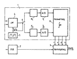
Im folgenden wird die Erfindung anhand eines in der einzigen Zeichnung dargestellten Ausführungsbeispiels näher erläutert. Dieses zeigt ein Blockschema eines aus einem erfindungsgemässen Mikrowellenmelder und aus einem Passiv-Infrarotmelder bestehenden Dualmelders.In the following the invention will be explained in more detail with reference to an embodiment shown in the single drawing. This shows a block diagram of a dual detector according to the invention consisting of a microwave detector and a passive infrared detector.
Der dargestellte Dualmelder besteht aus einem Mikrowellenmelder 1, einem Passiv-Infrarotmelder 2 und einer gemeinsamen Verarbeitungsstufe 3, an deren Ausgang bei Vorhandensein eines unbefugten Eindringlings in dem vom dargestellten Melder überwachten Überwachungsraum ein Alarmsignal erhältlich ist. Der Mikrowellenmelder 1 enthält ein Mikrowellenmodul 4 zur Aussendung und zum Empfang von Mikrowellen. Dem Mikrowellenmodul 4 ist ein Mikrowellengenerator 5 zugeordnet, der ein Mikrowellensignal mit mindestens zwei festen Frequenzen f1 und f2 erzeugt, welche dem Mikrowellenmodul 4 und einem diesem nachgeschalteten Schalter 6 periodisch zugeführt werden. Das Mikrowellenmodul 4 wird also periodisch zwischen den beiden Frequenzen f1 und f2 umgeschaltet und der Schalter 6 wird entsprechend betätigt.The dual detector shown consists of a
In der Radartechnik sind verschiedene Verfahren zur Abstandsmessung bekannt, wobei die beiden gebräuchlichsten entweder die Zeit, die ein kurzer Sendepuls von der Sendeantenne zum Objekt und zurück zur Empfangsantenne benötigt (Pulsradar mit Laufzeitmessung) messen, oder die Differenzfrequenz zwischen dem ausgesandten Signal mit der Frequenz f zur Zeit t und dem Empfangssignal, das zur Zeit t-Δ mit einer anderen Frequenz f-Δf gesendet wurde (FM-Radar).In radar technology, various methods for distance measurement are known, the two most common either the time that a short transmit pulse from the transmitting antenna to the object and back to the receiving antenna (pulse radar with time measurement) measure, or the difference frequency between the transmitted signal with the frequency f at time t and the reception signal sent at time t-Δ at another frequency f-Δf (FM radar).
Wenn in einem Doppler-Radar zwei oder mehr fixe Frequenzen verwendet werden, dann haben die entsprechenden Dopplersignale am Ausgang des Empfangsmischers zueinander eine definierte Phasenbeziehung. Im Fall von zwei fixen Frequenzen (Diplex) f1 und f2 mit einem Frequenzunterschied Δω ergibt sich der Phasenunterschied Δϕ am Ausgang des Empfangsmischers zu ![]()
wobei c die Lichtgeschwindigkeit und r die gesuchte Distanz vom Melder zu dem die Mikrowellenstrahlung reflektierenden Objekt ist. Diese Gleichung gilt unverändert auch für den Fall von mehreren fixen Frequenzen (Multiplex). Die Phasenmessung ist zyklisch; die entstehende Mehrdeutigkeit des Resultats für die Distanz r muss durch Begrenzung der Reichweite des Mikrowellenmoduls oder ein geeignetes Frequenzmultiplex beseitigt werden.If two or more fixed frequencies are used in a Doppler radar, then the corresponding Doppler signals at the output of the receive mixer have a defined phase relationship with each other. In the case of two fixed frequencies (diplex) f 1 and f 2 with a frequency difference Δω, the phase difference Δφ at the output of the receiving mixer results ![]()
where c is the speed of light and r the distance sought from the detector to the object reflecting the microwave radiation. This equation also applies unchanged in the case of several fixed frequencies (multiplex). The phase measurement is cyclic; the resulting ambiguity of the result for the distance r must be eliminated by limiting the range of the microwave module or a suitable frequency multiplex.
Durch den Schalter 6 wird das Ausgangssignal des Mikrowellenmoduls 4 auf zwei identische Kanäle K1 und K2 verteilt, in denen die Signale verstärkt und gefiltert und je einem Analog-/Digitalwandler 71 bzw. 72 zugeführt werden. Die digitalen Signale werden anschliessend nach einer weiteren digitalen Filterung zur Entfernung von Störungen (nicht dargestellt) einer Auswertestufe 8 zugeführt, in welcher im wesentlichen eine Integraltransformation der Signale der beiden Kanäle K1 und K2 erfolgt. Integraltransformation ist ganz allgemein die durch einen Integraloperator bewirkte Transformation einer funktion, der sogenannten Objektfunktion, in eine andere Funktion, die sogenannte Resultatfunktion, die auch als Bild der Integraltransformation bezeichnet wird, um einfacher zu handhabende Resultatfunktionen zu erhalten und aus deren Behandlung leichter Ergebnisse über die Objektfunktion zu erzielen.By the switch 6, the output signal of the microwave module 4 is distributed to two identical channels K 1 and K 2 , in which the signals are amplified and filtered and each one analog / digital converter 7 1 and 7 2 are supplied. The digital signals subsequently become another digital filtering for the removal of interference (not shown) of an
Beispiele für eine Integraltransformation sind Fourier-Transformation, Fast-Fourier-Transformation, Laplace-Transformation und Wavelet-Transformation. Diese Verfahren werden im vorliegenden Fall besonders dann angewendet, wenn das Mikrowellensignal mehr als zwei Frequenzen enthält und dementsprechend auch mehr als zwei Kanäle K1 und K2 vorgesehen sind. Bei nur zwei Frequenzen f1 und f2 und entsprechend zwei Kanälen K1 und K2 besteht die Integraltransformation darin, die Beträge der Signale in den beiden Kanälen K1 und K2 zu integrieren, die Signale zu multiplizieren und das Ergebnis der Multiplikation ebenfalls zu integrieren und dann die sich ergebenden drei Integrale durcheinander zu dividieren. Diese Division liefert den Cosinus des Phasenunterschieds Δϕ und damit unmittelbar die gesuchte Distanz r. Zusätzlich zur Distanz r kann aus der Integraltransformation auch die Bewegungsrichtung (Vor-zeichen d), die Radialgeschwindigkeit v des Objekts relativ zum Melder und die Signalstärke s des empfangenen Signals abgeleitet werden.Examples of an integral transformation are Fourier transformation, Fast Fourier transformation, Laplace transformation and wavelet transformation. These methods are used in the present case especially when the microwave signal contains more than two frequencies and accordingly more than two channels K 1 and K 2 are provided. With only two frequencies f 1 and f 2 and correspondingly two channels K 1 and K 2 , the integral transformation consists in integrating the amounts of the signals in the two channels K 1 and K 2 , multiplying the signals and also adding the result of the multiplication integrate and then divide the resulting three integrals upside down. This division provides the cosine of the phase difference Δφ and thus directly the sought distance r. In addition to the distance r, the integral transformation can also be used to derive the direction of movement (sign d), the radial velocity v of the object relative to the detector and the signal strength s of the received signal.
Wenn beispielsweise eine Fourier-Transformation verwendet wird, dann werden pro Kanal direkt die Grössen Frequenz (proportional zur Radialgeschwindigkeit), Phase und Amplitude gewonnen. Die Signale eines bewegten Objekts ergeben in allen Kanälen annähernd dieselbe Frequenz und Amplitude, aber unterschiedliche Phase. Dabei ist der Betrag der Phasendifferenz zweier Kanäle proportional zum Abstand r, und das Vorzeichen d der Phasendifferenz zweier Kanäle ergibt die Bewegungsrichtung. Wenn die Phasendifferenz zweier Kanäle derart gebildet wird, dass die Phase resultierend aus dem Kanal mit der höheren Senderfrequenz von der Phase resultierend aus dem Kanal mit einer tieferen Senderfrequenz subtrahiert wird, so ist das sich ergebende Vorzeichen für eine Bewegung vom Mikrowellenmodul 4 weg positiv und für eine Bewegung auf dieses zu negativ.If, for example, a Fourier transformation is used, then directly per channel the quantities frequency (proportional to the radial velocity), phase and amplitude are obtained. The signals of a moving object give approximately the same frequency and amplitude but different phase in all channels. In this case, the amount of the phase difference of two channels is proportional to the distance r, and the sign d of the phase difference of two channels gives the direction of movement. If the phase difference of two channels is formed so that the phase resulting from the channel with the higher transmitter frequency is subtracted from the phase resulting from the channel with a lower transmitter frequency, the resulting sign for a move away from the microwave module 4 is positive and for a move on this too negative.
Im einfachen Fall mit nur zwei Frequenzen und ohne Verwendung der Fouriertransformation kann das Vorzeichen beispielsweise durch Differenzieren der Phasendifferenzen aufeinanderfolgender Messungen, also durch Differenzieren der Phase nach der Zeit, gewonnen werden. Dabei bedeutet negatives dϕ/dt eine Bewegung auf das Mikrowellenmodul 4 zu und positives dϕ/dt eine Bewegung von diesem weg. Die Amplitude, die in beiden Kanälen annähernd gleich ist, ergibt sich direkt durch Integrieren der Beträge der Signale. Die Frequenz erhält man hingegen nicht aus den Integralen, sondern beispielsweise durch Zählen der Nulldurchgänge in einem bestimmten Zeitintervall.In the simple case with only two frequencies and without the use of the Fourier transformation, the sign can be obtained, for example, by differentiating the phase differences of successive measurements, ie by differentiating the phase after time. In this case, negative dφ / dt means a movement towards the microwave module 4 and positive dφ / dt a movement away from it. The amplitude, which is approximately equal in both channels, is obtained directly by integrating the magnitudes of the signals. The frequency is obtained, however not from the integrals, but, for example, by counting the zero crossings in a certain time interval.
Die genannten Parameter werden der Verarbeitungstufe 3 zugeführt, welche auch mit dem Passiv-Infrarotmelder 2 verbunden ist. Der Passiv-Infrarotmelder 2 wird als bekannt vorausgesetzt und wird daher hier nicht näher beschrieben. Es wird in diesem Zusammenhang beispielsweise auf die EP-A-0 646 901, die EP-A-0 303 913 und die EP-A-0 707 294 verwiesen. Der Passiv-Infrarotmelder 2 reagiert auf die Körperstrahlung eines Menschen im infraroten Spektralbereich und der Mikrowellenmelder 1 auf die durch den Doppler-Effekt verursachte Frequenzverschiebung des von einem sich bewegenden Eindringling reflektierten Ultraschalls. Durch Kombination der beiden Prinzipien lässt sich das unerwünschte Eindringen einer Person in den geschützten Raum mit grösserer Sicherheit und Selektivität erkennen als bei Verwendung nur eines der beiden Detektionsverfahren. Auf diese Weise kann eine fehlerhafte Alarmabgabe mit grösserer Sicherheit vermieden werden.The mentioned parameters are supplied to the
In der Verarbeitungsstufe 3 werden die vier Parameter r, v, d und s des Mikrowellenmelders 1 und die Signale des Passiv-Infrarotmelders 2 derart miteinander verknüpft, dass eine Aussage zur Qualität des bewegten Objekts gemacht werden kann. Für die Aussage "Mensch" wird ein Alarm gesetzt, während für die Aussagen, "Ventilator", "Kleintier" oder "Insekt" keine weiteren Aktionen erforderlich sind.In the
Die Aussage "Mensch" erfolgt dann, wenn beide Melder ansprechen, und wenn zusätzlich die Signalstärke s für die betreffende Distanz r einen bestimmten Wert überschreitet. Ein Kleintier wird daran erkannt, dass die Signalstärke für die jeweilige Distanz den einem Menschen zugeordneten Wert nicht erreicht, gleiches gilt für ein Insekt. Ein Ventilator wird daran erkannt, dass der Passiv-Infrarotmelder 2 nicht angesprochen hat.The statement "human" takes place when both detectors respond, and in addition, when the signal strength s for the distance in question r exceeds a certain value. A small animal is recognized by the fact that the signal strength for the respective distance does not reach the value assigned to a human, the same applies to an insect. A fan is detected by the fact that the passive
Mit der Radialgeschwindigkeit v und dem Vorzeichen d sind insbesondere die folgenden Auswertungen möglich:
- Durch vorzeichenrichtige Integration der Geschwindigkeit v ergibt sich beispielsweise der zurückgelegte Weg, was Störungen wie schwingende Vorhänge (Weg ist sehr klein, Vorhang bleibt an Ort) oder Ventilatoren (Weg ist gross, aber die Distanz ist konstant).und dergleichen erkennbar und unterscheidbar macht.
- Durch Kenntnis der Geschwindigkeit v kann vorhergesagt werden, wo sich das Objekt zum Zeitpunkt der nächsten Messung befinden sollte, was in der Regel die Messgenauigkeit steigern wird.
- Durch geeignete Kombination mit den Signalen des Passiv-
Infrarotdetektors 2 ist eine zweidimensionale Positionsbestimmung des bewegten Objekts im Raum machbar.
- Significant integration of the speed v results, for example, in the distance covered, which makes disturbances such as swinging curtains (path is very small, curtain remains in place) or fans (path is large but the distance is constant) and the like recognizable and distinguishable.
- By knowing the velocity v, it can be predicted where the object should be at the time of the next measurement, which will usually increase the measurement accuracy.
- By suitable combination with the signals of the passive
infrared detector 2, a two-dimensional position determination of the moving object in space is feasible.
Es sei noch erwähnt, dass der Bewegungsmelder selbstverständlich eine als Antimaskeinrichtung bezeichnete Einrichtung zur Sabotageüberwachung aufweist. Diese bildet nicht Gegenstand der vorliegenden Erfindung und ist daher hier nicht näher beschrieben. Es wird in diesem Zusammenhang auf die europäische Patentanmeldung Nr. 99 110 848.1 der Anmelderin der vorliegenden Patentanmeldung sowie auf die EP-A-0 476 397 verwiesen. Die Beschreibung des Mikrowellenmelders 1 als Bestandteil eines Dualmelders ist nicht einschränkend zu verstehen und soll insbesondere nicht bedeuten, dass der Mikrowellenmelder 1 nicht auch alleine, als autonomer Mikrowellenmelder, verwendet werden könnte.It should be mentioned that the motion detector has, of course, a designated as anti-masking device for tamper monitoring. This does not form object of the present invention and is therefore not described here. Reference is made in this connection to European Patent Application No. 99 110 848.1 assigned to the assignee of the present patent application and to EP-A-0 476 397. The description of the
Der erfindungsgemässe Bewegungsmelder hat die Hauptvorteile, dass die Falschalarmrate durch distanzunabhängige Unterdrückung der durch Kleintiere und Insekten ausgelösten Signale massiv verbessert wird, und dass durch die Integraltransformation Rauschen und andere Störungen besser unterdrückt werden können. Zusätzlich können auch mehrere bewegte Objekte aufgelöst werden, was allerdings an die digitale Signalverarbeitung erheblich höhere Ansprüche stellt, insbesondere bezüglich Speicherplatz und Rechenleistung. Diese Vorteile werden mit einem im Vergleich zu herkömmlichen Passiv-Infrarot/Mikrowellen-Dualmeldern bescheidenen Mehraufwand realisiert.The movement detector according to the invention has the main advantages that the false alarm rate is massively improved by distance-independent suppression of the signals triggered by small animals and insects, and that noise and other disturbances can be better suppressed by the integral transformation. In addition, several moving objects can be resolved, which, however, makes considerably higher demands on the digital signal processing, in particular with regard to storage space and computing power. These advantages are realized with a modest overhead compared to conventional passive infrared / microwave dual detectors.
Claims (9)
- Motion sensor based on the Doppler principle, having a microwave module (4) for transmitting a microwave signal, which comprises at least two frequencies (f1, f2), into a surveillance area, and for receiving the radiation reflected from this surveillance area, and having an evaluation stage (8) which is connected to the microwave module (4) and in which first and second Doppler signals are generated from the received radiation, these Doppler signals having a phase difference which is proportional to the distance (r) of an object reflecting the microwave signal, characterized in that the phase difference is determined by an integral transformation.
- Motion sensor according to Claim 1, characterized in that the integral transformation is additionally used to determine the mathematical sign (d) of the phase difference and/or the radial speed (v) of the object in question in relation to the sensor.
- Motion sensor according to Claim 2, characterized in that the integral transformation is additionally used to determine the signal strength (s) of the received signal.
- Motion sensor according to one of Claims 1 to 3, characterized in that two channels (K1, K2) are connected downstream of the output of the microwave module (4), in which channels the signals are amplified, filtered and each fed to an analogue/digital converter (71, 72), and in that the integral transformation involves integrating the values of the signals in the two channels (K1, K2), multiplying the signals and likewise integrating the result of this multiplication, and dividing the resulting signal.
- Motion sensor according to Claim 2 or 3, characterized in that the microwave module (4) is designed to transmit a microwave signal comprising more than two frequencies (f1, f2).
- Motion sensor according to Claim 5, characterized in that a number of channels (K1, K2) corresponding to the number of frequencies (f1, f2) is connected downstream of the output of the microwave module (4), in which channels the signals are amplified, filtered and each fed to an analogue/digital converter (71, 72), and in that the integral transformation is formed by a Fourier transformation, a fast Fourier transformation or a wavelet transformation.
- Motion sensor according to one of Claims 1 to 6, characterized in that the microwave module (4) and the evaluation stage (8) form part of a first detector (1) of a dual sensor which also contains a second detector, preferably a passive infrared detector (2), and in that the signals from the first detector and those from the second detector are fed to a common processing stage (3) in which the said signals are combined.
- Motion sensor according to Claim 7, characterized in that the result of the combination contains a statement about the quality of the object moving in the surveillance area.
- Motion sensor according to Claim 4 or 6, characterized in that the mathematical sign of the phase difference between two channels (K1, K2) indicates the direction of movement of the object in question.
Priority Applications (6)
| Application Number | Priority Date | Filing Date | Title |
|---|---|---|---|
| DK99112885T DK1067397T3 (en) | 1999-07-03 | 1999-07-03 | Motion detector based on the Doppler principle |
| EP99112885A EP1067397B1 (en) | 1999-07-03 | 1999-07-03 | Motion detector based on the Doppler principle |
| ES99112885T ES2256985T3 (en) | 1999-07-03 | 1999-07-03 | MOTION NOTICE ACCORDING TO THE DOPPLER PRINCIPLE. |
| DE59913067T DE59913067D1 (en) | 1999-07-03 | 1999-07-03 | Motion detector according to the Doppler principle |
| AT99112885T ATE316658T1 (en) | 1999-07-03 | 1999-07-03 | MOTION DETECTOR USING THE DOPPLER PRINCIPLE |
| US09/608,903 US6380882B1 (en) | 1999-07-03 | 2000-06-30 | Motion detector based on the doppler principle |
Applications Claiming Priority (1)
| Application Number | Priority Date | Filing Date | Title |
|---|---|---|---|
| EP99112885A EP1067397B1 (en) | 1999-07-03 | 1999-07-03 | Motion detector based on the Doppler principle |
Publications (2)
| Publication Number | Publication Date |
|---|---|
| EP1067397A1 EP1067397A1 (en) | 2001-01-10 |
| EP1067397B1 true EP1067397B1 (en) | 2006-01-25 |
Family
ID=8238505
Family Applications (1)
| Application Number | Title | Priority Date | Filing Date |
|---|---|---|---|
| EP99112885A Expired - Lifetime EP1067397B1 (en) | 1999-07-03 | 1999-07-03 | Motion detector based on the Doppler principle |
Country Status (6)
| Country | Link |
|---|---|
| US (1) | US6380882B1 (en) |
| EP (1) | EP1067397B1 (en) |
| AT (1) | ATE316658T1 (en) |
| DE (1) | DE59913067D1 (en) |
| DK (1) | DK1067397T3 (en) |
| ES (1) | ES2256985T3 (en) |
Cited By (1)
| Publication number | Priority date | Publication date | Assignee | Title |
|---|---|---|---|---|
| DE102009055197A1 (en) * | 2009-12-22 | 2011-06-30 | Sirona Dental Systems GmbH, 64625 | Method for automatic determination of operating states of a dental ultrasound device |
Families Citing this family (85)
| Publication number | Priority date | Publication date | Assignee | Title |
|---|---|---|---|---|
| US6677887B2 (en) * | 2000-10-11 | 2004-01-13 | Southwest Microwave, Inc. | Intrusion detection radar system |
| ATE286287T1 (en) * | 2001-08-16 | 2005-01-15 | Tecno Alarm S N C | BURGLAR DETECTION SYSTEM WITH A MICROWAVE BARRIER |
| JP3498218B2 (en) * | 2001-10-19 | 2004-02-16 | オプテックス株式会社 | Microwave sensor |
| JP3498219B2 (en) * | 2001-10-30 | 2004-02-16 | オプテックス株式会社 | Two-frequency microwave sensor |
| US20050213075A1 (en) * | 2001-12-14 | 2005-09-29 | Cooke Bradly J | Target identification system and method |
| JP2003187342A (en) * | 2001-12-19 | 2003-07-04 | Hitachi Ltd | Security system |
| JP2003315450A (en) * | 2002-04-24 | 2003-11-06 | Hitachi Ltd | Monitoring system for millimeter wave radar |
| US20050207951A1 (en) * | 2002-05-01 | 2005-09-22 | Smart Air Inc. | Air sterilizer using ozone |
| JP3959464B2 (en) * | 2002-06-27 | 2007-08-15 | オプテックス株式会社 | Microwave sensor |
| US6856327B2 (en) * | 2002-07-31 | 2005-02-15 | Domotion Ltd. | Apparatus for moving display screen of mobile computer device |
| AU2002950621A0 (en) * | 2002-08-07 | 2002-09-12 | J I Peston Pty Ltd | Near-field antenna array with signal processing |
| US6700528B2 (en) | 2002-09-27 | 2004-03-02 | The United States Of America As Represented By The Secretary Of The Army | Motion detection and alerting system |
| JP2004219167A (en) * | 2003-01-10 | 2004-08-05 | Optex Co Ltd | Microwave sensor system |
| JP2004333282A (en) * | 2003-05-07 | 2004-11-25 | Optex Co Ltd | Microwave sensor |
| JP4258328B2 (en) * | 2003-09-12 | 2009-04-30 | オムロン株式会社 | Two-frequency Doppler distance measuring device and detection system provided with the device |
| US7460052B2 (en) * | 2004-01-20 | 2008-12-02 | Bae Systems Information And Electronic Systems Integration Inc. | Multiple frequency through-the-wall motion detection and ranging using a difference-based estimation technique |
| EP1711844B1 (en) * | 2004-01-20 | 2009-10-14 | BAE SYSTEMS Information and Electronic Systems Integration Inc. | Multiple frequency through-the-wall motion detection and ranging using difference-based estimation technique |
| JP4448974B2 (en) * | 2004-02-04 | 2010-04-14 | オプテックス株式会社 | Microwave sensor |
| JP2006023239A (en) * | 2004-07-09 | 2006-01-26 | Optex Co Ltd | Microwave sensor |
| US8184154B2 (en) * | 2006-02-27 | 2012-05-22 | Texas Instruments Incorporated | Video surveillance correlating detected moving objects and RF signals |
| GB0604032D0 (en) * | 2006-02-28 | 2006-04-12 | E2V Tech Uk Ltd | Vehicle intruder alarm |
| US7880603B2 (en) * | 2006-10-09 | 2011-02-01 | Robert Bosch Gmbh | System and method for controlling an anti-masking system |
| JP2008128673A (en) * | 2006-11-16 | 2008-06-05 | Omron Corp | Measuring system and method, measuring apparatus and method, and information processing apparatus and method |
| US7705730B2 (en) * | 2007-03-07 | 2010-04-27 | Robert Bosch Gmbh | System and method for improving microwave detector performance using ranging microwave function |
| US7679509B2 (en) * | 2007-03-07 | 2010-03-16 | Robert Bosch Gmbh | System and method for improving infrared detector performance in dual detector system |
| US8063375B2 (en) * | 2007-06-22 | 2011-11-22 | Intel-Ge Care Innovations Llc | Sensible motion detector |
| JP4575409B2 (en) * | 2007-08-22 | 2010-11-04 | 株式会社東芝 | Wireless communication device |
| US7777624B2 (en) * | 2007-09-26 | 2010-08-17 | Honeywell International Inc. | Direction of travel motion sensor |
| US7760089B2 (en) * | 2007-09-26 | 2010-07-20 | Honeywell International Inc. | Microwave direction of travel detector by parallel sampling |
| US7679547B2 (en) * | 2007-09-26 | 2010-03-16 | Honeywell International Inc. | Direction of travel motion detector with automatic gain control |
| US8102261B2 (en) * | 2008-07-17 | 2012-01-24 | Honeywell International Inc. | Microwave ranging sensor |
| US7978069B2 (en) * | 2008-08-27 | 2011-07-12 | Honeywell International Inc. | Reliable security system by triangulation |
| US8159344B2 (en) * | 2008-10-28 | 2012-04-17 | Honeywell International, Inc. | Microwave motion detectors utilizing multi-frequency ranging and target angle detection |
| US7791528B2 (en) * | 2008-11-24 | 2010-09-07 | Autoliv Asp, Inc. | Method and apparatus for radar signal processing |
| CN102291114B (en) * | 2011-06-20 | 2013-12-18 | 南京华敏电子有限公司 | Ultrasonic switch based on pattern recognition and control method thereof |
| US9575560B2 (en) | 2014-06-03 | 2017-02-21 | Google Inc. | Radar-based gesture-recognition through a wearable device |
| US9811164B2 (en) | 2014-08-07 | 2017-11-07 | Google Inc. | Radar-based gesture sensing and data transmission |
| US11169988B2 (en) | 2014-08-22 | 2021-11-09 | Google Llc | Radar recognition-aided search |
| US9778749B2 (en) | 2014-08-22 | 2017-10-03 | Google Inc. | Occluded gesture recognition |
| US9600080B2 (en) | 2014-10-02 | 2017-03-21 | Google Inc. | Non-line-of-sight radar-based gesture recognition |
| US9841499B2 (en) * | 2014-10-09 | 2017-12-12 | Honeywell International Inc. | Intrusion detector and method for improved sensitivity |
| RU2637493C1 (en) * | 2014-12-15 | 2017-12-05 | ДжейДжей КОРП | Radar detector for recognizing user movement |
| RU2594383C1 (en) * | 2015-04-14 | 2016-08-20 | Федеральное государственное унитарное предприятие федеральный научно-производственный центр "Производственное объединение "Старт" им. М.В. Проценко" (ФГУП ФНПЦ ПО "Старт" им. М.В. Проценко") | Double-frequency pulsed-doppler alarm device |
| EP3289434A1 (en) | 2015-04-30 | 2018-03-07 | Google LLC | Wide-field radar-based gesture recognition |
| KR102327044B1 (en) | 2015-04-30 | 2021-11-15 | 구글 엘엘씨 | Type-agnostic rf signal representations |
| KR102236958B1 (en) | 2015-04-30 | 2021-04-05 | 구글 엘엘씨 | Rf-based micro-motion tracking for gesture tracking and recognition |
| US10088908B1 (en) | 2015-05-27 | 2018-10-02 | Google Llc | Gesture detection and interactions |
| US10817065B1 (en) | 2015-10-06 | 2020-10-27 | Google Llc | Gesture recognition using multiple antenna |
| JP2017181318A (en) * | 2016-03-30 | 2017-10-05 | Toto株式会社 | Sensor device and toilet device comprising the same |
| US10492302B2 (en) | 2016-05-03 | 2019-11-26 | Google Llc | Connecting an electronic component to an interactive textile |
| US10285456B2 (en) | 2016-05-16 | 2019-05-14 | Google Llc | Interactive fabric |
| US11003345B2 (en) | 2016-05-16 | 2021-05-11 | Google Llc | Control-article-based control of a user interface |
| US10215858B1 (en) | 2016-06-30 | 2019-02-26 | Google Llc | Detection of rigid shaped objects |
| US10579150B2 (en) | 2016-12-05 | 2020-03-03 | Google Llc | Concurrent detection of absolute distance and relative movement for sensing action gestures |
| US10713911B1 (en) * | 2017-10-25 | 2020-07-14 | Nanjing Easthouse Electrical Co., Ltd. | Motion detection system having dual motion sensors and methods of using the same |
| US10228439B1 (en) * | 2017-10-31 | 2019-03-12 | Cognitive Systems Corp. | Motion detection based on filtered statistical parameters of wireless signals |
| US10852411B2 (en) | 2017-12-06 | 2020-12-01 | Cognitive Systems Corp. | Motion detection and localization based on bi-directional channel sounding |
| US11579703B2 (en) | 2018-06-18 | 2023-02-14 | Cognitive Systems Corp. | Recognizing gestures based on wireless signals |
| US11403543B2 (en) | 2018-12-03 | 2022-08-02 | Cognitive Systems Corp. | Determining a location of motion detected from wireless signals |
| US10506384B1 (en) | 2018-12-03 | 2019-12-10 | Cognitive Systems Corp. | Determining a location of motion detected from wireless signals based on prior probability |
| US10498467B1 (en) | 2019-01-24 | 2019-12-03 | Cognitive Systems Corp. | Classifying static leaf nodes in a motion detection system |
| US10499364B1 (en) | 2019-01-24 | 2019-12-03 | Cognitive Systems Corp. | Identifying static leaf nodes in a motion detection system |
| DE112019006533T5 (en) * | 2019-01-31 | 2022-03-17 | Mitsubishi Electric Corporation | RADAR EQUIPMENT AND SIGNAL PROCESSING METHODS |
| US10565860B1 (en) | 2019-03-21 | 2020-02-18 | Cognitive Systems Corp. | Offline tuning system for detecting new motion zones in a motion detection system |
| US10567914B1 (en) | 2019-04-30 | 2020-02-18 | Cognitive Systems Corp. | Initializing probability vectors for determining a location of motion detected from wireless signals |
| US10459074B1 (en) | 2019-04-30 | 2019-10-29 | Cognitive Systems Corp. | Determining a location of motion detected from wireless signals based on wireless link counting |
| US11087604B2 (en) | 2019-04-30 | 2021-08-10 | Cognitive Systems Corp. | Controlling device participation in wireless sensing systems |
| US10600314B1 (en) | 2019-04-30 | 2020-03-24 | Cognitive Systems Corp. | Modifying sensitivity settings in a motion detection system |
| US10460581B1 (en) | 2019-05-15 | 2019-10-29 | Cognitive Systems Corp. | Determining a confidence for a motion zone identified as a location of motion for motion detected by wireless signals |
| US10404387B1 (en) | 2019-05-15 | 2019-09-03 | Cognitive Systems Corp. | Determining motion zones in a space traversed by wireless signals |
| US10743143B1 (en) | 2019-05-15 | 2020-08-11 | Cognitive Systems Corp. | Determining a motion zone for a location of motion detected by wireless signals |
| CN110413159B (en) * | 2019-07-25 | 2023-03-31 | 青岛罗博智慧教育技术有限公司 | Electromagnetic touch handwriting device with automatic phase correction function |
| CN118444784A (en) | 2019-07-26 | 2024-08-06 | 谷歌有限责任公司 | Context sensitive control of radar-based gesture recognition |
| US11868537B2 (en) | 2019-07-26 | 2024-01-09 | Google Llc | Robust radar-based gesture-recognition by user equipment |
| CN113906367B (en) | 2019-07-26 | 2024-03-29 | 谷歌有限责任公司 | Authentication management through IMU and radar |
| EP3936980B1 (en) | 2019-08-30 | 2024-07-10 | Google LLC | Input methods for mobile devices |
| KR102479012B1 (en) | 2019-08-30 | 2022-12-20 | 구글 엘엘씨 | Visual indicator for paused radar gestures |
| US11006245B2 (en) | 2019-09-30 | 2021-05-11 | Cognitive Systems Corp. | Detecting a location of motion using wireless signals and topologies of wireless connectivity |
| US11570712B2 (en) | 2019-10-31 | 2023-01-31 | Cognitive Systems Corp. | Varying a rate of eliciting MIMO transmissions from wireless communication devices |
| EP4052066A4 (en) | 2019-10-31 | 2022-12-14 | Cognitive Systems Corp. | TRIGGERING MIMO TRANSMISSIONS FROM WIRELESS COMMUNICATION DEVICES |
| CA3152905A1 (en) | 2019-10-31 | 2021-05-06 | Christopher Beg | Using mimo training fields for motion detection |
| US12019143B2 (en) | 2020-03-03 | 2024-06-25 | Cognitive Systems Corp. | Using high-efficiency PHY frames for motion detection |
| US10928503B1 (en) | 2020-03-03 | 2021-02-23 | Cognitive Systems Corp. | Using over-the-air signals for passive motion detection |
| CA3188465A1 (en) | 2020-08-31 | 2022-03-03 | Mohammad Omer | Controlling motion topology in a standardized wireless communication network |
| US11070399B1 (en) | 2020-11-30 | 2021-07-20 | Cognitive Systems Corp. | Filtering channel responses for motion detection |
Family Cites Families (14)
| Publication number | Priority date | Publication date | Assignee | Title |
|---|---|---|---|---|
| US3677647A (en) * | 1970-08-17 | 1972-07-18 | Sanders Associates Inc | Electro-optical target motion sensor |
| US3796989A (en) * | 1972-06-01 | 1974-03-12 | Westinghouse Electric Corp | Direction sensitive doppler processor |
| US3832709A (en) * | 1972-12-26 | 1974-08-27 | Johnson Service Co | Motion detection apparatus having the ability to determine the direction of motion and range of a moving object |
| US4203113A (en) * | 1975-02-24 | 1980-05-13 | Baghdady Elie J | Radar method and apparatus |
| CA1084618A (en) * | 1976-11-10 | 1980-08-26 | Martin T. Cole | Phase difference sensitive movement detectors |
| US4595924A (en) * | 1981-10-06 | 1986-06-17 | General Dynamics Electronics | Intruder detection radar system and automatic nulling antenna array |
| US4565996A (en) * | 1984-02-06 | 1986-01-21 | Mrs. Lawrence Israel | Range limited coherent frequency doppler surveillance system |
| US4697184A (en) | 1984-02-09 | 1987-09-29 | Southwest Microwave | Intrusion detection radar system with amplitude and frequency carrier modulation to eliminate targets at short and long ranges |
| US5715044A (en) * | 1987-08-14 | 1998-02-03 | Boeing North American, Inc. | Laser radar |
| US5087918A (en) * | 1990-04-02 | 1992-02-11 | Delco Electronics Corporation | FMCW/2FD implementation for vehicle near obstacle detection system |
| US5682164A (en) * | 1994-09-06 | 1997-10-28 | The Regents Of The University Of California | Pulse homodyne field disturbance sensor |
| US5521600A (en) * | 1994-09-06 | 1996-05-28 | The Regents Of The University Of California | Range-gated field disturbance sensor with range-sensitivity compensation |
| US5596325A (en) * | 1995-07-07 | 1997-01-21 | Nonlinear Technologies, Inc. | FM-CW radar transceiver |
| US5936524A (en) * | 1996-05-02 | 1999-08-10 | Visonic Ltd. | Intrusion detector |
-
1999
- 1999-07-03 AT AT99112885T patent/ATE316658T1/en not_active IP Right Cessation
- 1999-07-03 DE DE59913067T patent/DE59913067D1/en not_active Expired - Lifetime
- 1999-07-03 EP EP99112885A patent/EP1067397B1/en not_active Expired - Lifetime
- 1999-07-03 ES ES99112885T patent/ES2256985T3/en not_active Expired - Lifetime
- 1999-07-03 DK DK99112885T patent/DK1067397T3/en active
-
2000
- 2000-06-30 US US09/608,903 patent/US6380882B1/en not_active Expired - Lifetime
Cited By (1)
| Publication number | Priority date | Publication date | Assignee | Title |
|---|---|---|---|---|
| DE102009055197A1 (en) * | 2009-12-22 | 2011-06-30 | Sirona Dental Systems GmbH, 64625 | Method for automatic determination of operating states of a dental ultrasound device |
Also Published As
| Publication number | Publication date |
|---|---|
| DK1067397T3 (en) | 2006-05-08 |
| EP1067397A1 (en) | 2001-01-10 |
| ATE316658T1 (en) | 2006-02-15 |
| DE59913067D1 (en) | 2006-04-13 |
| ES2256985T3 (en) | 2006-07-16 |
| US6380882B1 (en) | 2002-04-30 |
Similar Documents
| Publication | Publication Date | Title |
|---|---|---|
| EP1067397B1 (en) | Motion detector based on the Doppler principle | |
| DE69430195T2 (en) | ULTRA BROADBAND MOTION SENSOR FOR RADAR | |
| DE69129002T2 (en) | PERIODIC PULSE DISCRIMINATION SYSTEM | |
| DE69709100T2 (en) | RADAR SYSTEM FOR VEHICLES | |
| DE69423079T2 (en) | Collision protection device for motor vehicles | |
| DE2613845C3 (en) | Burglar alarm device evaluating the Doppler shift of the reflection of electromagnetic and ultrasonic radiation | |
| DE3640449C1 (en) | Device for determining the distance between two objects, in particular two motor vehicles | |
| EP2392944A1 (en) | Radar sensor and method for detection precipitation with a radar sensor | |
| DE69218334T2 (en) | Device for the detection and identification of helicopters | |
| EP1342101A1 (en) | Pulse radar method, pulse radar sensor and corresponding system | |
| EP0326623A1 (en) | Procedure for detecting the position of an obstacle | |
| DE3041465C2 (en) | ||
| EP0601678B1 (en) | Electronic monitoring system | |
| DE2722982C2 (en) | Circuit arrangement for an ultrasonic burglar alarm system that works according to the Doppler principle | |
| DE2113636A1 (en) | Method and device for object location based on Doppler shift | |
| DE69211188T2 (en) | Optical distance measuring device | |
| DE2133011B2 (en) | ARRANGEMENT FOR PROCESSING DOUBLE FREQUENCY ECHO DOPPER SIGNALS INTO AN OBJECT SHIFT-DEPENDENT SIGNAL | |
| DE19847548A1 (en) | Arrangement for securing the rear or side region of a motor vehicle | |
| DE3313358A1 (en) | CIRCUIT ARRANGEMENT FOR A MONITORING SYSTEM | |
| DE69722344T2 (en) | OBJECT DETECTION DEVICE | |
| DE3036071A1 (en) | TWO-WAY DISTANCE MEASURING SYSTEM | |
| DE4027972A1 (en) | DEVICE AND METHOD FOR TELEMETRICALLY DETERMINING A DISTANCE AND APPLICATION TO A RADAR PROBE FOR DETERMINING THE TOPOGRAPHIC MAP OF THE SURVEYING SURFACE IN A SHAFT OVEN | |
| EP1162475B1 (en) | Doppler motion detector | |
| DE2157342B2 (en) | Doppler radar echo processing device with band-stop filter and gate circuit | |
| DE1591319B1 (en) | On-board radar receiver for moving targets with monopulse sum and diffierence channels for azimuth and elevation direction tracking |
Legal Events
| Date | Code | Title | Description |
|---|---|---|---|
| PUAI | Public reference made under article 153(3) epc to a published international application that has entered the european phase |
Free format text: ORIGINAL CODE: 0009012 |
|
| AK | Designated contracting states |
Kind code of ref document: A1 Designated state(s): AT BE CH CY DE DK ES FI FR GB GR IE IT LI LU MC NL PT SE |
|
| AX | Request for extension of the european patent |
Free format text: AL;LT;LV;MK;RO;SI |
|
| 17P | Request for examination filed |
Effective date: 20010703 |
|
| AKX | Designation fees paid |
Free format text: AT BE CH CY DE DK ES FI FR GB GR IE IT LI LU MC NL PT SE |
|
| GRAP | Despatch of communication of intention to grant a patent |
Free format text: ORIGINAL CODE: EPIDOSNIGR1 |
|
| RAP1 | Party data changed (applicant data changed or rights of an application transferred) |
Owner name: SIEMENS SCHWEIZ AG |
|
| GRAS | Grant fee paid |
Free format text: ORIGINAL CODE: EPIDOSNIGR3 |
|
| GRAA | (expected) grant |
Free format text: ORIGINAL CODE: 0009210 |
|
| AK | Designated contracting states |
Kind code of ref document: B1 Designated state(s): AT BE CH CY DE DK ES FI FR GB GR IE IT LI LU MC NL PT SE |
|
| PG25 | Lapsed in a contracting state [announced via postgrant information from national office to epo] |
Ref country code: IE Free format text: LAPSE BECAUSE OF FAILURE TO SUBMIT A TRANSLATION OF THE DESCRIPTION OR TO PAY THE FEE WITHIN THE PRESCRIBED TIME-LIMIT Effective date: 20060125 Ref country code: FI Free format text: LAPSE BECAUSE OF FAILURE TO SUBMIT A TRANSLATION OF THE DESCRIPTION OR TO PAY THE FEE WITHIN THE PRESCRIBED TIME-LIMIT Effective date: 20060125 |
|
| REG | Reference to a national code |
Ref country code: GB Ref legal event code: FG4D Free format text: NOT ENGLISH |
|
| REG | Reference to a national code |
Ref country code: CH Ref legal event code: EP |
|
| REG | Reference to a national code |
Ref country code: IE Ref legal event code: FG4D Free format text: LANGUAGE OF EP DOCUMENT: GERMAN |
|
| REF | Corresponds to: |
Ref document number: 59913067 Country of ref document: DE Date of ref document: 20060413 Kind code of ref document: P |
|
| GBT | Gb: translation of ep patent filed (gb section 77(6)(a)/1977) |
Effective date: 20060411 |
|
| REG | Reference to a national code |
Ref country code: DK Ref legal event code: T3 |
|
| REG | Reference to a national code |
Ref country code: SE Ref legal event code: TRGR |
|
| PG25 | Lapsed in a contracting state [announced via postgrant information from national office to epo] |
Ref country code: PT Free format text: LAPSE BECAUSE OF FAILURE TO SUBMIT A TRANSLATION OF THE DESCRIPTION OR TO PAY THE FEE WITHIN THE PRESCRIBED TIME-LIMIT Effective date: 20060626 |
|
| REG | Reference to a national code |
Ref country code: ES Ref legal event code: FG2A Ref document number: 2256985 Country of ref document: ES Kind code of ref document: T3 |
|
| PG25 | Lapsed in a contracting state [announced via postgrant information from national office to epo] |
Ref country code: MC Free format text: LAPSE BECAUSE OF NON-PAYMENT OF DUE FEES Effective date: 20060731 |
|
| REG | Reference to a national code |
Ref country code: IE Ref legal event code: FD4D |
|
| ET | Fr: translation filed | ||
| PLBE | No opposition filed within time limit |
Free format text: ORIGINAL CODE: 0009261 |
|
| STAA | Information on the status of an ep patent application or granted ep patent |
Free format text: STATUS: NO OPPOSITION FILED WITHIN TIME LIMIT |
|
| 26N | No opposition filed |
Effective date: 20061026 |
|
| PG25 | Lapsed in a contracting state [announced via postgrant information from national office to epo] |
Ref country code: AT Free format text: LAPSE BECAUSE OF NON-PAYMENT OF DUE FEES Effective date: 20060703 |
|
| PG25 | Lapsed in a contracting state [announced via postgrant information from national office to epo] |
Ref country code: GR Free format text: LAPSE BECAUSE OF FAILURE TO SUBMIT A TRANSLATION OF THE DESCRIPTION OR TO PAY THE FEE WITHIN THE PRESCRIBED TIME-LIMIT Effective date: 20060426 |
|
| PG25 | Lapsed in a contracting state [announced via postgrant information from national office to epo] |
Ref country code: LU Free format text: LAPSE BECAUSE OF NON-PAYMENT OF DUE FEES Effective date: 20060703 |
|
| REG | Reference to a national code |
Ref country code: FR Ref legal event code: TP |
|
| PG25 | Lapsed in a contracting state [announced via postgrant information from national office to epo] |
Ref country code: CY Free format text: LAPSE BECAUSE OF FAILURE TO SUBMIT A TRANSLATION OF THE DESCRIPTION OR TO PAY THE FEE WITHIN THE PRESCRIBED TIME-LIMIT Effective date: 20060125 |
|
| REG | Reference to a national code |
Ref country code: CH Ref legal event code: PUE Owner name: SIEMENS AKTIENGESELLSCHAFT Free format text: SIEMENS SCHWEIZ AG#ALBISRIEDERSTRASSE 245#8047 ZUERICH (CH) -TRANSFER TO- SIEMENS AKTIENGESELLSCHAFT#WITTELSBACHERPLATZ 2#80333 MUENCHEN (DE) Ref country code: CH Ref legal event code: NV Representative=s name: SIEMENS SCHWEIZ AG, INTELLECTUAL PROPERTY |
|
| REG | Reference to a national code |
Ref country code: GB Ref legal event code: 732E Free format text: REGISTERED BETWEEN 20090514 AND 20090520 |
|
| REG | Reference to a national code |
Ref country code: NL Ref legal event code: SD Effective date: 20110318 |
|
| REG | Reference to a national code |
Ref country code: FR Ref legal event code: PLFP Year of fee payment: 17 |
|
| REG | Reference to a national code |
Ref country code: DE Ref legal event code: R082 Ref document number: 59913067 Country of ref document: DE Representative=s name: TERGAU & WALKENHORST PATENTANWAELTE PARTGMBB, DE Ref country code: DE Ref legal event code: R081 Ref document number: 59913067 Country of ref document: DE Owner name: VANDERBILT INTERNATIONAL GMBH, DE Free format text: FORMER OWNER: SIEMENS AKTIENGESELLSCHAFT, 80333 MUENCHEN, DE |
|
| REG | Reference to a national code |
Ref country code: FR Ref legal event code: TP Owner name: VANDERBILT INTERNATIONAL GMBH, DE Effective date: 20160224 |
|
| REG | Reference to a national code |
Ref country code: NL Ref legal event code: PD Owner name: VANDERBILT INTERNATIONAL GMBH; DE Free format text: DETAILS ASSIGNMENT: VERANDERING VAN EIGENAAR(S), OVERDRACHT; FORMER OWNER NAME: SIEMENS AKTIENGESELLSCHAFT Effective date: 20151229 |
|
| REG | Reference to a national code |
Ref country code: ES Ref legal event code: PC2A Owner name: VANDERBILT INTERNATIONAL GMBH Effective date: 20160523 |
|
| REG | Reference to a national code |
Ref country code: CH Ref legal event code: PUE Owner name: VANDERBILT INTERNATIONAL GMBH, DE Free format text: FORMER OWNER: SIEMENS AKTIENGESELLSCHAFT, DE Ref country code: CH Ref legal event code: NV Representative=s name: ISLER AND PEDRAZZINI AG, CH |
|
| REG | Reference to a national code |
Ref country code: FR Ref legal event code: PLFP Year of fee payment: 18 |
|
| PGFP | Annual fee paid to national office [announced via postgrant information from national office to epo] |
Ref country code: NL Payment date: 20160721 Year of fee payment: 18 |
|
| PGFP | Annual fee paid to national office [announced via postgrant information from national office to epo] |
Ref country code: GB Payment date: 20160722 Year of fee payment: 18 Ref country code: IT Payment date: 20160721 Year of fee payment: 18 Ref country code: DE Payment date: 20160726 Year of fee payment: 18 Ref country code: CH Payment date: 20160726 Year of fee payment: 18 Ref country code: DK Payment date: 20160722 Year of fee payment: 18 |
|
| PGFP | Annual fee paid to national office [announced via postgrant information from national office to epo] |
Ref country code: FR Payment date: 20160722 Year of fee payment: 18 Ref country code: SE Payment date: 20160721 Year of fee payment: 18 |
|
| PGFP | Annual fee paid to national office [announced via postgrant information from national office to epo] |
Ref country code: ES Payment date: 20160722 Year of fee payment: 18 Ref country code: BE Payment date: 20160721 Year of fee payment: 18 |
|
| REG | Reference to a national code |
Ref country code: DE Ref legal event code: R119 Ref document number: 59913067 Country of ref document: DE |
|
| REG | Reference to a national code |
Ref country code: DK Ref legal event code: EBP Effective date: 20170731 |
|
| REG | Reference to a national code |
Ref country code: CH Ref legal event code: PL |
|
| REG | Reference to a national code |
Ref country code: NL Ref legal event code: MM Effective date: 20170801 |
|
| REG | Reference to a national code |
Ref country code: SE Ref legal event code: EUG |
|
| GBPC | Gb: european patent ceased through non-payment of renewal fee |
Effective date: 20170703 |
|
| REG | Reference to a national code |
Ref country code: FR Ref legal event code: ST Effective date: 20180330 |
|
| PG25 | Lapsed in a contracting state [announced via postgrant information from national office to epo] |
Ref country code: SE Free format text: LAPSE BECAUSE OF NON-PAYMENT OF DUE FEES Effective date: 20170704 Ref country code: GB Free format text: LAPSE BECAUSE OF NON-PAYMENT OF DUE FEES Effective date: 20170703 Ref country code: CH Free format text: LAPSE BECAUSE OF NON-PAYMENT OF DUE FEES Effective date: 20170731 Ref country code: NL Free format text: LAPSE BECAUSE OF NON-PAYMENT OF DUE FEES Effective date: 20170801 Ref country code: LI Free format text: LAPSE BECAUSE OF NON-PAYMENT OF DUE FEES Effective date: 20170731 Ref country code: DE Free format text: LAPSE BECAUSE OF NON-PAYMENT OF DUE FEES Effective date: 20180201 |
|
| PG25 | Lapsed in a contracting state [announced via postgrant information from national office to epo] |
Ref country code: FR Free format text: LAPSE BECAUSE OF NON-PAYMENT OF DUE FEES Effective date: 20170731 |
|
| REG | Reference to a national code |
Ref country code: BE Ref legal event code: MM Effective date: 20170731 |
|
| PG25 | Lapsed in a contracting state [announced via postgrant information from national office to epo] |
Ref country code: DK Free format text: LAPSE BECAUSE OF NON-PAYMENT OF DUE FEES Effective date: 20170731 |
|
| PG25 | Lapsed in a contracting state [announced via postgrant information from national office to epo] |
Ref country code: BE Free format text: LAPSE BECAUSE OF NON-PAYMENT OF DUE FEES Effective date: 20170731 Ref country code: IT Free format text: LAPSE BECAUSE OF NON-PAYMENT OF DUE FEES Effective date: 20170703 |
|
| REG | Reference to a national code |
Ref country code: ES Ref legal event code: FD2A Effective date: 20181102 |
|
| PG25 | Lapsed in a contracting state [announced via postgrant information from national office to epo] |
Ref country code: ES Free format text: LAPSE BECAUSE OF NON-PAYMENT OF DUE FEES Effective date: 20170704 |