EP1067301A2 - Sealing device for a rolling bearing - Google Patents
Sealing device for a rolling bearing Download PDFInfo
- Publication number
- EP1067301A2 EP1067301A2 EP00114295A EP00114295A EP1067301A2 EP 1067301 A2 EP1067301 A2 EP 1067301A2 EP 00114295 A EP00114295 A EP 00114295A EP 00114295 A EP00114295 A EP 00114295A EP 1067301 A2 EP1067301 A2 EP 1067301A2
- Authority
- EP
- European Patent Office
- Prior art keywords
- lip
- bearing
- sealing device
- rolling
- face
- Prior art date
- Legal status (The legal status is an assumption and is not a legal conclusion. Google has not performed a legal analysis and makes no representation as to the accuracy of the status listed.)
- Granted
Links
Images


Classifications
-
- F—MECHANICAL ENGINEERING; LIGHTING; HEATING; WEAPONS; BLASTING
- F16—ENGINEERING ELEMENTS AND UNITS; GENERAL MEASURES FOR PRODUCING AND MAINTAINING EFFECTIVE FUNCTIONING OF MACHINES OR INSTALLATIONS; THERMAL INSULATION IN GENERAL
- F16C—SHAFTS; FLEXIBLE SHAFTS; ELEMENTS OR CRANKSHAFT MECHANISMS; ROTARY BODIES OTHER THAN GEARING ELEMENTS; BEARINGS
- F16C33/00—Parts of bearings; Special methods for making bearings or parts thereof
- F16C33/72—Sealings
- F16C33/76—Sealings of ball or roller bearings
- F16C33/78—Sealings of ball or roller bearings with a diaphragm, disc, or ring, with or without resilient members
- F16C33/7886—Sealings of ball or roller bearings with a diaphragm, disc, or ring, with or without resilient members mounted outside the gap between the inner and outer races, e.g. sealing rings mounted to an end face or outer surface of a race
-
- F—MECHANICAL ENGINEERING; LIGHTING; HEATING; WEAPONS; BLASTING
- F16—ENGINEERING ELEMENTS AND UNITS; GENERAL MEASURES FOR PRODUCING AND MAINTAINING EFFECTIVE FUNCTIONING OF MACHINES OR INSTALLATIONS; THERMAL INSULATION IN GENERAL
- F16C—SHAFTS; FLEXIBLE SHAFTS; ELEMENTS OR CRANKSHAFT MECHANISMS; ROTARY BODIES OTHER THAN GEARING ELEMENTS; BEARINGS
- F16C33/00—Parts of bearings; Special methods for making bearings or parts thereof
- F16C33/72—Sealings
- F16C33/76—Sealings of ball or roller bearings
- F16C33/78—Sealings of ball or roller bearings with a diaphragm, disc, or ring, with or without resilient members
- F16C33/7803—Sealings of ball or roller bearings with a diaphragm, disc, or ring, with or without resilient members suited for particular types of rolling bearings
- F16C33/7813—Sealings of ball or roller bearings with a diaphragm, disc, or ring, with or without resilient members suited for particular types of rolling bearings for tapered roller bearings
-
- B—PERFORMING OPERATIONS; TRANSPORTING
- B21—MECHANICAL METAL-WORKING WITHOUT ESSENTIALLY REMOVING MATERIAL; PUNCHING METAL
- B21B—ROLLING OF METAL
- B21B31/00—Rolling stand structures; Mounting, adjusting, or interchanging rolls, roll mountings, or stand frames
- B21B31/07—Adaptation of roll neck bearings
- B21B31/078—Sealing devices
-
- F—MECHANICAL ENGINEERING; LIGHTING; HEATING; WEAPONS; BLASTING
- F16—ENGINEERING ELEMENTS AND UNITS; GENERAL MEASURES FOR PRODUCING AND MAINTAINING EFFECTIVE FUNCTIONING OF MACHINES OR INSTALLATIONS; THERMAL INSULATION IN GENERAL
- F16C—SHAFTS; FLEXIBLE SHAFTS; ELEMENTS OR CRANKSHAFT MECHANISMS; ROTARY BODIES OTHER THAN GEARING ELEMENTS; BEARINGS
- F16C19/00—Bearings with rolling contact, for exclusively rotary movement
- F16C19/22—Bearings with rolling contact, for exclusively rotary movement with bearing rollers essentially of the same size in one or more circular rows, e.g. needle bearings
- F16C19/34—Bearings with rolling contact, for exclusively rotary movement with bearing rollers essentially of the same size in one or more circular rows, e.g. needle bearings for both radial and axial load
- F16C19/38—Bearings with rolling contact, for exclusively rotary movement with bearing rollers essentially of the same size in one or more circular rows, e.g. needle bearings for both radial and axial load with two or more rows of rollers
- F16C19/383—Bearings with rolling contact, for exclusively rotary movement with bearing rollers essentially of the same size in one or more circular rows, e.g. needle bearings for both radial and axial load with two or more rows of rollers with tapered rollers, i.e. rollers having essentially the shape of a truncated cone
- F16C19/388—Bearings with rolling contact, for exclusively rotary movement with bearing rollers essentially of the same size in one or more circular rows, e.g. needle bearings for both radial and axial load with two or more rows of rollers with tapered rollers, i.e. rollers having essentially the shape of a truncated cone with four rows, i.e. four row tapered roller bearings
-
- F—MECHANICAL ENGINEERING; LIGHTING; HEATING; WEAPONS; BLASTING
- F16—ENGINEERING ELEMENTS AND UNITS; GENERAL MEASURES FOR PRODUCING AND MAINTAINING EFFECTIVE FUNCTIONING OF MACHINES OR INSTALLATIONS; THERMAL INSULATION IN GENERAL
- F16C—SHAFTS; FLEXIBLE SHAFTS; ELEMENTS OR CRANKSHAFT MECHANISMS; ROTARY BODIES OTHER THAN GEARING ELEMENTS; BEARINGS
- F16C2322/00—Apparatus used in shaping articles
- F16C2322/12—Rolling apparatus, e.g. rolling stands, rolls
Definitions
- the invention relates to a sealing device for a rolling bearing, and more particularly to a sealing device for a rolling bearing for a roll neck in a rolling machine.
- a multi-row tapered roller bearing is used as a rolling bearing for supporting a roll neck of a work roll or a backing-up roll in a rolling machine.
- Fig. 4 is a section view of an example of such a roller bearing.
- 41a and 41b denote double-raceway inner races
- 42a denotes a double-raceway outer race
- 42b and 42c denote single-raceway outer races, respectively.
- a plurality of tapered rollers 43 are disposed in each of four conical raceways formed between the inner and outer races.
- the tapered rollers 43 are held at regular intervals in a circumference direction by cages 44a to 44d in the conical raceways.
- An inner race spacer 45 is interposed between the double-raceway inner races 41a and 41b
- an outer race spacer 46 is interposed between the double-raceway outer race 42a and each of the single-raceway outer races 42b and 42c.
- annular sealing device 47 is attached to each of end portions of the bearing.
- the outer circumference portion of the sealing device 47 is attached between the outer race 42b (42c) at an end and a sealing cover (flange ring) 48 secured to the end face of the outer race.
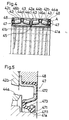
- Fig. 5 which is an enlarged view of a portion A of Fig. 4, each of the sealing devices 47 is configured by integrating a sealing member 471 made of an elastic material such as a synthetic rubber, with an annular core 472.
- a lip 4711 which is in contact with an outer circumference face in the vicinity of an end portion of the inner race 41a (41b) in the circumference direction is formed, and a garter spring (back-up ring) 473 is disposed on the outer circumference of the lip 4711.
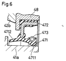
- a sealing device for such a type of rolling bearing known is a device shown in Fig. 6 which is a section view of main portions.
- a sub lip 4712 is formed on the inner side of the lip.
- the sub lip 4712 is configured so as not to be in contact with the inner race 41a (41b) in a normal condition, and exerts the sealing performance due to the labyrinth effect.
- a large amount of rolling water for cooling splashes the surroundings during the use of the rolling bearing.
- the sealing devices of the prior art shown in Figs. 5 and 6 have a sufficient sealing function in such a using environment.
- the sealing devices of the prior art involve a problem in that rolling water easily enters the inside of a bearing. If rolling water enters the inside of a bearing, the lubricity is significantly deteriorated, and the life time is shortened.
- the invention has been conducted in view of the above-mentioned circumstances. It is an object of the invention to provide a sealing device for a rolling bearing in which, when the sealing device is attached to a bearing for a roll neck in a rolling machine, rolling water hardly enters the inside of the bearing as compared with a prior art sealing device, and the life time of the bearing can be therefore improved as compared with the prior art.
- the sealing device for a rolling bearing of the invention is an annular sealing device to be disposed in an end face portion of a bearing for a roll neck in a rolling machine, wherein an outer circumference portion is held on an outer race side, a main lip which is in contact in a circumference direction with an outer circumference face in the vicinity of an end portion of an inner race is formed in an inner circumference portion, a sub lip is protrudingly formed on an axially inner side of the main lip with being separated from the main lip by a predetermined distance, a side face of the sub lip is in contact in a circumference direction with an outer end face of a flange portion in the vicinity of the end portion of the inner race, and an annular grease pool is formed between the sub lip and the main lip.
- the sub lip is disposed on the inner side of the main lip, the sub lip is in contact with the outer end face of the flange portion of the inner race, and the annular grease pool is independently formed between the sub lip and the main lip, thereby suppressing invasion of rolling water.
- the sub lip is positioned on the inner side of the main lip, and the sub and main lips are in contact with the inner race.
- An annular space which is closed to the outside is formed between the lips in cooperation with the inner race.
- the annular space is used as a grease pool, and the inside thereof is filled with grease. Accordingly, rolling water splashing from the outside can enter the inside of the bearing, only after the water passes through all of the contact portion between the main lip and the inner race, the annular grease pool, and the sub lip.
- a sealing device of the prior art which includes only a main lip, or the main lip and a sub lip for producing a labyrinth effect, therefore, the sealing performance against rolling water is greatly improved.
- the sub lip constitutes a so-called face seal in which the side face of the sub lip is in contact with the outer end face of the flange portion of the inner race, so that heat generation and hardening caused by the contact of the sub lip with the inner race can be suppressed.
- Fig. 1 is an axial section view showing the whole configuration of a rolling bearing for a roll neck in a rolling machine to which the sealing device according to the invention is attached
- Fig. 2 is an enlarged view of a portion A in Fig. 1.
- the rolling bearing is a 4-row tapered roller bearing, and structured in a manner equivalent to the roller bearing of the prior art exemplarily shown in Fig. 5.
- the rolling bearing includes two double-raceway inner races 1a and 1b, one double-raceway outer race 2a, and two single-raceway outer races 2b and 2c on both sides thereof.
- a plurality of tapered rollers 3 are disposed in each of four conical raceway tracks formed between these inner and outer races.
- the tapered rollers 3 are held at regular intervals in a circumference direction by cages 4a to 4d in the conical raceways.
- An inner race spacer 5 is interposed between the double-raceway inner races 1a and 1b, and outer race spacers 6a and 6b are interposed between the double-raceway outer race 2a, and the single-raceway outer races 2b and 2c.
- An annular sealing device 7 is attached to each of end portions of the bearing.
- the sealing device 7 is configured by a sealing member 71 made of an elastic member such as a synthetic rubber, an annular core 72 which is integrated with the sealing member, and a garter spring 73.
- An engaging edge 721 which outward protrudes is formed in an outer circumference portion of the core 72. The engaging edge 721 is pressed between the corresponding one of the single-raceway outer races 2b and 2c positioned on both end portions of the bearing, and a sealing cover (flange ring) 8 secured to the corresponding outer end face portion, so that the sealing device 7 is attached to the bearing.
- a main lip 711 is formed on a further outer side than a flange portion 11a (11b) formed in the vicinity of an end portion of the inner race 1a (1b).
- the main lip 711 is in contact with an outer circumference face of the inner race 1a (1b).
- the garter spring 73 is disposed on an outer circumference of the main lip 711.
- a sub lip 712 is formed so as to elongate in parallel to the main lip 711 and to be separated from the main lip by a predetermined distance.
- a side face portion of the sub lip 712 is in contact with the outer end face of the above-mentioned flange portion 11a (11b) of the inner race 1a (1b), thereby constituting a so-called face seal. Since the thickness of the sub lip 712 is very thin as compared with the amount of projection from the main portion of the sealing member 71, the sub lip 712 is extremely softly in contact with the outer end face of the flange portion 11a (11b) of the inner race 1a (1b).
- An annular space elongating in the circumference direction of the bearing is formed between the main lip 711 and the sub lip 712.
- the annular space is used as a grease pool 713. That is, during the work of incorporating the rolling bearing into a roll neck in a rolling machine, an appropriate amount of grease is supplied to the inside of the four conical raceway tracks formed between the inner and outer races, and the grease pool 713 of the sealing device 7 attached to each of the ends of the bearing is filled with grease G.
- the invention is not limited to that which is adopted in the above-mentioned embodiment.
- Fig. 3 which is a section view of main portions of another embodiment of the invention, for example, the following structure may be adopted.
- the stopping edge 721 is not provided, and the core 72 is formed so as to have a substantially U-shaped section, and the outer circumference face of the core 72 is pressingly fitted into the inner circumference face of the sealing cover 8, whereby the core is attached to the bearing.
- a sub lip is formed on an inner side of the main lip with being separated from the main lip by a predetermined distance, a side face of the sub lip is in contact with an outer end face of a flange portion which is formed in the vicinity of the end portion of the inner race, and an annular grease pool is formed between the sub lip and the main lip.
Landscapes
- Engineering & Computer Science (AREA)
- General Engineering & Computer Science (AREA)
- Mechanical Engineering (AREA)
- Sealing Of Bearings (AREA)
- Rolling Contact Bearings (AREA)
- Sealing With Elastic Sealing Lips (AREA)
Abstract
Description
Claims (1)
- A sealing device for a rolling bearing which is an annular sealing device to be disposed in an end face portion of a bearing for a roll neck in a rolling machine, wherein an outer circumference portion is held on an outer race side, a main lip which is in contact in a circumference direction an outer circumference face in the vicinity of an end portion of an inner race is formed in an inner circumference portion, a sub lip is protrudingly formed on an axially inner side of said main lip with being directed in an inner circumference direction and separated from said main lip by a predetermined distance, a side face of said sub lip is in contact in a circumference direction with an outer end face of a flange portion in the vicinity of the end portion of the inner race, and an annular grease pool is formed between said sub lip and said main lip.
Applications Claiming Priority (2)
| Application Number | Priority Date | Filing Date | Title |
|---|---|---|---|
| JP19117099 | 1999-07-06 | ||
| JP11191170A JP2001020962A (en) | 1999-07-06 | 1999-07-06 | Sealing device for rolling bearing |
Publications (3)
| Publication Number | Publication Date |
|---|---|
| EP1067301A2 true EP1067301A2 (en) | 2001-01-10 |
| EP1067301A3 EP1067301A3 (en) | 2001-02-28 |
| EP1067301B1 EP1067301B1 (en) | 2003-10-01 |
Family
ID=16270075
Family Applications (1)
| Application Number | Title | Priority Date | Filing Date |
|---|---|---|---|
| EP00114295A Expired - Lifetime EP1067301B1 (en) | 1999-07-06 | 2000-07-04 | Sealing device for a rolling bearing |
Country Status (4)
| Country | Link |
|---|---|
| EP (1) | EP1067301B1 (en) |
| JP (1) | JP2001020962A (en) |
| DE (1) | DE60005607T2 (en) |
| ES (1) | ES2208189T3 (en) |
Families Citing this family (4)
| Publication number | Priority date | Publication date | Assignee | Title |
|---|---|---|---|---|
| JP2005133885A (en) * | 2003-10-31 | 2005-05-26 | Ntn Corp | Bearing with sealing device |
| JP5143718B2 (en) * | 2008-12-25 | 2013-02-13 | 住友重機械工業株式会社 | Rotating device |
| JP2014173686A (en) * | 2013-03-11 | 2014-09-22 | Nsk Ltd | Sealed roll neck bearing |
| CN107906210A (en) * | 2017-12-08 | 2018-04-13 | 四川煤田地质局四机械厂 | A kind of sealing device and encapsulating method |
Family Cites Families (15)
| Publication number | Priority date | Publication date | Assignee | Title |
|---|---|---|---|---|
| BE543293A (en) * | 1954-12-10 | |||
| FR2259284B2 (en) * | 1974-01-28 | 1981-05-22 | Roulements Soc Nouvelle | |
| JPS54158556A (en) * | 1978-06-05 | 1979-12-14 | Nippon Seiko Kk | Bearing seal mechanism loosely fitted to shaft |
| FR2505951A1 (en) * | 1981-05-13 | 1982-11-19 | Roulements Soc Nouvelle | ROTATING SEAL BETWEEN COAXIAL PARTS WITH METAL MOUNTING FRAME |
| DE3414008C2 (en) * | 1984-04-13 | 1986-03-13 | Fa. Carl Freudenberg, 6940 Weinheim | Cassette seal |
| JPH0686909B2 (en) * | 1987-11-23 | 1994-11-02 | ザ ティムケン カンパニー | Small seal |
| JPH03114U (en) * | 1989-05-23 | 1991-01-07 | ||
| IT1240465B (en) * | 1990-05-24 | 1993-12-17 | Skf Ind Spa | SEALING DEVICE FOR BEARINGS OF VEHICLE WHEEL HUBS. |
| US5129744A (en) * | 1991-06-17 | 1992-07-14 | The Timken Company | Two component bearing seal with bumpers |
| JPH0586031U (en) * | 1992-04-23 | 1993-11-19 | 光洋精工株式会社 | Multi-row rolling bearing device |
| DE4312364A1 (en) * | 1993-04-16 | 1994-10-20 | Schaeffler Waelzlager Kg | Radial rolling-contact bearing |
| JPH07332379A (en) * | 1994-06-10 | 1995-12-22 | Ntn Corp | Sealing device for deep groove ball bearing |
| JPH09329148A (en) * | 1996-06-05 | 1997-12-22 | Nippon Seiko Kk | Sealed rolling bearing |
| DE19709056B4 (en) * | 1997-03-06 | 2006-01-26 | Ina-Schaeffler Kg | Seal for a clutch release bearing |
| JPH10252762A (en) * | 1997-03-12 | 1998-09-22 | Nippon Seiko Kk | Sealing device for rolling bearings |
-
1999
- 1999-07-06 JP JP11191170A patent/JP2001020962A/en active Pending
-
2000
- 2000-07-04 ES ES00114295T patent/ES2208189T3/en not_active Expired - Lifetime
- 2000-07-04 DE DE60005607T patent/DE60005607T2/en not_active Expired - Lifetime
- 2000-07-04 EP EP00114295A patent/EP1067301B1/en not_active Expired - Lifetime
Also Published As
| Publication number | Publication date |
|---|---|
| DE60005607T2 (en) | 2004-04-29 |
| JP2001020962A (en) | 2001-01-23 |
| EP1067301A3 (en) | 2001-02-28 |
| EP1067301B1 (en) | 2003-10-01 |
| ES2208189T3 (en) | 2004-06-16 |
| DE60005607D1 (en) | 2003-11-06 |
Similar Documents
| Publication | Publication Date | Title |
|---|---|---|
| US3639016A (en) | Rolling contact bearing seals | |
| US4505484A (en) | Sealing device for a rolling bearing | |
| KR102153439B1 (en) | Rolling bearing device, and backup roll for rolling mill including the rolling bearing device | |
| US3951482A (en) | Unitized thrust bearing and seal assembly | |
| JP2017166532A (en) | Ball bearing | |
| JP2005076660A (en) | Rolling bearing device | |
| JP2010190241A (en) | Self-aligning roller bearing | |
| US4049328A (en) | Subassembly cartridge for sealing and adjusting bearing assemblies | |
| EP1067301B1 (en) | Sealing device for a rolling bearing | |
| JPH08270663A (en) | Automatic alignment rolling bearing with seal | |
| JP5781318B2 (en) | Slewing bearing seal structure | |
| JPH0712736Y2 (en) | Spherical roller bearing | |
| JP2001032846A (en) | Sealed rolling bearing | |
| JP7491134B2 (en) | Rolling bearings | |
| JP2015183794A (en) | sealing device | |
| US20090041400A1 (en) | Rolling bearing apparatus | |
| JP2992735B2 (en) | Bearing sealing device | |
| WO2008050755A1 (en) | Sealing device | |
| JP2016001036A (en) | Sealed rolling bearing | |
| JP5274931B2 (en) | Double row roller bearing | |
| JP2015227671A (en) | Sealing-type rolling bearing | |
| JPH0516410Y2 (en) | ||
| JP2005233341A (en) | Double-row conical roller bearing device | |
| JPS6139874Y2 (en) | ||
| JPH11254010A (en) | Hermetically sealing device for roll neck bearing of rolling mill |
Legal Events
| Date | Code | Title | Description |
|---|---|---|---|
| PUAI | Public reference made under article 153(3) epc to a published international application that has entered the european phase |
Free format text: ORIGINAL CODE: 0009012 |
|
| AK | Designated contracting states |
Kind code of ref document: A2 Designated state(s): DE ES FR IT |
|
| AX | Request for extension of the european patent |
Free format text: AL;LT;LV;MK;RO;SI |
|
| PUAL | Search report despatched |
Free format text: ORIGINAL CODE: 0009013 |
|
| AK | Designated contracting states |
Kind code of ref document: A3 Designated state(s): AT BE CH CY DE DK ES FI FR GB GR IE IT LI LU MC NL PT SE |
|
| AX | Request for extension of the european patent |
Free format text: AL;LT;LV;MK;RO;SI |
|
| RIC1 | Information provided on ipc code assigned before grant |
Free format text: 7F 16C 33/78 A |
|
| 17P | Request for examination filed |
Effective date: 20010315 |
|
| 17Q | First examination report despatched |
Effective date: 20010424 |
|
| AKX | Designation fees paid |
Free format text: DE ES FR IT |
|
| RIC1 | Information provided on ipc code assigned before grant |
Free format text: 7F 16C 33/78 A |
|
| GRAH | Despatch of communication of intention to grant a patent |
Free format text: ORIGINAL CODE: EPIDOS IGRA |
|
| RIC1 | Information provided on ipc code assigned before grant |
Ipc: 7F 16C 33/78 A |
|
| GRAH | Despatch of communication of intention to grant a patent |
Free format text: ORIGINAL CODE: EPIDOS IGRA |
|
| GRAA | (expected) grant |
Free format text: ORIGINAL CODE: 0009210 |
|
| AK | Designated contracting states |
Kind code of ref document: B1 Designated state(s): DE ES FR IT |
|
| REF | Corresponds to: |
Ref document number: 60005607 Country of ref document: DE Date of ref document: 20031106 Kind code of ref document: P |
|
| ET | Fr: translation filed | ||
| REG | Reference to a national code |
Ref country code: ES Ref legal event code: FG2A Ref document number: 2208189 Country of ref document: ES Kind code of ref document: T3 |
|
| PLBE | No opposition filed within time limit |
Free format text: ORIGINAL CODE: 0009261 |
|
| STAA | Information on the status of an ep patent application or granted ep patent |
Free format text: STATUS: NO OPPOSITION FILED WITHIN TIME LIMIT |
|
| 26N | No opposition filed |
Effective date: 20040702 |
|
| PGFP | Annual fee paid to national office [announced via postgrant information from national office to epo] |
Ref country code: ES Payment date: 20080808 Year of fee payment: 9 |
|
| PGFP | Annual fee paid to national office [announced via postgrant information from national office to epo] |
Ref country code: IT Payment date: 20080729 Year of fee payment: 9 |
|
| REG | Reference to a national code |
Ref country code: ES Ref legal event code: FD2A Effective date: 20090706 |
|
| PG25 | Lapsed in a contracting state [announced via postgrant information from national office to epo] |
Ref country code: ES Free format text: LAPSE BECAUSE OF NON-PAYMENT OF DUE FEES Effective date: 20090706 |
|
| PG25 | Lapsed in a contracting state [announced via postgrant information from national office to epo] |
Ref country code: IT Free format text: LAPSE BECAUSE OF NON-PAYMENT OF DUE FEES Effective date: 20090704 |
|
| PGFP | Annual fee paid to national office [announced via postgrant information from national office to epo] |
Ref country code: FR Payment date: 20110727 Year of fee payment: 12 |
|
| PGFP | Annual fee paid to national office [announced via postgrant information from national office to epo] |
Ref country code: DE Payment date: 20120627 Year of fee payment: 13 |
|
| REG | Reference to a national code |
Ref country code: FR Ref legal event code: ST Effective date: 20130329 |
|
| PG25 | Lapsed in a contracting state [announced via postgrant information from national office to epo] |
Ref country code: FR Free format text: LAPSE BECAUSE OF NON-PAYMENT OF DUE FEES Effective date: 20120731 |
|
| PG25 | Lapsed in a contracting state [announced via postgrant information from national office to epo] |
Ref country code: DE Free format text: LAPSE BECAUSE OF NON-PAYMENT OF DUE FEES Effective date: 20140201 |
|
| REG | Reference to a national code |
Ref country code: DE Ref legal event code: R119 Ref document number: 60005607 Country of ref document: DE Effective date: 20140201 |