EP1067217A1 - Method and apparatus for protecting alkali chloride electrolytic cell - Google Patents
Method and apparatus for protecting alkali chloride electrolytic cell Download PDFInfo
- Publication number
- EP1067217A1 EP1067217A1 EP00114526A EP00114526A EP1067217A1 EP 1067217 A1 EP1067217 A1 EP 1067217A1 EP 00114526 A EP00114526 A EP 00114526A EP 00114526 A EP00114526 A EP 00114526A EP 1067217 A1 EP1067217 A1 EP 1067217A1
- Authority
- EP
- European Patent Office
- Prior art keywords
- gas
- cathode
- chamber
- gas diffusion
- electrolytic cell
- Prior art date
- Legal status (The legal status is an assumption and is not a legal conclusion. Google has not performed a legal analysis and makes no representation as to the accuracy of the status listed.)
- Withdrawn
Links
Images
Classifications
-
- C—CHEMISTRY; METALLURGY
- C25—ELECTROLYTIC OR ELECTROPHORETIC PROCESSES; APPARATUS THEREFOR
- C25B—ELECTROLYTIC OR ELECTROPHORETIC PROCESSES FOR THE PRODUCTION OF COMPOUNDS OR NON-METALS; APPARATUS THEREFOR
- C25B15/00—Operating or servicing cells
-
- C—CHEMISTRY; METALLURGY
- C25—ELECTROLYTIC OR ELECTROPHORETIC PROCESSES; APPARATUS THEREFOR
- C25B—ELECTROLYTIC OR ELECTROPHORETIC PROCESSES FOR THE PRODUCTION OF COMPOUNDS OR NON-METALS; APPARATUS THEREFOR
- C25B1/00—Electrolytic production of inorganic compounds or non-metals
- C25B1/01—Products
- C25B1/34—Simultaneous production of alkali metal hydroxides and chlorine, oxyacids or salts of chlorine, e.g. by chlor-alkali electrolysis
- C25B1/46—Simultaneous production of alkali metal hydroxides and chlorine, oxyacids or salts of chlorine, e.g. by chlor-alkali electrolysis in diaphragm cells
-
- C—CHEMISTRY; METALLURGY
- C25—ELECTROLYTIC OR ELECTROPHORETIC PROCESSES; APPARATUS THEREFOR
- C25B—ELECTROLYTIC OR ELECTROPHORETIC PROCESSES FOR THE PRODUCTION OF COMPOUNDS OR NON-METALS; APPARATUS THEREFOR
- C25B11/00—Electrodes; Manufacture thereof not otherwise provided for
- C25B11/02—Electrodes; Manufacture thereof not otherwise provided for characterised by shape or form
- C25B11/03—Electrodes; Manufacture thereof not otherwise provided for characterised by shape or form perforated or foraminous
- C25B11/031—Porous electrodes
- C25B11/032—Gas diffusion electrodes
Definitions
- This invention relates to a method and an apparatus for protecting an alkali chloride electrolytic cell. More particularly, it relates to a method and an apparatus for protecting an alkali chloride electrolytic cell having a gas diffusion cathode, in which an alkali chloride aqueous solution is electrolyzed to produce chlorine and a caustic alkali, against performance reduction while the cell is in a suspended state.
- a method for electrolytically obtaining a caustic alkali from an alkali chloride aqueous solution by an ion-exchange membrane method which uses a gas diffusion cathode is known.
- This method is achieved with an electrolysis cell partitioned with an ion-exchange membrane, usually a cation-exchange membrane, into an anode chamber having an anode and containing an alkali chloride aqueous solution and a cathode chamber having a gas diffusion cathode and containing water or a caustic alkali aqueous solution, and electricity is passed between the two electrodes to electrolyze the alkali chloride aqueous solution.
- the gas diffusion cathode is made of a porous material and supplied with an oxygen-containing gas to carry out electrolysis to obtain a caustic alkali in the cathode chamber.
- the merit of this technique consists in that hydrogen gas does not generate on the cathode so that the requisite electrolytic voltage is markedly reduced.
- JP-A-54-97600 (The term "JP-A” used herein means an “unexamined published Japanese patent application"), JP-A-56-44784, JP-A-56-130482, JP-A-57-152479, JP-A-59-133386, JP-A-61-266591, JP-B-58-44156 (The term “JP-B” used herein means an "examined Japanese patent publication”), JP-B-58-49639, JP-B-60-9595, and JP-B-61-20634.
- JP-A-60-221595 teaches a method comprising diluting or displacing the electrolytic solution in the cell with water on the occasion of suspension
- JP-A-5-255882 proposes filling the cathode chamber with water or an aqueous caustic alkali saturated with hydrogen gas during suspension.
- the present inventors have ascertained that these techniques are effective in protecting a gas diffusion cathode but, in turn, involve not a few problems.
- JP-A-60-221595 which comprises dilution or displacement of the electrolytic solution in a cell with water entertains a fear of reducing the performance of the ion-exchange membrane.
- the method taught in JP-A-5-255882 which comprises filling the cathode chamber with hydrogen-saturated water or aqueous caustic alkali is followed, there is a great possibility that hydrogen gas remaining inside the gas diffusion cathode, which is permeable to gas, and the oxygen-containing gas filling the gas chamber are mixed up to form detonating gas. This system has also turned out to be problematical in the practice.
- the cell is partitioned with an ion-exchange membrane into an anode chamber having an anode and a cathode chamber having a cathode, and an alkali chloride aqueous solution is fed to the anode chamber, where electrolysis is conducted to produce chlorine gas, while an aqueous caustic alkali or water is fed to the cathode chamber, where a caustic alkali and hydrogen gas are produced.
- the anode is noble compared with the chlorine generating potential by the chlorine overvoltage, while the cathode is less noble than the hydrogen generating potential by the hydrogen overvoltage.
- the electrolytic cell to be used in this system is constructed of materials which can stand such voltage-potential conditions.
- the anode chamber is generally made up of titanium, and the anode comprises a titanium base coated with a catalyst for chlorine evolution, such as a noble metal, e.g., platinum, ruthenium, iridium, palladium or rhodium, or an oxide thereof.
- a catalyst for chlorine evolution such as a noble metal, e.g., platinum, ruthenium, iridium, palladium or rhodium, or an oxide thereof.
- the cathode chamber is made of nickel or high grade stainless steel.
- the cathode comprises a nickel or high grade stainless steel base coated with a catalyst for hydrogen evolution.
- the anode is noble over the chlorine generating potential by the chlorine overvoltage as far as the cell is ordinarily operated. This is the same as in the case of the electrolysis using no gas diffusion electrode.
- the gas diffusion cathode is less noble than the oxygen reducing potential by the overvoltage.
- the chlorine generating reaction and the oxygen reducing reaction cease, but the potential of the anode and the anode chamber is maintained at the chlorine generating potential because the anolyte, i.e., the alkali chloride aqueous solution contains dissolved chlorine, and the gas diffusion cathode and the cathode chamber are kept at the oxygen reducing potential since the gas diffusion cathode is in contact with the caustic alkali aqueous solution and oxygen gas.
- the anode reactions are totally the same.
- the anode and the anode chamber of the electrolytic cell having a gas diffusion electrode can be made of the same materials as conventionally used for those of the cell having no gas diffusion cathode.
- the cathode reactions are largely different between the two systems.
- JP-B-58-49639 proposes use of silver obtained by pyrolysis of a silver carboxylate as a catalyst.
- JP-A-10-158877 discloses using silver or a silver alloy for joining a conductive porous body with a gas diffusion cathode and a gas chamber. According to the teaching of JP-A-10-158878, the conductive porous body joined to the gas diffusion cathode can be made of sponge nickel coated with silver.
- the present inventors have extensively studied on a method for producing chlorine and a caustic alkali by electrolyzing an alkali chloride aqueous solution in an electrolytic cell having a gas diffusion cathode, particularly a countermeasure against corrosion of the gas diffusion cathode and the cathode chamber while the operation of the cell is suspended. They have found as a result that the above objects of the invention can be achieved by providing the following methods and apparatus.
- Alkali chloride electrolysis by the ion-exchange membrane method using a gas diffusion cathode involves a cathode reaction in which oxygen and water participate as represented by formula: 1/4O 2 + 1/2H 2 O + e ⁇ OH -
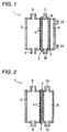
- FIG. 1 An example of the electrolytic cell by the ion-exchange membrane method using a gas diffusion cathode is schematically illustrated in Fig. 1.
- the electrolytic cell 1 shown in Fig. 1 is partitioned with an ion-exchange membrane 2 into an anode side and a cathode side.
- the whole on the anode side serves as an anode chamber 3, which has an anode 4 having a large number of openings in intimate contact with the ion-exchange membrane 2, an anolyte feed opening 5 at the bottom, and an anolyte discharge opening 6 at the top.
- the cathode side of the ion-exchange membrane 2 is partitioned with a gas diffusion cathode 7 into a cathode chamber 8 on the ion-exchange membrane 2 side and a gas chamber 9 on the opposite side.
- the cathode chamber 8 has a caustic solution feed opening 10 at the bottom and a caustic solution discharge opening 11 at the top.
- the gas chamber 9 has a gas feed opening 12 at the upper part and a gas discharge opening 13 at the lower part.
- the mechanism of the anode chamber 3 is, in principle, the same as in the electrolytic cell by the ordinary ion-exchange membrane method using no gas diffusion cathode 7.
- An alkali chloride aqueous solution is supplied from the anolyte feed opening 5.
- the alkali chloride aqueous solution is electrolyzed to form chlorine gas and alkali metal ions and reduces its concentration.
- the produced chlorine gas and the thus thinned aqueous solution of the alkali chloride are discharged from the anolyte discharge opening 6.
- the alkali metal ions generated on the anode 4 pass through the ion-exchange membrane 2 into the cathode chamber 8.
- a caustic alkali aqueous solution or water is fed to the caustic solution feed opening 10 and brought into contact with the gas diffusion cathode 7, while an oxygen-containing gas is fed to the gas diffusion cathode 7 from the gas chamber 9.
- the electrolytic reaction according to the formula shown above takes place on the surface of the gas diffusion cathode 7.
- the hydroxyl ions produced react with the alkali metal ions having penetrated through the ion-exchange membrane 2 to form a caustic alkali, which is discharged from the caustic solution discharge opening 11.
- the caustic alkali aqueous solution or water fed through the caustic solution feed opening 10 increases the alkali concentration and is then discharged from the caustic solution discharge opening 11.
- An oxygen-containing gas is fed from the gas feed opening 12 to the gas chamber 9 which is adjacent to the gas diffusion cathode 7 on the side opposite to the cathode chamber 8. Part of the oxygen participates in the reaction, and the rest is discharged from the gas discharge opening 13.
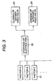
- Fig. 2 schematically illustrates an example of two-chamber type electrolytic cell by the ion-exchange membrane method using a gas diffusion cathode 7, in which an ion-exchange membrane 2 is provided to partition the cell into an anode chamber 3 and a cathode chamber 2.
- An anode 4 having a large number of openings is provided in the anode chamber 3 in intimate contact with the partitioning ion-exchange membrane 2.
- a gas diffusion cathode 7 is provided on the opposite side of the ion-exchange membrane 2 with a spacer (not shown) interposed therebetween.
- the anode chamber 3 has an anolyte feed opening 5 at the bottom and an anolyte discharge opening 6 at the top.
- the cathode chamber 8 has a gas/water feed opening 14 at the top and a caustic solution/exhaust gas discharge opening 15 at the bottom.
- the principle of the anode chamber 3 is the same as in the three chamber type cell shown in Fig. 1.
- the gas diffusion cathode 7 is disposed in contact with the ion-exchange membrane 2, and the cathode chamber 8 also serves as a gas chamber.
- An oxygen-containing gas and water are fed to the cathode chamber 8 from the gas/water feed opening 14.
- Part of the water is electrolyzed in according the reaction formula shown above on the surface of the gas diffusion cathode 7.
- the produced hydroxyl ions react with the alkali metal ions having passed through the ion-exchange membrane 2 to form a caustic alkali, which is discharged from the caustic solution/gas discharge opening 15 in the form of an aqueous solution together with the exhaust gas.
- the concentration of the caustic alkali aqueous solution is adjusted with water fed from the gas/water feed opening 14.
- the electrolysis by the ion-exchange membrane method using a gas diffusion electrode include a few systems.
- the present invention is suitably applicable to whichever system as long as an oxygen reduction reaction is conducted in a caustic alkali.
- the gas diffusion cathode 7 used in the present invention can be any of various types proposed to date which comprise metal. Typical is a porous gas-permeable sheet prepared by hot pressing a mixture of carbon powder and polytetrafluoroethylene (PTFE) and having supported thereon a noble metal, such as platinum or silver or an alloy thereof, as a catalyst.
- PTFE polytetrafluoroethylene
- the gas diffusion cathode may be combined with a metallic mesh to have increased strength or increased conductivity.
- Nickel is usually used as a material forming the cathode chamber 8. Nickel coated with silver, etc. can be used to enhance anticorrosion. In the three-chamber type cell shown in Fig. 1, while no liquid flows basically in the gas chamber 9, should there be the possibility of the caustic alkali solution's leaking, considerations for anticorrosion is necessary.
- the potential of the gas diffusion cathode 7 is less noble than the oxygen reducing potential by the overvoltage.
- the overvoltage is eliminated so that the potential is equal to the oxygen reducing potential and is noble as compared with the potential during electrolysis. If oxygen gas exists under such a condition, it is assumed that the gas diffusion cathode 7 is deteriorated and that the cathode chamber 8 is corroded.
- Automatic gas displacement can preferably be effected by fitting the electrolytic cell 1 with an apparatus comprising a first sensor which detects factors for stopping the cell 1 (taken as factors A, B, C%) and emits a factor signal, an automatic stopping device which stops the operation of the cell and closes the oxygen-containing gas feed valve on receipt of the factor signal, a second sensor which confirms the closure of the oxygen-containing gas feed valve and emits a closure confirming signal, and an inert gas release device which feeds an inert gas into the gas chamber on receipt of the closure confirming signal.
- a first sensor which detects factors for stopping the cell 1 (taken as factors A, B, C8) and emits a factor signal
- an automatic stopping device which stops the operation of the cell and closes the oxygen-containing gas feed valve on receipt of the factor signal
- a second sensor which confirms the closure of the oxygen-containing gas feed valve and emits a closure confirming signal
- an inert gas release device which feeds an inert gas into the gas chamber on receipt of the closure
- the instrumentation block flowsheet of the above-described embodiment is shown in Fig. 3.
- the operation of the electrolytic cell 1 is stopped (block 22) on receipt of signals based on factor 21 for the stoppage.
- the oxygen feed valve of the oxygen-containing gas feed pipe is closed (block 23) and, at the same time, a nitrogen feed valve which is connected to the same pipe is opened (block 24). All these operations are automated.
- the above-mentioned automatic system makes it possible to prevent the gas diffusion cathode from deterioration and the cathode chamber from corrosion while electrolysis is suspended whereby the electrolytic cell can maintain the initial performance for an extended period of time.
- Electrolysis of sodium chloride was carried out under the conditions shown below for successive 126 days. During the running test, the electrolysis was suspended after 9, 11, 12, 13, 16, 18, 23, 27, and 97 days by ceasing the oxygen gas feed and displacing with nitrogen. No abnormalities was found in the gas diffusion cathode after the 126 day electrolysis. Changes in electrolytic voltage and gas diffusion cathode overvoltage with time are shown in Table 1 below.
- the gas diffusion cathode used in the cell was prepared by hot pressing into one body a gas diffusion layer made of 60 wt% of hydrophobic carbon black (acetylene black produced by Denki Kagaku Kogyo K.K.) and 40 wt% of polytetrafluoroethylene (PTFE) (D-1, available from Daikin Industries, Ltd.), a reaction layer made of 20 parts by weight of hydrophilic carbon black (AB-12, available from Denki Kagaku Kogyo K.K.) and 10 parts by weight of PTFE, and a silver mesh as a current collector, and applying thereto 3 mg/cm 2 of silver as a catalyst.
- Electrolysis was carried out under the same conditions as in Example 1, except that the operation was suspended once on the 7th day for 10 hours during which oxygen was kept flowing and then resumed.
- the electrolytic voltage and the gas diffusion cathode overvoltage before the suspension (on the 6th day of running) were 2.18 V and 0.54 V, respectively, and those after the suspension (on the 8th day) were 2.24 V and 0.59 V, respectively.
- the electrolytic voltage and the gas diffusion cathode overvoltage were 2.25 V and 0.60 V, respectively, showing no restoration.
- the circulating caustic alkali solution was found slightly green-tinged, which is assumed ascribed to nickel dissolved out of the cathode chamber.
- the present invention provides a method and an apparatus for protecting an alkali chloride electrolytic cell having a gas diffusion cathode, by which the gas diffusion cathode is prevented from being deteriorated and the cathode chamber is prevented from being corroded while the operation of the cell is suspended thereby to maintain the initial performance of the cell for an extended period of time.
Landscapes
- Chemical & Material Sciences (AREA)
- Engineering & Computer Science (AREA)
- Chemical Kinetics & Catalysis (AREA)
- Electrochemistry (AREA)
- Materials Engineering (AREA)
- Metallurgy (AREA)
- Organic Chemistry (AREA)
- Inorganic Chemistry (AREA)
- Electrolytic Production Of Non-Metals, Compounds, Apparatuses Therefor (AREA)
Abstract
A method of protecting an alkali chloride electrolytic cell having a gas diffusion cathode, which comprises, on the occasion when the operation of the electrolytic cell is suspended: stopping feed of an oxygen-containing gas to a gas chamber of the cell; and substantially displacing an oxygen-containing gas atmosphere of the gas chamber with an inert gas atmosphere. Also disclosed is an apparatus for carrying out the method.
Description
This invention relates to a method and an apparatus
for protecting an alkali chloride electrolytic cell. More
particularly, it relates to a method and an apparatus for
protecting an alkali chloride electrolytic cell having a gas
diffusion cathode, in which an alkali chloride aqueous
solution is electrolyzed to produce chlorine and a caustic
alkali, against performance reduction while the cell is in a
suspended state.
A method for electrolytically obtaining a caustic
alkali from an alkali chloride aqueous solution by an ion-exchange
membrane method which uses a gas diffusion cathode
is known. This method is achieved with an electrolysis cell
partitioned with an ion-exchange membrane, usually a cation-exchange
membrane, into an anode chamber having an anode and
containing an alkali chloride aqueous solution and a cathode
chamber having a gas diffusion cathode and containing water
or a caustic alkali aqueous solution, and electricity is
passed between the two electrodes to electrolyze the alkali
chloride aqueous solution. The gas diffusion cathode is
made of a porous material and supplied with an oxygen-containing
gas to carry out electrolysis to obtain a caustic
alkali in the cathode chamber. The merit of this technique
consists in that hydrogen gas does not generate on the
cathode so that the requisite electrolytic voltage is
markedly reduced.
Documents disclosing the above-mentioned
electrolysis method includes JP-A-54-97600 (The term "JP-A"
used herein means an "unexamined published Japanese patent
application"), JP-A-56-44784, JP-A-56-130482, JP-A-57-152479,
JP-A-59-133386, JP-A-61-266591, JP-B-58-44156 (The term "JP-B"
used herein means an "examined Japanese patent
publication"), JP-B-58-49639, JP-B-60-9595, and JP-B-61-20634.
While a number of proposals have hitherto been made
with respect to improvement on the production method, or the
performance, of a gas diffusion cathode, there are only a
few on prevention of reduction in performance of a gas
diffusion cathode while the operation is suspended. For
example, JP-A-60-221595 teaches a method comprising diluting
or displacing the electrolytic solution in the cell with
water on the occasion of suspension, and JP-A-5-255882
proposes filling the cathode chamber with water or an
aqueous caustic alkali saturated with hydrogen gas during
suspension. The present inventors have ascertained that
these techniques are effective in protecting a gas diffusion
cathode but, in turn, involve not a few problems.
Specifically, the method of JP-A-60-221595 which
comprises dilution or displacement of the electrolytic
solution in a cell with water entertains a fear of reducing
the performance of the ion-exchange membrane. Where the
method taught in JP-A-5-255882 which comprises filling the
cathode chamber with hydrogen-saturated water or aqueous
caustic alkali is followed, there is a great possibility
that hydrogen gas remaining inside the gas diffusion cathode,
which is permeable to gas, and the oxygen-containing gas
filling the gas chamber are mixed up to form detonating gas.
This system has also turned out to be problematical in the
practice.
In order to operate an electrolytic cell by the ion-exchange
membrane method using a gas diffusion cathode for a
long period of time while maintaining the initial
performance, it is important not only to set optimum
conditions of operation but to optimize the state of the
cell during suspension of operation. A bad treatment during
the suspension could result in considerable reduction of the
cell performance, sometimes making the cell useless.
In the case of alkali chloride electrolysis by the
ion-exchange membrane method using no gas diffusion cathode,
on the other hand, the cell is partitioned with an ion-exchange
membrane into an anode chamber having an anode and
a cathode chamber having a cathode, and an alkali chloride
aqueous solution is fed to the anode chamber, where
electrolysis is conducted to produce chlorine gas, while an
aqueous caustic alkali or water is fed to the cathode
chamber, where a caustic alkali and hydrogen gas are
produced. Accordingly, during ordinary operation, the anode
is noble compared with the chlorine generating potential by
the chlorine overvoltage, while the cathode is less noble
than the hydrogen generating potential by the hydrogen
overvoltage.
On stopping the electrolytic cell, evolution of both
chlorine and hydrogen also cease. In this state, the
anolyte, an alkali chloride aqueous solution, has dissolved
therein chlorine, and the catholyte, i.e., a caustic alkali
aqueous solution has dissolved therein hydrogen. As a
result, the anode and the anode chamber are kept at the
chlorine generating potential, and the cathode and the
cathode chamber are maintained at the hydrogen generating
potential. The electrolytic cell to be used in this system
is constructed of materials which can stand such voltage-potential
conditions. Specifically, the anode chamber is
generally made up of titanium, and the anode comprises a
titanium base coated with a catalyst for chlorine evolution,
such as a noble metal, e.g., platinum, ruthenium, iridium,
palladium or rhodium, or an oxide thereof. The cathode
chamber is made of nickel or high grade stainless steel.
The cathode comprises a nickel or high grade stainless steel
base coated with a catalyst for hydrogen evolution.
In the alkali chloride electrolytic cell having a
gas diffusion cathode, the anode is noble over the chlorine
generating potential by the chlorine overvoltage as far as
the cell is ordinarily operated. This is the same as in the
case of the electrolysis using no gas diffusion electrode.
On the other hand, the gas diffusion cathode is less noble
than the oxygen reducing potential by the overvoltage. Upon
stopping the cell operation, the chlorine generating
reaction and the oxygen reducing reaction cease, but the
potential of the anode and the anode chamber is maintained
at the chlorine generating potential because the anolyte,
i.e., the alkali chloride aqueous solution contains
dissolved chlorine, and the gas diffusion cathode and the
cathode chamber are kept at the oxygen reducing potential
since the gas diffusion cathode is in contact with the
caustic alkali aqueous solution and oxygen gas.
Comparing these two electrolysis systems, the anode
reactions are totally the same. In other words, the anode
and the anode chamber of the electrolytic cell having a gas
diffusion electrode can be made of the same materials as
conventionally used for those of the cell having no gas
diffusion cathode. However, the cathode reactions are
largely different between the two systems.
The metallic materials commonly employed to
construct the cathode and the cathode chamber of a
conventional ion-exchange method electrolytic cell having no
gas diffusion cathode, such as nickel and stainless steel,
have been regarded as being more susceptible to corrosion
and having poor durability for long-term operation where
used as the gas diffusion cathode or the cathode chamber.
Since silver is generally more resistant to
corrosion than nickel or stainless steel and not so
expensive as other noble metals, it has been attracting
attention as a material that hardly corrodes and can
withstand long use even under an oxidizing environment. JP-B-58-49639
proposes use of silver obtained by pyrolysis of a
silver carboxylate as a catalyst. JP-A-10-158877 discloses
using silver or a silver alloy for joining a conductive
porous body with a gas diffusion cathode and a gas chamber.
According to the teaching of JP-A-10-158878, the conductive
porous body joined to the gas diffusion cathode can be made
of sponge nickel coated with silver.
As long as the electrolytic cell having a gas
diffusion cathode is in operation, it is true that silver is
sufficiently anti-corrosive as a material making the gas
diffusion cathode and the cathode chamber. Even when nickel
is used, the degree of corrosion is not so notable.
According to the present inventors' study, however, it has
turned out that either silver or nickel has poor resistance
to corrosion in the suspended state of the cell. Seeing the
case where silver is used as a catalyst, it may exert a
fatal influence for silver to have poor anti-corrosion.
Cases are sometimes met with in which even a noble metal,
such as platinum, which may be used as a catalyst of a gas
diffusion cathode, is corroded at an oxygen reducing
potential.
It is therefore an object of the present invention
to provide a method and an apparatus for protecting an
alkali chloride electrolytic cell having a gas diffusion
cathode which is used to electrolyze an alkali chloride
aqueous solution to produce chlorine and a caustic alkali,
by which deterioration of the gas diffusion cathode and
corrosion of the cathode chamber are prevented while the
operation of the cell is suspended thereby to maintain the
initial performance of the cell for an extended period of
time.
Other objects and effects of the present invention
will become apparent from the following description.
The present inventors have extensively studied on a
method for producing chlorine and a caustic alkali by
electrolyzing an alkali chloride aqueous solution in an
electrolytic cell having a gas diffusion cathode,
particularly a countermeasure against corrosion of the gas
diffusion cathode and the cathode chamber while the
operation of the cell is suspended. They have found as a
result that the above objects of the invention can be
achieved by providing the following methods and apparatus.
Alkali chloride electrolysis by the ion-exchange
membrane method using a gas diffusion cathode involves a
cathode reaction in which oxygen and water participate as
represented by formula:
1/4O2 + 1/2H2O + e → OH-
An example of the electrolytic cell by the ion-exchange
membrane method using a gas diffusion cathode is
schematically illustrated in Fig. 1. The electrolytic cell
1 shown in Fig. 1 is partitioned with an ion-exchange
membrane 2 into an anode side and a cathode side. The whole
on the anode side serves as an anode chamber 3, which has an
anode 4 having a large number of openings in intimate
contact with the ion-exchange membrane 2, an anolyte feed
opening 5 at the bottom, and an anolyte discharge opening 6
at the top. The cathode side of the ion-exchange membrane 2
is partitioned with a gas diffusion cathode 7 into a cathode
chamber 8 on the ion-exchange membrane 2 side and a gas
chamber 9 on the opposite side. The cathode chamber 8 has a
caustic solution feed opening 10 at the bottom and a caustic
solution discharge opening 11 at the top. The gas chamber 9
has a gas feed opening 12 at the upper part and a gas
discharge opening 13 at the lower part.
The mechanism of the anode chamber 3 is, in
principle, the same as in the electrolytic cell by the
ordinary ion-exchange membrane method using no gas diffusion
cathode 7. An alkali chloride aqueous solution is supplied
from the anolyte feed opening 5. On contact with the gas-permeable
anode 4 the alkali chloride aqueous solution is
electrolyzed to form chlorine gas and alkali metal ions and
reduces its concentration. The produced chlorine gas and
the thus thinned aqueous solution of the alkali chloride are
discharged from the anolyte discharge opening 6. The alkali
metal ions generated on the anode 4 pass through the ion-exchange
membrane 2 into the cathode chamber 8.
To the cathode chamber 8 is fed a caustic alkali
aqueous solution or water from the caustic solution feed
opening 10 and brought into contact with the gas diffusion
cathode 7, while an oxygen-containing gas is fed to the gas
diffusion cathode 7 from the gas chamber 9. Thus, the
electrolytic reaction according to the formula shown above
takes place on the surface of the gas diffusion cathode 7.
The hydroxyl ions produced react with the alkali metal ions
having penetrated through the ion-exchange membrane 2 to
form a caustic alkali, which is discharged from the caustic
solution discharge opening 11. Thus, the caustic alkali
aqueous solution or water fed through the caustic solution
feed opening 10 increases the alkali concentration and is
then discharged from the caustic solution discharge opening
11.
An oxygen-containing gas is fed from the gas feed
opening 12 to the gas chamber 9 which is adjacent to the gas
diffusion cathode 7 on the side opposite to the cathode
chamber 8. Part of the oxygen participates in the reaction,
and the rest is discharged from the gas discharge opening 13.
Fig. 2 schematically illustrates an example of two-chamber
type electrolytic cell by the ion-exchange membrane
method using a gas diffusion cathode 7, in which an ion-exchange
membrane 2 is provided to partition the cell into
an anode chamber 3 and a cathode chamber 2. An anode 4
having a large number of openings is provided in the anode
chamber 3 in intimate contact with the partitioning ion-exchange
membrane 2. A gas diffusion cathode 7 is provided
on the opposite side of the ion-exchange membrane 2 with a
spacer (not shown) interposed therebetween. The anode
chamber 3 has an anolyte feed opening 5 at the bottom and an
anolyte discharge opening 6 at the top. The cathode chamber
8 has a gas/water feed opening 14 at the top and a caustic
solution/exhaust gas discharge opening 15 at the bottom.
The principle of the anode chamber 3 is the same as in the
three chamber type cell shown in Fig. 1.
In the two-chamber type cell shown in Fig. 2, the
gas diffusion cathode 7 is disposed in contact with the ion-exchange
membrane 2, and the cathode chamber 8 also serves
as a gas chamber. An oxygen-containing gas and water are
fed to the cathode chamber 8 from the gas/water feed opening
14. Part of the water is electrolyzed in according the
reaction formula shown above on the surface of the gas
diffusion cathode 7. The produced hydroxyl ions react with
the alkali metal ions having passed through the ion-exchange
membrane 2 to form a caustic alkali, which is discharged
from the caustic solution/gas discharge opening 15 in the
form of an aqueous solution together with the exhaust gas.
The concentration of the caustic alkali aqueous solution is
adjusted with water fed from the gas/water feed opening 14.
As explained above, the electrolysis by the ion-exchange
membrane method using a gas diffusion electrode
include a few systems. The present invention is suitably
applicable to whichever system as long as an oxygen
reduction reaction is conducted in a caustic alkali.
The gas diffusion cathode 7 used in the present
invention can be any of various types proposed to date which
comprise metal. Typical is a porous gas-permeable sheet
prepared by hot pressing a mixture of carbon powder and
polytetrafluoroethylene (PTFE) and having supported thereon
a noble metal, such as platinum or silver or an alloy
thereof, as a catalyst. The gas diffusion cathode may be
combined with a metallic mesh to have increased strength or
increased conductivity.
Nickel is usually used as a material forming the
cathode chamber 8. Nickel coated with silver, etc. can be
used to enhance anticorrosion. In the three-chamber type
cell shown in Fig. 1, while no liquid flows basically in the
gas chamber 9, should there be the possibility of the
caustic alkali solution's leaking, considerations for
anticorrosion is necessary.
While electrolysis is being performed in the above-described
electrolytic cell 1, the potential of the gas
diffusion cathode 7 is less noble than the oxygen reducing
potential by the overvoltage. On stopping the electrolysis,
the overvoltage is eliminated so that the potential is equal
to the oxygen reducing potential and is noble as compared
with the potential during electrolysis. If oxygen gas
exists under such a condition, it is assumed that the gas
diffusion cathode 7 is deteriorated and that the cathode
chamber 8 is corroded.
While the electrolytic cell 1 is suspended, the feed
of the oxygen-containing gas to the gas chamber 9 is stopped,
but the oxygen-containing gas feed pipe and the inner wall
of the gas chamber are kept exposed to the oxygen-containing
gas during the suspension. Therefore, it has been found
that mere stopping the oxygen-containing gas feed is
insufficient for preventing the deterioration of the gas
diffusion cathode and the corrosion of the cathode chamber.
In order to prevent the deterioration of the gas diffusion
cathode and the corrosion of the cathode chamber it is
required to remove the remaining oxygen-containing gas.
There are several conceivable methods that can be adopted
for this purpose. The most simple and yet effective method
is to displace the residual oxygen-containing gas with an
inert gas. Suitable inert gases include helium, argon, and
nitrogen, with nitrogen being particularly preferred for its
low cost. Carbon dioxide is unfavorable because it produces
an alkali carbonate in the gas diffusion cathode 7.
Since the deterioration of the gas diffusion cathode
7 and the corrosion of the cathode chamber are to be
accelerated from the moment when the electrolytic cell 1 is
stopped, it is necessary to carry out displacement with an
inert gas immediately after the stoppage. Gas displacement
is preferably conducted in an automated system.
Automatic gas displacement can preferably be
effected by fitting the electrolytic cell 1 with an
apparatus comprising a first sensor which detects factors
for stopping the cell 1 (taken as factors A, B, C...) and
emits a factor signal, an automatic stopping device which
stops the operation of the cell and closes the oxygen-containing
gas feed valve on receipt of the factor signal, a
second sensor which confirms the closure of the oxygen-containing
gas feed valve and emits a closure confirming
signal, and an inert gas release device which feeds an inert
gas into the gas chamber on receipt of the closure
confirming signal.
The instrumentation block flowsheet of the above-described
embodiment is shown in Fig. 3. The operation of
the electrolytic cell 1 is stopped (block 22) on receipt of
signals based on factor 21 for the stoppage. After the
stoppage and on receipt of the signals teaching the stoppage
of electrolysis, the oxygen feed valve of the oxygen-containing
gas feed pipe is closed (block 23) and, at the
same time, a nitrogen feed valve which is connected to the
same pipe is opened (block 24). All these operations are
automated.
The above-mentioned automatic system makes it
possible to prevent the gas diffusion cathode from
deterioration and the cathode chamber from corrosion while
electrolysis is suspended whereby the electrolytic cell can
maintain the initial performance for an extended period of
time.
The present invention will now be illustrated in
greater detail with reference to Examples, but it should be
understood that the invention is not construed as being
limited thereto.
Electrolysis of sodium chloride was carried out
under the conditions shown below for successive 126 days.
During the running test, the electrolysis was suspended
after 9, 11, 12, 13, 16, 18, 23, 27, and 97 days by ceasing
the oxygen gas feed and displacing with nitrogen. No
abnormalities was found in the gas diffusion cathode after
the 126 day electrolysis. Changes in electrolytic voltage
and gas diffusion cathode overvoltage with time are shown in
Table 1 below.
The gas diffusion cathode used in the cell was
prepared by hot pressing into one body a gas diffusion layer
made of 60 wt% of hydrophobic carbon black (acetylene black
produced by Denki Kagaku Kogyo K.K.) and 40 wt% of
polytetrafluoroethylene (PTFE) (D-1, available from Daikin
Industries, Ltd.), a reaction layer made of 20 parts by
weight of hydrophilic carbon black (AB-12, available from
Denki Kagaku Kogyo K.K.) and 10 parts by weight of PTFE, and
a silver mesh as a current collector, and applying thereto
3 mg/cm2 of silver as a catalyst.
| Number of Days of Running | Electrolytic Voltage (V) | Gas Diffusion Cathode Overvoltage (V) |
| 6 | 2.23 | 0.55 |
| 70 | 2.19 | 0.54 |
| 126 | 2.19 | 0.54 |
Electrolysis was carried out under the same
conditions as in Example 1, except that the operation was
suspended once on the 7th day for 10 hours during which
oxygen was kept flowing and then resumed. The electrolytic
voltage and the gas diffusion cathode overvoltage before the
suspension (on the 6th day of running) were 2.18 V and
0.54 V, respectively, and those after the suspension (on the
8th day) were 2.24 V and 0.59 V, respectively. After the
resumption of operation, the electrolytic voltage and the
gas diffusion cathode overvoltage were 2.25 V and 0.60 V,
respectively, showing no restoration. During the suspension,
the circulating caustic alkali solution was found slightly
green-tinged, which is assumed ascribed to nickel dissolved
out of the cathode chamber.
The present invention provides a method and an
apparatus for protecting an alkali chloride electrolytic
cell having a gas diffusion cathode, by which the gas
diffusion cathode is prevented from being deteriorated and
the cathode chamber is prevented from being corroded while
the operation of the cell is suspended thereby to maintain
the initial performance of the cell for an extended period
of time.
While the invention has been described in detail and
with reference to specific embodiments thereof, it will be
apparent to one skilled in the art that various changes and
modifications can be made therein without departing from the
spirit and scope thereof.
Claims (3)
- A method of protecting an alkali chloride electrolytic cell having a gas diffusion cathode, which comprises, on the occasion when the operation of the electrolytic cell is suspended:stopping feed of an oxygen-containing gas to a gas chamber of the cell; andsubstantially displacing an oxygen-containing gas atmosphere of the gas chamber with an inert gas atmosphere.
- The method according to claim 1, wherein said inert gas is nitrogen.
- An apparatus for protecting an alkali chloride electrolytic cell having a gas diffusion cathode, which has an automatic protection system for carrying out an operation of stopping oxygen-containing gas feed to a gas chamber of the cell and an operation of displacing the atmosphere of the gas chamber with an inert gas on the occasion when the operation of the electrolytic cell is suspended.
Applications Claiming Priority (2)
| Application Number | Priority Date | Filing Date | Title |
|---|---|---|---|
| JP19324299 | 1999-07-07 | ||
| JP11193242A JP2001020089A (en) | 1999-07-07 | 1999-07-07 | Protection method and protection device for alkaline chloride electrolytic cell |
Publications (1)
| Publication Number | Publication Date |
|---|---|
| EP1067217A1 true EP1067217A1 (en) | 2001-01-10 |
Family
ID=16304704
Family Applications (1)
| Application Number | Title | Priority Date | Filing Date |
|---|---|---|---|
| EP00114526A Withdrawn EP1067217A1 (en) | 1999-07-07 | 2000-07-06 | Method and apparatus for protecting alkali chloride electrolytic cell |
Country Status (3)
| Country | Link |
|---|---|
| EP (1) | EP1067217A1 (en) |
| JP (1) | JP2001020089A (en) |
| CN (1) | CN1280212A (en) |
Cited By (3)
| Publication number | Priority date | Publication date | Assignee | Title |
|---|---|---|---|---|
| WO2008009661A3 (en) * | 2006-07-18 | 2008-08-14 | Uhdenora Spa | Procedure for protecting electrolytic cells equipped with gas-diffusion electrodes in shut-down conditions |
| WO2015082319A1 (en) * | 2013-12-04 | 2015-06-11 | Evonik Industries Ag | Device and method for the flexible use of electricity |
| US10472723B2 (en) | 2015-01-06 | 2019-11-12 | Thyssenkrupp Uhde Chlorine Engineers (Japan) Ltd. | Method of preventing reverse current flow through an ion exchange membrane electrolyzer |
Families Citing this family (3)
| Publication number | Priority date | Publication date | Assignee | Title |
|---|---|---|---|---|
| KR100837423B1 (en) | 2005-12-28 | 2008-06-12 | 주식회사 엘지화학 | Regeneration method of inactivated electrode in brine electrolysis |
| JP5876811B2 (en) * | 2012-10-31 | 2016-03-02 | ティッセンクルップ・ウーデ・クロリンエンジニアズ株式会社 | Method for preventing reverse current of ion exchange membrane electrolytic cell |
| DE102013226414A1 (en) * | 2013-12-18 | 2015-06-18 | Evonik Industries Ag | Apparatus and method for the flexible use of electricity |
Citations (3)
| Publication number | Priority date | Publication date | Assignee | Title |
|---|---|---|---|---|
| US4364806A (en) * | 1981-05-08 | 1982-12-21 | Diamond Shamrock Corporation | Gas electrode shutdown procedure |
| US5112464A (en) * | 1990-06-15 | 1992-05-12 | The Dow Chemical Company | Apparatus to control reverse current flow in membrane electrolytic cells |
| EP0922789A1 (en) * | 1997-12-10 | 1999-06-16 | Elf Atochem S.A. | Shut-down process for membrane electrolytic cell with oxygen reducing cathode |
-
1999
- 1999-07-07 JP JP11193242A patent/JP2001020089A/en active Pending
-
2000
- 2000-07-06 EP EP00114526A patent/EP1067217A1/en not_active Withdrawn
- 2000-07-07 CN CN00120344.4A patent/CN1280212A/en active Pending
Patent Citations (3)
| Publication number | Priority date | Publication date | Assignee | Title |
|---|---|---|---|---|
| US4364806A (en) * | 1981-05-08 | 1982-12-21 | Diamond Shamrock Corporation | Gas electrode shutdown procedure |
| US5112464A (en) * | 1990-06-15 | 1992-05-12 | The Dow Chemical Company | Apparatus to control reverse current flow in membrane electrolytic cells |
| EP0922789A1 (en) * | 1997-12-10 | 1999-06-16 | Elf Atochem S.A. | Shut-down process for membrane electrolytic cell with oxygen reducing cathode |
Cited By (5)
| Publication number | Priority date | Publication date | Assignee | Title |
|---|---|---|---|---|
| WO2008009661A3 (en) * | 2006-07-18 | 2008-08-14 | Uhdenora Spa | Procedure for protecting electrolytic cells equipped with gas-diffusion electrodes in shut-down conditions |
| WO2015082319A1 (en) * | 2013-12-04 | 2015-06-11 | Evonik Industries Ag | Device and method for the flexible use of electricity |
| US20160305030A1 (en) * | 2013-12-04 | 2016-10-20 | Evonik Degussa Gmbh | Device and method for the flexible use of electricity |
| US10337110B2 (en) | 2013-12-04 | 2019-07-02 | Covestro Deutschland Ag | Device and method for the flexible use of electricity |
| US10472723B2 (en) | 2015-01-06 | 2019-11-12 | Thyssenkrupp Uhde Chlorine Engineers (Japan) Ltd. | Method of preventing reverse current flow through an ion exchange membrane electrolyzer |
Also Published As
| Publication number | Publication date |
|---|---|
| CN1280212A (en) | 2001-01-17 |
| JP2001020089A (en) | 2001-01-23 |
Similar Documents
| Publication | Publication Date | Title |
|---|---|---|
| US5041196A (en) | Electrochemical method for producing chlorine dioxide solutions | |
| JP2525553B2 (en) | Electrodialysis tank and electrodialysis method | |
| US4224121A (en) | Production of halogens by electrolysis of alkali metal halides in an electrolysis cell having catalytic electrodes bonded to the surface of a solid polymer electrolyte membrane | |
| US4075070A (en) | Electrode material | |
| US5158658A (en) | Electrochemical chlorine dioxide generator | |
| US7211177B2 (en) | Electrode for electrolysis in acidic media | |
| EP0612864A2 (en) | Electrolytic cell and processes for producing alkali hydroxide and hydrogen peroxide | |
| JPH11104648A (en) | Seawater electrolyzing apparatus | |
| CA2002707A1 (en) | Electrochemical reduction-oxidation reaction and apparatus | |
| US4578159A (en) | Electrolysis of alkali metal chloride brine in catholyteless membrane cells employing an oxygen consuming cathode | |
| US5089095A (en) | Electrochemical process for producing chlorine dioxide from chloric acid | |
| US4956061A (en) | Production of halogens by electrolysis of alkali metal halides in an electrolysis cell having catalytic electrodes bonded to the surface of a solid polymer electrolyte membrane | |
| JP3561130B2 (en) | Electrolyzer for hydrogen peroxide production | |
| US5227030A (en) | Electrocatalytic cathodes and methods of preparation | |
| US5112464A (en) | Apparatus to control reverse current flow in membrane electrolytic cells | |
| US6402929B1 (en) | Method of operating alkali chloride electrolytic cell | |
| US4919791A (en) | Controlled operation of high current density oxygen consuming cathode cells to prevent hydrogen formation | |
| CN1280212A (en) | Method and apparatus for protecting alkali metal chloride electrolytic cell | |
| US4512857A (en) | Prevention of corrosion of electrolyte cell components | |
| JP3408462B2 (en) | Method for protecting gas diffusion cathode in alkaline chloride electrolytic cell | |
| US4379035A (en) | Method of operating an electrolytic cell | |
| KR940007178B1 (en) | Coating zinc-containing metal layer on steel strip | |
| JPH05255882A (en) | Oxygen cathode protection method | |
| JP3420790B2 (en) | Electrolyzer and electrolysis method for alkali chloride electrolysis | |
| US4569735A (en) | Production of halogens by electrolysis of alkali metal halides in an electrolysis cell having catalytic electrodes bonded to the surface of a solid polymer electrolyte membrane |
Legal Events
| Date | Code | Title | Description |
|---|---|---|---|
| PUAI | Public reference made under article 153(3) epc to a published international application that has entered the european phase |
Free format text: ORIGINAL CODE: 0009012 |
|
| AK | Designated contracting states |
Kind code of ref document: A1 Designated state(s): DE IT |
|
| AX | Request for extension of the european patent |
Free format text: AL;LT;LV;MK;RO;SI |
|
| 17P | Request for examination filed |
Effective date: 20010209 |
|
| AKX | Designation fees paid |
Free format text: DE IT |
|
| STAA | Information on the status of an ep patent application or granted ep patent |
Free format text: STATUS: THE APPLICATION HAS BEEN WITHDRAWN |
|
| 18W | Application withdrawn |
Withdrawal date: 20011012 |