EP1067006A2 - Air-intaking and exhausting apparatus in air cooling systems for power drive unit (pdu) and voltage down-converter - Google Patents
Air-intaking and exhausting apparatus in air cooling systems for power drive unit (pdu) and voltage down-converter Download PDFInfo
- Publication number
- EP1067006A2 EP1067006A2 EP00113122A EP00113122A EP1067006A2 EP 1067006 A2 EP1067006 A2 EP 1067006A2 EP 00113122 A EP00113122 A EP 00113122A EP 00113122 A EP00113122 A EP 00113122A EP 1067006 A2 EP1067006 A2 EP 1067006A2
- Authority
- EP
- European Patent Office
- Prior art keywords
- air
- pdu
- intaking
- down converter
- cooling system
- Prior art date
- Legal status (The legal status is an assumption and is not a legal conclusion. Google has not performed a legal analysis and makes no representation as to the accuracy of the status listed.)
- Granted
Links
Images


Classifications
-
- B—PERFORMING OPERATIONS; TRANSPORTING
- B60—VEHICLES IN GENERAL
- B60K—ARRANGEMENT OR MOUNTING OF PROPULSION UNITS OR OF TRANSMISSIONS IN VEHICLES; ARRANGEMENT OR MOUNTING OF PLURAL DIVERSE PRIME-MOVERS IN VEHICLES; AUXILIARY DRIVES FOR VEHICLES; INSTRUMENTATION OR DASHBOARDS FOR VEHICLES; ARRANGEMENTS IN CONNECTION WITH COOLING, AIR INTAKE, GAS EXHAUST OR FUEL SUPPLY OF PROPULSION UNITS IN VEHICLES
- B60K6/00—Arrangement or mounting of plural diverse prime-movers for mutual or common propulsion, e.g. hybrid propulsion systems comprising electric motors and internal combustion engines
- B60K6/20—Arrangement or mounting of plural diverse prime-movers for mutual or common propulsion, e.g. hybrid propulsion systems comprising electric motors and internal combustion engines the prime-movers consisting of electric motors and internal combustion engines, e.g. HEVs
- B60K6/22—Arrangement or mounting of plural diverse prime-movers for mutual or common propulsion, e.g. hybrid propulsion systems comprising electric motors and internal combustion engines the prime-movers consisting of electric motors and internal combustion engines, e.g. HEVs characterised by apparatus, components or means specially adapted for HEVs
-
- B—PERFORMING OPERATIONS; TRANSPORTING
- B60—VEHICLES IN GENERAL
- B60K—ARRANGEMENT OR MOUNTING OF PROPULSION UNITS OR OF TRANSMISSIONS IN VEHICLES; ARRANGEMENT OR MOUNTING OF PLURAL DIVERSE PRIME-MOVERS IN VEHICLES; AUXILIARY DRIVES FOR VEHICLES; INSTRUMENTATION OR DASHBOARDS FOR VEHICLES; ARRANGEMENTS IN CONNECTION WITH COOLING, AIR INTAKE, GAS EXHAUST OR FUEL SUPPLY OF PROPULSION UNITS IN VEHICLES
- B60K11/00—Arrangement in connection with cooling of propulsion units
- B60K11/06—Arrangement in connection with cooling of propulsion units with air cooling
-
- B—PERFORMING OPERATIONS; TRANSPORTING
- B60—VEHICLES IN GENERAL
- B60K—ARRANGEMENT OR MOUNTING OF PROPULSION UNITS OR OF TRANSMISSIONS IN VEHICLES; ARRANGEMENT OR MOUNTING OF PLURAL DIVERSE PRIME-MOVERS IN VEHICLES; AUXILIARY DRIVES FOR VEHICLES; INSTRUMENTATION OR DASHBOARDS FOR VEHICLES; ARRANGEMENTS IN CONNECTION WITH COOLING, AIR INTAKE, GAS EXHAUST OR FUEL SUPPLY OF PROPULSION UNITS IN VEHICLES
- B60K6/00—Arrangement or mounting of plural diverse prime-movers for mutual or common propulsion, e.g. hybrid propulsion systems comprising electric motors and internal combustion engines
- B60K6/20—Arrangement or mounting of plural diverse prime-movers for mutual or common propulsion, e.g. hybrid propulsion systems comprising electric motors and internal combustion engines the prime-movers consisting of electric motors and internal combustion engines, e.g. HEVs
- B60K6/22—Arrangement or mounting of plural diverse prime-movers for mutual or common propulsion, e.g. hybrid propulsion systems comprising electric motors and internal combustion engines the prime-movers consisting of electric motors and internal combustion engines, e.g. HEVs characterised by apparatus, components or means specially adapted for HEVs
- B60K6/26—Arrangement or mounting of plural diverse prime-movers for mutual or common propulsion, e.g. hybrid propulsion systems comprising electric motors and internal combustion engines the prime-movers consisting of electric motors and internal combustion engines, e.g. HEVs characterised by apparatus, components or means specially adapted for HEVs characterised by the motors or the generators
-
- B—PERFORMING OPERATIONS; TRANSPORTING
- B60—VEHICLES IN GENERAL
- B60K—ARRANGEMENT OR MOUNTING OF PROPULSION UNITS OR OF TRANSMISSIONS IN VEHICLES; ARRANGEMENT OR MOUNTING OF PLURAL DIVERSE PRIME-MOVERS IN VEHICLES; AUXILIARY DRIVES FOR VEHICLES; INSTRUMENTATION OR DASHBOARDS FOR VEHICLES; ARRANGEMENTS IN CONNECTION WITH COOLING, AIR INTAKE, GAS EXHAUST OR FUEL SUPPLY OF PROPULSION UNITS IN VEHICLES
- B60K6/00—Arrangement or mounting of plural diverse prime-movers for mutual or common propulsion, e.g. hybrid propulsion systems comprising electric motors and internal combustion engines
- B60K6/20—Arrangement or mounting of plural diverse prime-movers for mutual or common propulsion, e.g. hybrid propulsion systems comprising electric motors and internal combustion engines the prime-movers consisting of electric motors and internal combustion engines, e.g. HEVs
- B60K6/22—Arrangement or mounting of plural diverse prime-movers for mutual or common propulsion, e.g. hybrid propulsion systems comprising electric motors and internal combustion engines the prime-movers consisting of electric motors and internal combustion engines, e.g. HEVs characterised by apparatus, components or means specially adapted for HEVs
- B60K6/40—Arrangement or mounting of plural diverse prime-movers for mutual or common propulsion, e.g. hybrid propulsion systems comprising electric motors and internal combustion engines the prime-movers consisting of electric motors and internal combustion engines, e.g. HEVs characterised by apparatus, components or means specially adapted for HEVs characterised by the assembly or relative disposition of components
-
- B—PERFORMING OPERATIONS; TRANSPORTING
- B60—VEHICLES IN GENERAL
- B60K—ARRANGEMENT OR MOUNTING OF PROPULSION UNITS OR OF TRANSMISSIONS IN VEHICLES; ARRANGEMENT OR MOUNTING OF PLURAL DIVERSE PRIME-MOVERS IN VEHICLES; AUXILIARY DRIVES FOR VEHICLES; INSTRUMENTATION OR DASHBOARDS FOR VEHICLES; ARRANGEMENTS IN CONNECTION WITH COOLING, AIR INTAKE, GAS EXHAUST OR FUEL SUPPLY OF PROPULSION UNITS IN VEHICLES
- B60K6/00—Arrangement or mounting of plural diverse prime-movers for mutual or common propulsion, e.g. hybrid propulsion systems comprising electric motors and internal combustion engines
- B60K6/20—Arrangement or mounting of plural diverse prime-movers for mutual or common propulsion, e.g. hybrid propulsion systems comprising electric motors and internal combustion engines the prime-movers consisting of electric motors and internal combustion engines, e.g. HEVs
- B60K6/42—Arrangement or mounting of plural diverse prime-movers for mutual or common propulsion, e.g. hybrid propulsion systems comprising electric motors and internal combustion engines the prime-movers consisting of electric motors and internal combustion engines, e.g. HEVs characterised by the architecture of the hybrid electric vehicle
- B60K6/48—Parallel type
- B60K6/485—Motor-assist type
-
- B—PERFORMING OPERATIONS; TRANSPORTING
- B60—VEHICLES IN GENERAL
- B60K—ARRANGEMENT OR MOUNTING OF PROPULSION UNITS OR OF TRANSMISSIONS IN VEHICLES; ARRANGEMENT OR MOUNTING OF PLURAL DIVERSE PRIME-MOVERS IN VEHICLES; AUXILIARY DRIVES FOR VEHICLES; INSTRUMENTATION OR DASHBOARDS FOR VEHICLES; ARRANGEMENTS IN CONNECTION WITH COOLING, AIR INTAKE, GAS EXHAUST OR FUEL SUPPLY OF PROPULSION UNITS IN VEHICLES
- B60K6/00—Arrangement or mounting of plural diverse prime-movers for mutual or common propulsion, e.g. hybrid propulsion systems comprising electric motors and internal combustion engines
- B60K6/20—Arrangement or mounting of plural diverse prime-movers for mutual or common propulsion, e.g. hybrid propulsion systems comprising electric motors and internal combustion engines the prime-movers consisting of electric motors and internal combustion engines, e.g. HEVs
- B60K6/50—Architecture of the driveline characterised by arrangement or kind of transmission units
- B60K6/54—Transmission for changing ratio
-
- B—PERFORMING OPERATIONS; TRANSPORTING
- B60—VEHICLES IN GENERAL
- B60K—ARRANGEMENT OR MOUNTING OF PROPULSION UNITS OR OF TRANSMISSIONS IN VEHICLES; ARRANGEMENT OR MOUNTING OF PLURAL DIVERSE PRIME-MOVERS IN VEHICLES; AUXILIARY DRIVES FOR VEHICLES; INSTRUMENTATION OR DASHBOARDS FOR VEHICLES; ARRANGEMENTS IN CONNECTION WITH COOLING, AIR INTAKE, GAS EXHAUST OR FUEL SUPPLY OF PROPULSION UNITS IN VEHICLES
- B60K1/00—Arrangement or mounting of electrical propulsion units
- B60K2001/003—Arrangement or mounting of electrical propulsion units with means for cooling the electrical propulsion units
-
- Y—GENERAL TAGGING OF NEW TECHNOLOGICAL DEVELOPMENTS; GENERAL TAGGING OF CROSS-SECTIONAL TECHNOLOGIES SPANNING OVER SEVERAL SECTIONS OF THE IPC; TECHNICAL SUBJECTS COVERED BY FORMER USPC CROSS-REFERENCE ART COLLECTIONS [XRACs] AND DIGESTS
- Y02—TECHNOLOGIES OR APPLICATIONS FOR MITIGATION OR ADAPTATION AGAINST CLIMATE CHANGE
- Y02T—CLIMATE CHANGE MITIGATION TECHNOLOGIES RELATED TO TRANSPORTATION
- Y02T10/00—Road transport of goods or passengers
- Y02T10/60—Other road transportation technologies with climate change mitigation effect
- Y02T10/62—Hybrid vehicles
-
- Y—GENERAL TAGGING OF NEW TECHNOLOGICAL DEVELOPMENTS; GENERAL TAGGING OF CROSS-SECTIONAL TECHNOLOGIES SPANNING OVER SEVERAL SECTIONS OF THE IPC; TECHNICAL SUBJECTS COVERED BY FORMER USPC CROSS-REFERENCE ART COLLECTIONS [XRACs] AND DIGESTS
- Y10—TECHNICAL SUBJECTS COVERED BY FORMER USPC
- Y10S—TECHNICAL SUBJECTS COVERED BY FORMER USPC CROSS-REFERENCE ART COLLECTIONS [XRACs] AND DIGESTS
- Y10S903/00—Hybrid electric vehicles, HEVS
- Y10S903/902—Prime movers comprising electrical and internal combustion motors
- Y10S903/903—Prime movers comprising electrical and internal combustion motors having energy storing means, e.g. battery, capacitor
- Y10S903/904—Component specially adapted for hev
- Y10S903/906—Motor or generator
-
- Y—GENERAL TAGGING OF NEW TECHNOLOGICAL DEVELOPMENTS; GENERAL TAGGING OF CROSS-SECTIONAL TECHNOLOGIES SPANNING OVER SEVERAL SECTIONS OF THE IPC; TECHNICAL SUBJECTS COVERED BY FORMER USPC CROSS-REFERENCE ART COLLECTIONS [XRACs] AND DIGESTS
- Y10—TECHNICAL SUBJECTS COVERED BY FORMER USPC
- Y10S—TECHNICAL SUBJECTS COVERED BY FORMER USPC CROSS-REFERENCE ART COLLECTIONS [XRACs] AND DIGESTS
- Y10S903/00—Hybrid electric vehicles, HEVS
- Y10S903/902—Prime movers comprising electrical and internal combustion motors
- Y10S903/903—Prime movers comprising electrical and internal combustion motors having energy storing means, e.g. battery, capacitor
- Y10S903/904—Component specially adapted for hev
- Y10S903/915—Specific drive or transmission adapted for hev
- Y10S903/917—Specific drive or transmission adapted for hev with transmission for changing gear ratio
-
- Y—GENERAL TAGGING OF NEW TECHNOLOGICAL DEVELOPMENTS; GENERAL TAGGING OF CROSS-SECTIONAL TECHNOLOGIES SPANNING OVER SEVERAL SECTIONS OF THE IPC; TECHNICAL SUBJECTS COVERED BY FORMER USPC CROSS-REFERENCE ART COLLECTIONS [XRACs] AND DIGESTS
- Y10—TECHNICAL SUBJECTS COVERED BY FORMER USPC
- Y10S—TECHNICAL SUBJECTS COVERED BY FORMER USPC CROSS-REFERENCE ART COLLECTIONS [XRACs] AND DIGESTS
- Y10S903/00—Hybrid electric vehicles, HEVS
- Y10S903/902—Prime movers comprising electrical and internal combustion motors
- Y10S903/903—Prime movers comprising electrical and internal combustion motors having energy storing means, e.g. battery, capacitor
- Y10S903/951—Assembly or relative location of components
Definitions
- the present invention relates to an air-intaking and exhausting apparatus in an air cooling system for a PDU (power drive unit) and a down converter and particularly, to an air-intaking and exhausting apparatus in an air cooling system for a PDU (power drive unit) and a down converter for use in a hybrid vehicle.
- hybrid vehicles For tackling multiple environmental issues to clean the air source, a variety of hybrid vehicles have been researched and developed.
- a hybrid vehicle is known to have an internal combustion engine and an electric motor which is energized with power sources such as a high-voltage and high-power battery.
- the battery may be of as a high voltage as 144 volts which is fed to an inverter composed of high-current transistors and capacitors for driving e.g. a three-phase electric motor.
- the hybrid vehicle also includes a down converter for converting the high voltage to a lower voltage.
- the inverter and the down converter draw higher currents and will generate heat thus providing a high temperature.
- the generated heat is attenuated by the cooling action of an air cooler mounted in the interior of the vehicle.
- the air cooler is used for the purpose, the effect of cooling down the interior of the vehicle will be offset.
- the first feature of the invention lies in that an air-intaking and exhausting apparatus in an air cooling system for a PDU and a down converter comprises an air inlet provided in the bottom of a vehicle to open downwardly, an air cooler for the PDU and the down converter connected by a first tube to the air inlet, and an exhaust outlet provided to open downwardly and connected by a second tube to the air cooler, wherein the first tube and the second tube are placed on a horizontal plane and extended substantially orthogonal to each other.
- the second feature of the invention lies in that at least a portion of the air inlet faces against the top of a fuel tank.
- the third features of the invention lies in that the air cooler includes a fan for inputting and outputting the flow of air to cool down the PDU and the down converter, and the fan is adapted for turning the direction of the flow of air substantially 90 degrees.
- the fourth feature of the invention lies in that the exhaust outlet is located above a silencer.
- the distance between the air inlet and the exhaust outlet is maximized.
- the air-intaking and exhausting apparatus in an air-cooling system can be mounted on a vehicle without trading off the design quality of the vehicle.
- the air inlet hardly allows any object jumping up from the road surface to enter straightforwardly.
- the direction of the flow of air can be turned 90 degrees without using any 90-degree elbow tube.
- the exhaust outlet can be prevented from being frozen, narrowed, and blocked in the cross section.
- FIG. 5 is a plan view showing a primary part of a hybrid vehicle to which an air-intaking and exhausting apparatus in an air cooling system according to the present invention is preferably mounted.
- an engine 1 mounted in a front section of the hybrid vehicle V comprises a three-cylinder internal combustion engine 2, a motor generator 3 directly joined to the engine 2 for complementing its output, and a transmission 4.
- the output of the engine 1 is transmitted by a shaft 5 to a pair of front wheels 6 and 7.
- a first battery 8 is provided for supplying an ignition unit of the engine 2 and a lighting unit with an electricity of, for example, rated 12 bolts DC.
- a PDU 9 for driving the motor generator 3
- a down-converter 10 for transmitting regenerated current generated by the motor generator 3 to the first battery 8
- a second battery 11 provided as a power source for the motor generator 3.
- the second battery 11 may be of a Ni-MH type with rated 144 volts.
- the down-converter 10 and the first battery 8 are electrically connected to each other by a single-phase cable 12 while the motor generator 3 and the PDU 9 are electrically connected by a three-phase (high-pressure) cable 13.
- a pair of rear wheels 14 and 15 is mounted at both, left and right, sides in the rear section of the vehicle V.
- a direct current supplied from the second battery 11 is converted to a three-phase alternate current by an inverter in the PDU 9 and then supplied to the motor generator 3.
- the motor generator 3 is joined to a crank shaft of the engine 2 as arranged for, when engergized, driving and complementing the driving force of the engine 2 or, when driven by the engine 2 running in idling mode, generating an electricity which is stored in the first battery 8.
- Fig. 1A is a schematic plan view of the bottom of a vehicle equipped with the air-intaking and exhausting apparatus in the air-cooling system for the PDU and the down-converter according to the present invention.
- Fig. 1B is a schematic side view of a primary part of the present invention seen through a side body of the vehicle.
- a fuel tank 17, an exhaust pipe 18 connected to the engine 2, and a silencer 19 connected to the exhaust pipe 18 are mounted beneath a floor 16 of the rear section of the vehicle V.
- An air inlet 21 for the air cooling system in the floor 16 is located above the fuel tank 17.
- the air inlet 21 is fluidly communicated with an air cooler 23 for the PDU and the down-converter.
- the fuel tank 17 has an appropriate shape, e.g. a polyhedron or a convex polyhedron, corresponding to the configuration of the floor 16 located at the opposite side.
- the space between a slope 16a of the floor 16 and the fuel tank 17 is contemplated to have a non-uniform width and a bent.
- the air cooler 23 is linked to a fan 24, such as a sirocco fan, which is designed for turning the direction of the flow of incoming air substantially 90 degrees and connected via a tube 25 to an exhaust outlet 26 located above the silencer 19.
- the air inlet 21 and the exhaust outlet 26 open towards the lower side.
- the air cooling system has a right triangle shape comprising a first duct module including the air cooler 23 and a tube 22 extending substantially in parallel with the vehicle V and a second duct module including the tube 25 which is bent at substantially a right angle at the fan 24.
- the air inlet 21 and the exhaust outlet 26 are provided at two vertices of the right triangle shape respectively.
- the first and second duct assemblies are placed on substantially a horizontal plane.
- the air inlet 21 may incorporate a maintenance lid 31 of the fuel tank.
- the maintenance lid 31 is fixedly mounted by e.g. screws to about the opening of the floor 16.
- a flange 32 is placed on the top of the maintenance lid 31 and joined via a mesh screen 33 to a tube 34,
- the flange 32, the screen 33, and the tube 34 constitute in a combination a tube assembly 35.
- the tube 34 is connected by an annular spring 36 to a duct assembly 39 consisting mainly of a duct 37 and a ring duct seal 38.
- the duct assembly 39 is connected to a heat sink case 40 in the down converter and the PDU which will be described later.
- the outlet of the heat sink case 40 is connected by a grommet 41 to a fan assembly 42 such as a sirocco fan.
- the outlet of the fan assembly 42 is turned 90 degrees from the inlet and is further connected by a spring 43 to a tube 44.
- the tube 44 is connected by an annular spring 45 to a duct 46 and then by another annular spring 47 to a tube 48.
- the exit of the tube 48 is fixedly joined to a screen 49 and a flange 50.
- the tube 48, the screen 49, and the flange 50 constitute a tube assembly 51.
- the flange 50 is tightened by e.g. screws to the opening of the floor 16.
- Fig. 3 is a front view of the air cooler 23 sandwiched between the PDU 9 and the down converter 10.
- Fig. 4 is an exploded perspective view showing the positional relationship between the PDU 9 and the heat sink case 40.
- a power module PM comprises the air cooler 23 located at the center and the PDU 9 and the down converter 10 disposed on both sides of the air cooler 23.
- the PDU 9 includes a power module body (IPM) 62 consisting of semiconductor switches, a large-size capacitor 64, and a controller 66 for the IPM 62, as shown in Fig. 4.
- IPM power module body
- the air cooler 23 includes the heat sink case 40, a first heat sink 401 for the PDU 9, and a second heat sink 402 for the down converter 10.
- the first heat sink 401 comprises wave-like fins brazed to a plate 403 of the PDU 9.
- the second heat sink 402 comprises wave-like fins brazed to a plate of the down converter 10.
- the two groups of the wave-like fins are arranged with their lengths of pitch equal to each other; particularly, the height H1 of the fins of the first heat sink 401 is higher than the height H2 of the fins of the second heat sink 402.
- the two heights H1 and H2 are not identical because the PDU 9 and the down converter 10 are different in the generation of heat.
- the two groups of the fins are identical in the length of pitch in order to allow the flow of cooling air to be not biased but uniform when running through the fins.
- the other components of the PDU 9 are secured directly or indirectly to the plate 403 of the first heat sink 401 while the other components of the down converter 10 are secured to the plate of the second heat sink 402.
- the two plates of the first 401 and the second heat sink 402 are directly joined and tightened to one side of the heat sink case 40 of a box-like shape so that their fins are appropriately positioned in the heat sink case 40.
- the plate 403 is tightened by bolts (not shown) to the heat sink case 40 together with a holder 61 of the capacitor.
- the duct assembly 39 is located before the heat sink case 40.
- the flow of air is introduced from an opening 39A in the duct assembly 39 into the first heat sink 401 and the second heat sink 402.
- the duct assembly 39 hence has the tube 34 provided for intaking the flow of air from the outside of the vehicle V.
- the grommet 41 is connected to the other side of the heat sink case 40 or the opposite side to the duct assembly 39 for discharging the flow of air from the heat sink case 40.
- the IPM 62 having abase of a radiator sheet (e.g. a copper strip) is seated on a central region of the plate 403 of the first heat sink 401 mounted to one side of the heat sink case 40.
- the IPM 62 is covered with an IPM case 63 on which the capacitor 64 supported by the holder 61 is placed.
- the controller 66 is anchored by a stay 65 onto the holder 61 of the capacitor 64.
- the air inlet 21 of the air cooling system in the embodiment is located closely above the fuel tank 17, hence hardly permitting any object such as a cobble stone jumping from the road surface to straightforwardly enter the air inlet 21. Accordingly, the air inlet 21 can be prevented from being injured or choked with such an object. In case of running in the snow, adhesion of snow to the screen 33 of the air inlet 21 can also be avoided. The air inlet 21 will thus be prevented from being narrowed or blocked with frozen snow. Also, the exhaust outlet 26 is located closely above the silencer 19 and can hence be prevented from being frozen and reduced in the cross section by the escape of heat from the silencer 19.
- the floor 16 is commonly made of a highly heat conductive material such as aluminum and when a higher temperature condition e.g. during the summer, can thus be cooled to a lower temperature than the outside by the cooling action in the interior of the vehicle. This allows the flow of air running from a passage between the floor 16 and the fuel tank 17 to the air inlet 21 to be effectively cooled by the lower temperature of the floor 16, hence improving the efficiency of action of the air cooler for the PDU and the down converter.
- the fan 24 enables to shift the direction of the flow of air substantially 90 degrees while running from the inlet to the outlet.
- the shift of the direction of the flow of air through 90 degrees may be carried out by, for example, a sirocco fan without provision of the tubing.
- This allows the air cooling system of a right triangle shape to be economical and versatile for use in any vehicle.
- the air inlet 21 and the exhaust outlet 26 are provided at two vertices of the right triangle shape defined by the first duct assembly of the tube 22 and the air cooler 23 and the second duct assembly of the tube 25 bent to substantially a right angle at the fan 24. This permits the space (distance) between the air inlet 21 and the exhaust outlet 26 to be maximized.
- exhaust gas from the exhaust outlet 26 will hardly be sucked into the air inlet 21 e.g. in the idling mode.
- the cooling action of the air cooler 23 will thus hardly be offset by a flow of warm air from the heated exhaust gas.
- heat generated by the PDU and the down converter during the idling can effectively be dissipated by the cooling action.
- the mesh screen 33 is mounted in the air inlet 21 and enables to filter any object of greater than the mesh size which is thus disallowed to enter the air cooler 23.
- the mesh screen 33 prevents the fins of the heat sink from being broken and blocked, thus maintaining the cooling effect of the heat sink.
- the air cooling system of the present invention is mounted on the floor 16 of a vehicle while its air inlet 21 and exhaust output 26 open downwardly of the vehicle or face against the road surface and stay out of sight behind the vehicle body. This contributes to the improvement in the respect of vehicle design.
- the present invention provides the following advantages:
Landscapes
- Engineering & Computer Science (AREA)
- Chemical & Material Sciences (AREA)
- Combustion & Propulsion (AREA)
- Transportation (AREA)
- Mechanical Engineering (AREA)
- Cooling, Air Intake And Gas Exhaust, And Fuel Tank Arrangements In Propulsion Units (AREA)
- Electric Propulsion And Braking For Vehicles (AREA)
- Hybrid Electric Vehicles (AREA)
- Arrangement Or Mounting Of Propulsion Units For Vehicles (AREA)
- Cooling Or The Like Of Electrical Apparatus (AREA)
Abstract
Description
- The present invention relates to an air-intaking and exhausting apparatus in an air cooling system for a PDU (power drive unit) and a down converter and particularly, to an air-intaking and exhausting apparatus in an air cooling system for a PDU (power drive unit) and a down converter for use in a hybrid vehicle.
- For tackling multiple environmental issues to clean the air source, a variety of hybrid vehicles have been researched and developed. Such a hybrid vehicle is known to have an internal combustion engine and an electric motor which is energized with power sources such as a high-voltage and high-power battery. The battery may be of as a high voltage as 144 volts which is fed to an inverter composed of high-current transistors and capacitors for driving e.g. a three-phase electric motor. The hybrid vehicle also includes a down converter for converting the high voltage to a lower voltage.
- The inverter and the down converter draw higher currents and will generate heat thus providing a high temperature. In common, the generated heat is attenuated by the cooling action of an air cooler mounted in the interior of the vehicle. However, as the air cooler is used for the purpose, the effect of cooling down the interior of the vehicle will be offset.
- It is thus an object of the present invention to provide an air-intaking and exhausting apparatus in an air cooling system for cooling down a PDU and a down converter at higher efficiency without the help of an air cooler mounted in the interior of a vehicle.
- The first feature of the invention lies in that an air-intaking and exhausting apparatus in an air cooling system for a PDU and a down converter comprises an air inlet provided in the bottom of a vehicle to open downwardly, an air cooler for the PDU and the down converter connected by a first tube to the air inlet, and an exhaust outlet provided to open downwardly and connected by a second tube to the air cooler, wherein the first tube and the second tube are placed on a horizontal plane and extended substantially orthogonal to each other.
- The second feature of the invention lies in that at least a portion of the air inlet faces against the top of a fuel tank.
- The third features of the invention lies in that the air cooler includes a fan for inputting and outputting the flow of air to cool down the PDU and the down converter, and the fan is adapted for turning the direction of the flow of air substantially 90 degrees.
- The fourth feature of the invention lies in that the exhaust outlet is located above a silencer.
- According to the first feature, the distance between the air inlet and the exhaust outlet is maximized. Also, the air-intaking and exhausting apparatus in an air-cooling system can be mounted on a vehicle without trading off the design quality of the vehicle. According to the second feature, the air inlet hardly allows any object jumping up from the road surface to enter straightforwardly. According to the third feature, the direction of the flow of air can be turned 90 degrees without using any 90-degree elbow tube. According to the fourth feature, the exhaust outlet can be prevented from being frozen, narrowed, and blocked in the cross section.
-
- Figs. 1A and 1B are respectively a schematic side plan view of the bottom of a vehicle equipped with an air-intaking and exhausting apparatus in an air cooling system for a PDU and a down converter according to one embodiment of the present invention and a schematic side view of a primary part of the same seen thorough a side body of the vehicle;
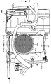
- Fig. 2 is an exploded perspective view showing an example of the air cooling system;
- Fig. 3 is a front view of the air cooler with the PDU and the down converter;
- Fig. 4 is an exploded perspective view showing the positional relationship between the PDU and the air cooler; and
- Fig. 5 is a plan view of a primary part of a hybrid vehicle on which the air-intaking and exhausting apparatus in the air cooling system according to the present invention can preferably be mounted.
-
- The present invention will be described in more detail referring to the accompanying drawings. Fig. 5 is a plan view showing a primary part of a hybrid vehicle to which an air-intaking and exhausting apparatus in an air cooling system according to the present invention is preferably mounted.
- As shown, an
engine 1 mounted in a front section of the hybrid vehicle V comprises a three-cylinderinternal combustion engine 2, amotor generator 3 directly joined to theengine 2 for complementing its output, and atransmission 4. The output of theengine 1 is transmitted by ashaft 5 to a pair offront wheels first battery 8 is provided for supplying an ignition unit of theengine 2 and a lighting unit with an electricity of, for example, rated 12 bolts DC. - Mounted in a rear section of the vehicle V are a
PDU 9 for driving themotor generator 3, a down-converter 10 for transmitting regenerated current generated by themotor generator 3 to thefirst battery 8, and asecond battery 11 provided as a power source for themotor generator 3. Thesecond battery 11 may be of a Ni-MH type with rated 144 volts. The down-converter 10 and thefirst battery 8 are electrically connected to each other by a single-phase cable 12 while themotor generator 3 and thePDU 9 are electrically connected by a three-phase (high-pressure)cable 13. Also, a pair ofrear wheels 14 and 15 is mounted at both, left and right, sides in the rear section of the vehicle V. - In action, a direct current supplied from the
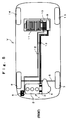
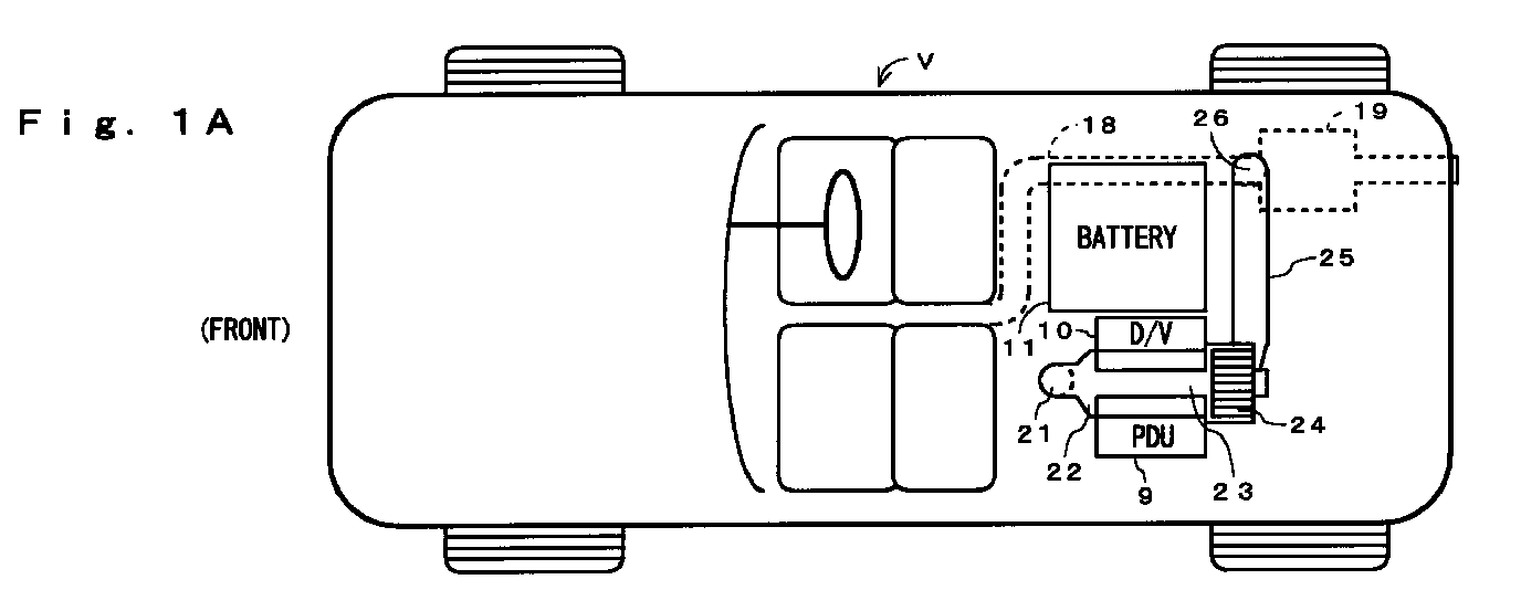
second battery 11 is converted to a three-phase alternate current by an inverter in thePDU 9 and then supplied to themotor generator 3. Themotor generator 3 is joined to a crank shaft of theengine 2 as arranged for, when engergized, driving and complementing the driving force of theengine 2 or, when driven by theengine 2 running in idling mode, generating an electricity which is stored in thefirst battery 8. - Fig. 1A is a schematic plan view of the bottom of a vehicle equipped with the air-intaking and exhausting apparatus in the air-cooling system for the PDU and the down-converter according to the present invention. Fig. 1B is a schematic side view of a primary part of the present invention seen through a side body of the vehicle.
- As shown, a
fuel tank 17, anexhaust pipe 18 connected to theengine 2, and asilencer 19 connected to theexhaust pipe 18 are mounted beneath afloor 16 of the rear section of the vehicle V. Anair inlet 21 for the air cooling system in thefloor 16 is located above thefuel tank 17. Theair inlet 21 is fluidly communicated with anair cooler 23 for the PDU and the down-converter. Thefuel tank 17 has an appropriate shape, e.g. a polyhedron or a convex polyhedron, corresponding to the configuration of thefloor 16 located at the opposite side. The space between a slope 16a of thefloor 16 and thefuel tank 17 is contemplated to have a non-uniform width and a bent. - The
air cooler 23 is linked to afan 24, such as a sirocco fan, which is designed for turning the direction of the flow of incoming air substantially 90 degrees and connected via atube 25 to anexhaust outlet 26 located above thesilencer 19. The air inlet 21 and theexhaust outlet 26 open towards the lower side. As shown, the air cooling system has a right triangle shape comprising a first duct module including theair cooler 23 and atube 22 extending substantially in parallel with the vehicle V and a second duct module including thetube 25 which is bent at substantially a right angle at thefan 24. Theair inlet 21 and theexhaust outlet 26 are provided at two vertices of the right triangle shape respectively. The first and second duct assemblies are placed on substantially a horizontal plane. - An example of the air cooling system will now be explained referring to an exploded perspective view of Fig. 2. The
air inlet 21 may incorporate amaintenance lid 31 of the fuel tank. Themaintenance lid 31 is fixedly mounted by e.g. screws to about the opening of thefloor 16. Aflange 32 is placed on the top of themaintenance lid 31 and joined via amesh screen 33 to atube 34, Theflange 32, thescreen 33, and thetube 34 constitute in a combination atube assembly 35. Thetube 34 is connected by anannular spring 36 to aduct assembly 39 consisting mainly of aduct 37 and aring duct seal 38. - The
duct assembly 39 is connected to aheat sink case 40 in the down converter and the PDU which will be described later. The outlet of theheat sink case 40 is connected by agrommet 41 to afan assembly 42 such as a sirocco fan. The outlet of thefan assembly 42 is turned 90 degrees from the inlet and is further connected by aspring 43 to a tube 44. The tube 44 is connected by anannular spring 45 to aduct 46 and then by anotherannular spring 47 to atube 48. The exit of thetube 48 is fixedly joined to ascreen 49 and aflange 50. Thetube 48, thescreen 49, and theflange 50 constitute a tube assembly 51. Theflange 50 is tightened by e.g. screws to the opening of thefloor 16. - A structure of the
air cooler 23 including theheat sink case 40 with thePDU 9 and thedown converter 10 will be explained referring to Figs. 3 and 4. Fig. 3 is a front view of theair cooler 23 sandwiched between thePDU 9 and thedown converter 10. Fig. 4 is an exploded perspective view showing the positional relationship between thePDU 9 and theheat sink case 40. As shown, a power module PM comprises theair cooler 23 located at the center and thePDU 9 and thedown converter 10 disposed on both sides of theair cooler 23. ThePDU 9 includes a power module body (IPM) 62 consisting of semiconductor switches, a large-size capacitor 64, and a controller 66 for the IPM 62, as shown in Fig. 4. - The
air cooler 23 includes theheat sink case 40, afirst heat sink 401 for thePDU 9, and asecond heat sink 402 for thedown converter 10. Thefirst heat sink 401 comprises wave-like fins brazed to aplate 403 of thePDU 9. Thesecond heat sink 402 comprises wave-like fins brazed to a plate of thedown converter 10. - The two groups of the wave-like fins are arranged with their lengths of pitch equal to each other; particularly, the height H1 of the fins of the
first heat sink 401 is higher than the height H2 of the fins of thesecond heat sink 402. The two heights H1 and H2 are not identical because thePDU 9 and thedown converter 10 are different in the generation of heat. The two groups of the fins are identical in the length of pitch in order to allow the flow of cooling air to be not biased but uniform when running through the fins. - The other components of the
PDU 9 are secured directly or indirectly to theplate 403 of thefirst heat sink 401 while the other components of thedown converter 10 are secured to the plate of thesecond heat sink 402. The two plates of the first 401 and thesecond heat sink 402 are directly joined and tightened to one side of theheat sink case 40 of a box-like shape so that their fins are appropriately positioned in theheat sink case 40. Theplate 403 is tightened by bolts (not shown) to theheat sink case 40 together with aholder 61 of the capacitor. - As best shown in Fig. 3, the
duct assembly 39 is located before theheat sink case 40. The flow of air is introduced from anopening 39A in theduct assembly 39 into thefirst heat sink 401 and thesecond heat sink 402. Theduct assembly 39 hence has thetube 34 provided for intaking the flow of air from the outside of the vehicle V. Thegrommet 41 is connected to the other side of theheat sink case 40 or the opposite side to theduct assembly 39 for discharging the flow of air from theheat sink case 40. - As shown in Fig. 4, the IPM 62 having abase of a radiator sheet (e.g. a copper strip) is seated on a central region of the
plate 403 of thefirst heat sink 401 mounted to one side of theheat sink case 40. The IPM 62 is covered with an IPM case 63 on which thecapacitor 64 supported by theholder 61 is placed. The controller 66 is anchored by a stay 65 onto theholder 61 of thecapacitor 64. - The
air inlet 21 of the air cooling system in the embodiment is located closely above thefuel tank 17, hence hardly permitting any object such as a cobble stone jumping from the road surface to straightforwardly enter theair inlet 21. Accordingly, theair inlet 21 can be prevented from being injured or choked with such an object. In case of running in the snow, adhesion of snow to thescreen 33 of theair inlet 21 can also be avoided. Theair inlet 21 will thus be prevented from being narrowed or blocked with frozen snow. Also, theexhaust outlet 26 is located closely above thesilencer 19 and can hence be prevented from being frozen and reduced in the cross section by the escape of heat from thesilencer 19. - The
floor 16 is commonly made of a highly heat conductive material such as aluminum and when a higher temperature condition e.g. during the summer, can thus be cooled to a lower temperature than the outside by the cooling action in the interior of the vehicle. This allows the flow of air running from a passage between thefloor 16 and thefuel tank 17 to theair inlet 21 to be effectively cooled by the lower temperature of thefloor 16, hence improving the efficiency of action of the air cooler for the PDU and the down converter. - The
fan 24 enables to shift the direction of the flow of air substantially 90 degrees while running from the inlet to the outlet. The shift of the direction of the flow of air through 90 degrees may be carried out by, for example, a sirocco fan without provision of the tubing. This allows the air cooling system of a right triangle shape to be economical and versatile for use in any vehicle. Also, theair inlet 21 and theexhaust outlet 26 are provided at two vertices of the right triangle shape defined by the first duct assembly of thetube 22 and theair cooler 23 and the second duct assembly of thetube 25 bent to substantially a right angle at thefan 24. This permits the space (distance) between theair inlet 21 and theexhaust outlet 26 to be maximized. Accordingly, exhaust gas from theexhaust outlet 26 will hardly be sucked into theair inlet 21 e.g. in the idling mode. The cooling action of theair cooler 23 will thus hardly be offset by a flow of warm air from the heated exhaust gas. As a result, heat generated by the PDU and the down converter during the idling can effectively be dissipated by the cooling action. - The
mesh screen 33 is mounted in theair inlet 21 and enables to filter any object of greater than the mesh size which is thus disallowed to enter theair cooler 23. Themesh screen 33 prevents the fins of the heat sink from being broken and blocked, thus maintaining the cooling effect of the heat sink. - The air cooling system of the present invention is mounted on the
floor 16 of a vehicle while itsair inlet 21 andexhaust output 26 open downwardly of the vehicle or face against the road surface and stay out of sight behind the vehicle body. This contributes to the improvement in the respect of vehicle design. - Although the present invention has been described with reference to preferred embodiments, works skill in the art will recognize that changes may be made in form and detail without departing from the spirit and scope of the invention.
- The present invention provides the following advantages:
- (1) As the distance between the air inlet and the exhaust outlet is maximized, it can prevent a flow of warm air emitted from the exhaust outlet from returning back to the air inlet, thus assisting the cooling action particularly during the idling mode.
- (2) As the air inlet is protected from any object from the the road surface or snow entering directly, its injury or frozen can be avoided.
- (3) As the direction of the flow of air is turned substantially 90 degrees with the use of no tubing, the apparatus can thus be simplified in the construction and reduced in the cost.
- (4) As the exhaust outlet is prevented by heat released from the silencer connected to the exhaust pipe from being frozen, it can contribute to the improvement of the reliability of the apparatus.
- (5) As the air inlet is located in front of the exhaust outlet on the vehicle, the flow of air can efficiently run from the air inlet to the exhaust outlet and effectively be directed by the action of the fan.
-
Claims (8)
- An air-intaking and exhausting apparatus in an air cooling system for a PDU and a down converter comprising:an air inlet (21) provided in the bottom of a vehicle to open downwardly;an air cooler (23) for the PDU (9) and the down converter (10) connected by a first tube (22) to the air inlet (21); andan exhaust outlet (26) provided to open downwardly and connected by a second tube (25) to the air cooler (23), whereinthe first tube and the second tube are placed on a horizontal plane and extended substantially orthogonal to each other.
- An air-intaking and exhausting apparatus in an air cooling system for a PDU and a down converter according to claim 1, wherein at least a portion of the air inlet (21) faces against the top of a fuel tank (17).
- An air-intaking and exhausting apparatus in an air cooling system for a PDU and a down converter according to claim 1 or 2, further comprising a floor (16) consisting mainly of a horizontal portion and a slope portion (16a) which is located at the bottom of the vehicle and wherein the space between the floor (16) and the fuel tank (17) mounted close to the floor is contemplated to have a non-uniform width and a bent for preventing at least an object from the road surface from straightforwardly entering the air inlet (21).
- An air-intaking and exhausting apparatus in an air cooling system for a PDU and a down converter according to claim 1, wherein the air cooler (23) includes a fan (24) for inputting and outputting the flow of air to cool down the PDU (9) and the down converter (10), and the fan (24) is adapted for turning the direction of the flow of air substantially 90 degrees.
- An air-intaking and exhausting apparatus in an air cooling system for a PDU and a down converter according to claim 4, wherein the fan (24) is a sirocco fan.
- An air-intaking and exhausting apparatus in an air cooling system for a PDU and a down converter according to claim 1, wherein the exhaust outlet (26) is located above a silencer (19) connected to the exhaust pipe.
- An air-intaking and exhausting apparatus in an air cooling system for a PDU and a down converter according to claim 1, wherein the air inlet (21) is located in front of the exhaust outlet (26) on the vehicle.
- An air-intaking and exhausting apparatus in an air cooling system for a PDU and a down converter according to claim 1, wherein at least either the air inlet (21) or the exhaust outlet (26) has a mesh screen (33) fitted therein.
Applications Claiming Priority (2)
| Application Number | Priority Date | Filing Date | Title |
|---|---|---|---|
| JP19103799 | 1999-07-05 | ||
| JP19103799A JP3369514B2 (en) | 1999-07-05 | 1999-07-05 | Intake and exhaust system equipment for air cooling system of PDU and downverter |
Publications (3)
| Publication Number | Publication Date |
|---|---|
| EP1067006A2 true EP1067006A2 (en) | 2001-01-10 |
| EP1067006A3 EP1067006A3 (en) | 2003-01-08 |
| EP1067006B1 EP1067006B1 (en) | 2004-04-14 |
Family
ID=16267849
Family Applications (1)
| Application Number | Title | Priority Date | Filing Date |
|---|---|---|---|
| EP00113122A Expired - Lifetime EP1067006B1 (en) | 1999-07-05 | 2000-06-28 | Air-intaking and exhausting apparatus in air cooling systems for power drive unit (pdu) and voltage down-converter |
Country Status (5)
| Country | Link |
|---|---|
| US (1) | US6457542B1 (en) |
| EP (1) | EP1067006B1 (en) |
| JP (1) | JP3369514B2 (en) |
| CA (1) | CA2310797C (en) |
| DE (1) | DE60009800T2 (en) |
Cited By (3)
| Publication number | Priority date | Publication date | Assignee | Title |
|---|---|---|---|---|
| EP1897739A1 (en) * | 2006-09-07 | 2008-03-12 | Honda Motor Co., Ltd | Electrical device cooling structure in vehicle |
| FR2987702A1 (en) * | 2012-03-02 | 2013-09-06 | Peugeot Citroen Automobiles Sa | Ventilation shaft for battery module for traction of e.g. hybrid vehicle, has support for connecting intermediate section to module exit by connections allowing limited displacements of intermediate section with respect to exit of module |
| WO2015149287A1 (en) * | 2014-04-01 | 2015-10-08 | 深圳市智轮电动车驱动技术有限公司 | Temperature control system of electric vehicle |
Families Citing this family (43)
| Publication number | Priority date | Publication date | Assignee | Title |
|---|---|---|---|---|
| JP4421759B2 (en) * | 2000-10-26 | 2010-02-24 | 本田技研工業株式会社 | Cooling structure of automotive power drive unit |
| JP3652634B2 (en) | 2001-10-05 | 2005-05-25 | 本田技研工業株式会社 | Cooling structure for high piezoelectric parts |
| DE10317580B4 (en) * | 2002-04-18 | 2010-09-16 | Hitachi, Ltd. | Electric inverter device with a liquid channel and electric vehicle with such an inverter device |
| US7025159B2 (en) * | 2003-09-12 | 2006-04-11 | Ford Global Technologies, Llc | Cooling system for a vehicle battery |
| JP3784813B2 (en) * | 2003-11-26 | 2006-06-14 | 本田技研工業株式会社 | High-voltage cooling device for vehicle motor and hybrid vehicle |
| JP4285405B2 (en) * | 2004-12-17 | 2009-06-24 | 日産自動車株式会社 | Hybrid car |
| JP4385020B2 (en) * | 2005-06-02 | 2009-12-16 | 本田技研工業株式会社 | Vehicle power supply |
| JP4611820B2 (en) * | 2005-07-04 | 2011-01-12 | 本田技研工業株式会社 | Cooling device for electric unit for vehicle |
| JP4415910B2 (en) | 2005-07-12 | 2010-02-17 | トヨタ自動車株式会社 | Hybrid vehicle structure |
| KR100802767B1 (en) * | 2005-11-04 | 2008-02-12 | 현대자동차주식회사 | Cooling system of battery unit and motor control unit of hybrid vehicle |
| WO2007111659A2 (en) * | 2005-12-08 | 2007-10-04 | Polaris Industries Inc. | Automatic motorcycle |
| JP4812529B2 (en) * | 2006-06-14 | 2011-11-09 | トヨタ自動車株式会社 | Power supply device and vehicle |
| JP4832225B2 (en) * | 2006-09-07 | 2011-12-07 | 本田技研工業株式会社 | Cooling structure for electrical equipment in vehicles |
| US8495890B2 (en) * | 2007-01-22 | 2013-07-30 | Johnson Controls Technology Company | Cooling member |
| US8014110B2 (en) * | 2007-01-22 | 2011-09-06 | Johnson Controls Technology Company | Variable speed drive with integral bypass contactor |
| US8149579B2 (en) * | 2008-03-28 | 2012-04-03 | Johnson Controls Technology Company | Cooling member |
| US20080242211A1 (en) * | 2007-03-30 | 2008-10-02 | Franz Winter | High voltage battery with a pulling ventilator in a fuel cell vehicle |
| CN100585140C (en) * | 2007-07-05 | 2010-01-27 | 力帆实业(集团)股份有限公司 | Gasoline engine windshield and fuel tank assembly |
| KR100992747B1 (en) * | 2007-07-13 | 2010-11-05 | 기아자동차주식회사 | Cooling device for high voltage electric components for hybrid vehicle |
| JP4283326B1 (en) * | 2007-12-25 | 2009-06-24 | 本田技研工業株式会社 | Battery cooling air intake structure |
| US9924631B2 (en) | 2008-04-22 | 2018-03-27 | George E. Alliss | Spool for straight through line feed vegetation trimmer apparatus with modules and spokes |
| US20090309082A1 (en) * | 2008-06-11 | 2009-12-17 | Warn Industries, Inc. | Fan Cooled Winch |
| US7946368B2 (en) * | 2008-07-14 | 2011-05-24 | Deere & Company | Agricultural machine having dedicated multi-section fan unit |
| JP4919102B2 (en) * | 2008-11-17 | 2012-04-18 | 本田技研工業株式会社 | Cooling structure for power supply unit for vehicle |
| JP5360689B2 (en) * | 2009-09-24 | 2013-12-04 | スズキ株式会社 | Vehicle high-voltage cable routing structure |
| JP5024353B2 (en) * | 2009-10-29 | 2012-09-12 | トヨタ自動車株式会社 | Cooling system for electrical equipment |
| US8982586B2 (en) * | 2010-12-23 | 2015-03-17 | Caterpillar Inc. | Method for regulating temperature of transistor-based component |
| US8365858B2 (en) * | 2010-12-27 | 2013-02-05 | Mazda Motor Corporation | Harness arrangement structure of vehicle |
| JP5473954B2 (en) * | 2011-01-14 | 2014-04-16 | 本田技研工業株式会社 | High-voltage equipment device having cooling structure and vehicle equipped with the same |
| US8950533B2 (en) * | 2011-01-31 | 2015-02-10 | GM Global Technology Operations LLC | Cooling arrangement for a component in a vehicle |
| FR2972143B1 (en) * | 2011-03-01 | 2013-09-20 | Renault Sa | SYSTEM FOR CONNECTING A POWER BATTERY TO A MOTOR VEHICLE |
| JP2012183903A (en) | 2011-03-04 | 2012-09-27 | Suzuki Motor Corp | Routing structure of high-voltage cable in vehicle |
| JP5716964B2 (en) * | 2011-09-12 | 2015-05-13 | 株式会社オートネットワーク技術研究所 | Cooling system |
| US8955630B2 (en) * | 2011-12-14 | 2015-02-17 | Honda Motor Co., Ltd. | Symbiotic engine intake system and battery box |
| US8876119B2 (en) * | 2012-09-04 | 2014-11-04 | Caterpillar Inc. | Grommet and seal assembly for cooling pipes passing through sound wall |
| CN104041203B (en) * | 2013-01-08 | 2015-08-05 | 株式会社小松制作所 | Battery-type Work machine and battery-type fork truck |
| US9822752B2 (en) * | 2014-05-19 | 2017-11-21 | Ford Global Technologies, Llc | Vehicle heating system and method |
| USD970321S1 (en) | 2014-11-20 | 2022-11-22 | Torvent Llc | Line trimmer component |
| JP6326007B2 (en) * | 2015-06-12 | 2018-05-16 | 株式会社Subaru | In-vehicle secondary battery cooling system |
| JP2017171176A (en) * | 2016-03-24 | 2017-09-28 | トヨタ自動車株式会社 | Cooling system for on-vehicle battery |
| JP6631565B2 (en) * | 2017-03-08 | 2020-01-15 | トヨタ自動車株式会社 | Vehicle duct structure |
| EP3670223B1 (en) * | 2018-12-21 | 2022-06-29 | Valeo Autosystemy SP. Z.O.O. | A heating ventilation and air conditioning system |
| JP7563885B2 (en) * | 2020-03-04 | 2024-10-08 | 本田技研工業株式会社 | vehicle |
Family Cites Families (14)
| Publication number | Priority date | Publication date | Assignee | Title |
|---|---|---|---|---|
| US4934449A (en) * | 1988-06-15 | 1990-06-19 | J. I. Case Company | Air intake system for an agricultural implement |
| US5082075A (en) * | 1989-09-07 | 1992-01-21 | Globe-Union Inc. | Method and apparatus for thermal control of automotive components |
| US5031712A (en) * | 1989-09-07 | 1991-07-16 | Globe-Union, Inc. | Method and apparatus for thermal control of automotive components |
| JP3125198B2 (en) * | 1991-12-04 | 2001-01-15 | 本田技研工業株式会社 | Battery temperature control device for electric vehicle |
| US5193608A (en) * | 1992-03-25 | 1993-03-16 | Toyo Radiator Co., Ltd. | Radiator with fan for motor vehicles |
| JPH07194139A (en) * | 1993-12-27 | 1995-07-28 | Hitachi Ltd | Electric vehicle inverter cooling device |
| US5427502A (en) * | 1994-03-28 | 1995-06-27 | Deere & Company | Fan shroud aspirator |
| US5588482A (en) * | 1994-09-26 | 1996-12-31 | Ford Motor Company | Ducted cooling system for an automotive vehicle |
| US5542489A (en) * | 1995-05-31 | 1996-08-06 | Ford Motor Company | Battery thermal chamber |
| US6029762A (en) * | 1997-01-22 | 2000-02-29 | Textron Inc. | Battery warmer for extending the range of an electrically powered vehicle |
| DE59808905D1 (en) * | 1998-04-07 | 2003-08-07 | Swatch Group Man Services Ag B | Device for cooling drive units and for heating the interior of a hybrid vehicle |
| US6167976B1 (en) * | 1998-07-30 | 2001-01-02 | Deere & Company | Engine enclosure |
| US6237357B1 (en) * | 1999-06-07 | 2001-05-29 | Mitsubishi Heavy Industries, Ltd. | Vehicular air conditioner using heat pump |
| US6152096A (en) * | 1999-07-06 | 2000-11-28 | Visteon Global Technologies, Inc. | Storage battery protection by engine air intake system |
-
1999
- 1999-07-05 JP JP19103799A patent/JP3369514B2/en not_active Expired - Fee Related
-
2000
- 2000-06-07 CA CA002310797A patent/CA2310797C/en not_active Expired - Fee Related
- 2000-06-28 EP EP00113122A patent/EP1067006B1/en not_active Expired - Lifetime
- 2000-06-28 DE DE60009800T patent/DE60009800T2/en not_active Expired - Fee Related
- 2000-07-03 US US09/609,649 patent/US6457542B1/en not_active Expired - Fee Related
Non-Patent Citations (1)
| Title |
|---|
| None |
Cited By (4)
| Publication number | Priority date | Publication date | Assignee | Title |
|---|---|---|---|---|
| EP1897739A1 (en) * | 2006-09-07 | 2008-03-12 | Honda Motor Co., Ltd | Electrical device cooling structure in vehicle |
| US7688582B2 (en) | 2006-09-07 | 2010-03-30 | Honda Motor Co., Ltd. | Electrical device cooling structure in vehicle |
| FR2987702A1 (en) * | 2012-03-02 | 2013-09-06 | Peugeot Citroen Automobiles Sa | Ventilation shaft for battery module for traction of e.g. hybrid vehicle, has support for connecting intermediate section to module exit by connections allowing limited displacements of intermediate section with respect to exit of module |
| WO2015149287A1 (en) * | 2014-04-01 | 2015-10-08 | 深圳市智轮电动车驱动技术有限公司 | Temperature control system of electric vehicle |
Also Published As
| Publication number | Publication date |
|---|---|
| EP1067006B1 (en) | 2004-04-14 |
| US6457542B1 (en) | 2002-10-01 |
| CA2310797A1 (en) | 2001-01-05 |
| DE60009800D1 (en) | 2004-05-19 |
| DE60009800T2 (en) | 2005-03-31 |
| CA2310797C (en) | 2003-08-05 |
| EP1067006A3 (en) | 2003-01-08 |
| JP2001018664A (en) | 2001-01-23 |
| JP3369514B2 (en) | 2003-01-20 |
Similar Documents
| Publication | Publication Date | Title |
|---|---|---|
| EP1067006B1 (en) | Air-intaking and exhausting apparatus in air cooling systems for power drive unit (pdu) and voltage down-converter | |
| US7049707B2 (en) | Auxiliary power unit for a diesel powered transport vehicle | |
| US7245033B2 (en) | Auxiliary heating and air conditioning unit for a diesel powered transport vehicle | |
| KR100992747B1 (en) | Cooling device for high voltage electric components for hybrid vehicle | |
| US7291932B2 (en) | Auxiliary power unit for a diesel powered transport vehicle | |
| US7079379B2 (en) | Cooling device high voltage electrical unit for motor of vehicle, and hybrid vehicle | |
| EP2180776B1 (en) | Automotive inverter assembly | |
| US6188574B1 (en) | Cooling structure for electric vehicle | |
| US5631821A (en) | Cooling system for electric vehicle inverter system | |
| US7051825B2 (en) | Structure for installing high-voltage equipment component to vehicle | |
| CN1893805A (en) | Cooling apparatus for vehicle electrical packaging unit | |
| US20080310109A1 (en) | Cooling structure for high voltage electrical parts of a hybrid electric vehicle | |
| US20070114083A1 (en) | Vehicle power supply system | |
| JP5182241B2 (en) | Mounting method of cooling unit for electric device for vehicle and cooling unit for electric device for vehicle | |
| CN101666258A (en) | Cooling arrangement for system for generating electric power | |
| CN101346251A (en) | hybrid vehicle | |
| WO2012101795A1 (en) | Cooling apparatus | |
| US8186314B2 (en) | Generator cooling system and method | |
| KR101964354B1 (en) | Automobile | |
| JP4321006B2 (en) | Battery system and cooling structure | |
| JP2005138792A (en) | Hybrid vehicle mounting structure | |
| US20250229653A1 (en) | Stationary inductive charging device | |
| JP4239474B2 (en) | Vehicle drive device | |
| JP2003169403A (en) | Car | |
| EP3626492B1 (en) | Undermount conditioning unit |
Legal Events
| Date | Code | Title | Description |
|---|---|---|---|
| PUAI | Public reference made under article 153(3) epc to a published international application that has entered the european phase |
Free format text: ORIGINAL CODE: 0009012 |
|
| 17P | Request for examination filed |
Effective date: 20000628 |
|
| AK | Designated contracting states |
Kind code of ref document: A2 Designated state(s): AT BE CH CY DE DK ES FI FR GB GR IE IT LI LU MC NL PT SE |
|
| AX | Request for extension of the european patent |
Free format text: AL;LT;LV;MK;RO;SI |
|
| PUAL | Search report despatched |
Free format text: ORIGINAL CODE: 0009013 |
|
| AK | Designated contracting states |
Kind code of ref document: A3 Designated state(s): AT BE CH CY DE DK ES FI FR GB GR IE IT LI LU MC NL PT SE |
|
| AX | Request for extension of the european patent |
Free format text: AL;LT;LV;MK;RO;SI |
|
| AKX | Designation fees paid |
Designated state(s): DE FR GB |
|
| GRAP | Despatch of communication of intention to grant a patent |
Free format text: ORIGINAL CODE: EPIDOSNIGR1 |
|
| RIN1 | Information on inventor provided before grant (corrected) |
Inventor name: HASEGAWA, OSAMU Inventor name: HOSONO, YOSHIO Inventor name: AMAKAI, MASAKI Inventor name: OGAWA, TAICHI Inventor name: TAKEMOTO, HIDEHARU Inventor name: OHTSU, AKIHITO |
|
| GRAS | Grant fee paid |
Free format text: ORIGINAL CODE: EPIDOSNIGR3 |
|
| GRAA | (expected) grant |
Free format text: ORIGINAL CODE: 0009210 |
|
| AK | Designated contracting states |
Kind code of ref document: B1 Designated state(s): DE FR GB |
|
| REG | Reference to a national code |
Ref country code: GB Ref legal event code: FG4D |
|
| REF | Corresponds to: |
Ref document number: 60009800 Country of ref document: DE Date of ref document: 20040519 Kind code of ref document: P |
|
| REG | Reference to a national code |
Ref country code: IE Ref legal event code: FG4D |
|
| ET | Fr: translation filed | ||
| PLBE | No opposition filed within time limit |
Free format text: ORIGINAL CODE: 0009261 |
|
| STAA | Information on the status of an ep patent application or granted ep patent |
Free format text: STATUS: NO OPPOSITION FILED WITHIN TIME LIMIT |
|
| 26N | No opposition filed |
Effective date: 20050117 |
|
| REG | Reference to a national code |
Ref country code: IE Ref legal event code: MM4A |
|
| PGFP | Annual fee paid to national office [announced via postgrant information from national office to epo] |
Ref country code: FR Payment date: 20050608 Year of fee payment: 6 |
|
| PGFP | Annual fee paid to national office [announced via postgrant information from national office to epo] |
Ref country code: GB Payment date: 20060628 Year of fee payment: 7 |
|
| REG | Reference to a national code |
Ref country code: FR Ref legal event code: ST Effective date: 20070228 |
|
| GBPC | Gb: european patent ceased through non-payment of renewal fee |
Effective date: 20070628 |
|
| PG25 | Lapsed in a contracting state [announced via postgrant information from national office to epo] |
Ref country code: FR Free format text: LAPSE BECAUSE OF NON-PAYMENT OF DUE FEES Effective date: 20060630 |
|
| PG25 | Lapsed in a contracting state [announced via postgrant information from national office to epo] |
Ref country code: GB Free format text: LAPSE BECAUSE OF NON-PAYMENT OF DUE FEES Effective date: 20070628 |
|
| PGFP | Annual fee paid to national office [announced via postgrant information from national office to epo] |
Ref country code: DE Payment date: 20080703 Year of fee payment: 9 |
|
| PG25 | Lapsed in a contracting state [announced via postgrant information from national office to epo] |
Ref country code: DE Free format text: LAPSE BECAUSE OF NON-PAYMENT OF DUE FEES Effective date: 20100101 |