EP1066639B1 - Twisted pair cable - Google Patents
Twisted pair cable Download PDFInfo
- Publication number
- EP1066639B1 EP1066639B1 EP99914004A EP99914004A EP1066639B1 EP 1066639 B1 EP1066639 B1 EP 1066639B1 EP 99914004 A EP99914004 A EP 99914004A EP 99914004 A EP99914004 A EP 99914004A EP 1066639 B1 EP1066639 B1 EP 1066639B1
- Authority
- EP
- European Patent Office
- Prior art keywords
- twisted pair
- cable
- impedance
- conductors
- average
- Prior art date
- Legal status (The legal status is an assumption and is not a legal conclusion. Google has not performed a legal analysis and makes no representation as to the accuracy of the status listed.)
- Expired - Lifetime
Links
- 239000004020 conductor Substances 0.000 claims description 69
- 238000002847 impedance measurement Methods 0.000 claims description 19
- 238000005259 measurement Methods 0.000 claims description 14
- 239000003989 dielectric material Substances 0.000 claims description 7
- 238000009413 insulation Methods 0.000 description 17
- 230000005540 biological transmission Effects 0.000 description 6
- 239000000853 adhesive Substances 0.000 description 5
- 230000001070 adhesive effect Effects 0.000 description 5
- 239000000463 material Substances 0.000 description 5
- 229910052751 metal Inorganic materials 0.000 description 5
- 239000002184 metal Substances 0.000 description 5
- 239000007787 solid Substances 0.000 description 4
- 238000005516 engineering process Methods 0.000 description 3
- 239000006260 foam Substances 0.000 description 3
- 239000011248 coating agent Substances 0.000 description 2
- 238000000576 coating method Methods 0.000 description 2
- 230000009977 dual effect Effects 0.000 description 2
- -1 polyethylene Polymers 0.000 description 2
- 238000000926 separation method Methods 0.000 description 2
- RNFJDJUURJAICM-UHFFFAOYSA-N 2,2,4,4,6,6-hexaphenoxy-1,3,5-triaza-2$l^{5},4$l^{5},6$l^{5}-triphosphacyclohexa-1,3,5-triene Chemical compound N=1P(OC=2C=CC=CC=2)(OC=2C=CC=CC=2)=NP(OC=2C=CC=CC=2)(OC=2C=CC=CC=2)=NP=1(OC=1C=CC=CC=1)OC1=CC=CC=C1 RNFJDJUURJAICM-UHFFFAOYSA-N 0.000 description 1
- RYGMFSIKBFXOCR-UHFFFAOYSA-N Copper Chemical compound [Cu] RYGMFSIKBFXOCR-UHFFFAOYSA-N 0.000 description 1
- 229920001780 ECTFE Polymers 0.000 description 1
- 239000004698 Polyethylene Substances 0.000 description 1
- 239000004743 Polypropylene Substances 0.000 description 1
- 229910000831 Steel Inorganic materials 0.000 description 1
- 239000004809 Teflon Substances 0.000 description 1
- 229920006362 Teflon® Polymers 0.000 description 1
- 238000004026 adhesive bonding Methods 0.000 description 1
- 239000000956 alloy Substances 0.000 description 1
- 229910045601 alloy Inorganic materials 0.000 description 1
- 229910052782 aluminium Inorganic materials 0.000 description 1
- XAGFODPZIPBFFR-UHFFFAOYSA-N aluminium Chemical compound [Al] XAGFODPZIPBFFR-UHFFFAOYSA-N 0.000 description 1
- 238000010276 construction Methods 0.000 description 1
- 238000001816 cooling Methods 0.000 description 1
- 229920001577 copolymer Polymers 0.000 description 1
- 239000010949 copper Substances 0.000 description 1
- 229910052802 copper Inorganic materials 0.000 description 1
- 230000008878 coupling Effects 0.000 description 1
- 238000010168 coupling process Methods 0.000 description 1
- 238000005859 coupling reaction Methods 0.000 description 1
- 229920003020 cross-linked polyethylene Polymers 0.000 description 1
- 239000004703 cross-linked polyethylene Substances 0.000 description 1
- 230000008030 elimination Effects 0.000 description 1
- 238000003379 elimination reaction Methods 0.000 description 1
- 239000011152 fibreglass Substances 0.000 description 1
- 239000003063 flame retardant Substances 0.000 description 1
- 239000004811 fluoropolymer Substances 0.000 description 1
- 229920002313 fluoropolymer Polymers 0.000 description 1
- 239000007769 metal material Substances 0.000 description 1
- 229920000573 polyethylene Polymers 0.000 description 1
- 229920001155 polypropylene Polymers 0.000 description 1
- 229920000915 polyvinyl chloride Polymers 0.000 description 1
- 239000004800 polyvinyl chloride Substances 0.000 description 1
- 230000001902 propagating effect Effects 0.000 description 1
- 238000005070 sampling Methods 0.000 description 1
- 229910052709 silver Inorganic materials 0.000 description 1
- 239000004332 silver Substances 0.000 description 1
- 230000000087 stabilizing effect Effects 0.000 description 1
- 239000010959 steel Substances 0.000 description 1
- 239000000758 substrate Substances 0.000 description 1
- 238000004804 winding Methods 0.000 description 1
Images
Classifications
-
- H—ELECTRICITY
- H01—ELECTRIC ELEMENTS
- H01B—CABLES; CONDUCTORS; INSULATORS; SELECTION OF MATERIALS FOR THEIR CONDUCTIVE, INSULATING OR DIELECTRIC PROPERTIES
- H01B11/00—Communication cables or conductors
- H01B11/02—Cables with twisted pairs or quads
-
- H—ELECTRICITY
- H01—ELECTRIC ELEMENTS
- H01B—CABLES; CONDUCTORS; INSULATORS; SELECTION OF MATERIALS FOR THEIR CONDUCTIVE, INSULATING OR DIELECTRIC PROPERTIES
- H01B11/00—Communication cables or conductors
- H01B11/002—Pair constructions
-
- C—CHEMISTRY; METALLURGY
- C08—ORGANIC MACROMOLECULAR COMPOUNDS; THEIR PREPARATION OR CHEMICAL WORKING-UP; COMPOSITIONS BASED THEREON
- C08L—COMPOSITIONS OF MACROMOLECULAR COMPOUNDS
- C08L23/00—Compositions of homopolymers or copolymers of unsaturated aliphatic hydrocarbons having only one carbon-to-carbon double bond; Compositions of derivatives of such polymers
- C08L23/02—Compositions of homopolymers or copolymers of unsaturated aliphatic hydrocarbons having only one carbon-to-carbon double bond; Compositions of derivatives of such polymers not modified by chemical after-treatment
- C08L23/10—Homopolymers or copolymers of propene
-
- H—ELECTRICITY
- H01—ELECTRIC ELEMENTS
- H01B—CABLES; CONDUCTORS; INSULATORS; SELECTION OF MATERIALS FOR THEIR CONDUCTIVE, INSULATING OR DIELECTRIC PROPERTIES
- H01B3/00—Insulators or insulating bodies characterised by the insulating materials; Selection of materials for their insulating or dielectric properties
- H01B3/18—Insulators or insulating bodies characterised by the insulating materials; Selection of materials for their insulating or dielectric properties mainly consisting of organic substances
- H01B3/30—Insulators or insulating bodies characterised by the insulating materials; Selection of materials for their insulating or dielectric properties mainly consisting of organic substances plastics; resins; waxes
- H01B3/44—Insulators or insulating bodies characterised by the insulating materials; Selection of materials for their insulating or dielectric properties mainly consisting of organic substances plastics; resins; waxes vinyl resins; acrylic resins
- H01B3/441—Insulators or insulating bodies characterised by the insulating materials; Selection of materials for their insulating or dielectric properties mainly consisting of organic substances plastics; resins; waxes vinyl resins; acrylic resins from alkenes
-
- H—ELECTRICITY
- H01—ELECTRIC ELEMENTS
- H01B—CABLES; CONDUCTORS; INSULATORS; SELECTION OF MATERIALS FOR THEIR CONDUCTIVE, INSULATING OR DIELECTRIC PROPERTIES
- H01B7/00—Insulated conductors or cables characterised by their form
- H01B7/17—Protection against damage caused by external factors, e.g. sheaths or armouring
- H01B7/29—Protection against damage caused by extremes of temperature or by flame
- H01B7/295—Protection against damage caused by extremes of temperature or by flame using material resistant to flame
-
- C—CHEMISTRY; METALLURGY
- C08—ORGANIC MACROMOLECULAR COMPOUNDS; THEIR PREPARATION OR CHEMICAL WORKING-UP; COMPOSITIONS BASED THEREON
- C08L—COMPOSITIONS OF MACROMOLECULAR COMPOUNDS
- C08L23/00—Compositions of homopolymers or copolymers of unsaturated aliphatic hydrocarbons having only one carbon-to-carbon double bond; Compositions of derivatives of such polymers
- C08L23/02—Compositions of homopolymers or copolymers of unsaturated aliphatic hydrocarbons having only one carbon-to-carbon double bond; Compositions of derivatives of such polymers not modified by chemical after-treatment
- C08L23/04—Homopolymers or copolymers of ethene
- C08L23/08—Copolymers of ethene
- C08L23/0807—Copolymers of ethene with unsaturated hydrocarbons only containing four or more carbon atoms
- C08L23/0815—Copolymers of ethene with unsaturated hydrocarbons only containing four or more carbon atoms with aliphatic 1-olefins containing one carbon-to-carbon double bond
-
- C—CHEMISTRY; METALLURGY
- C08—ORGANIC MACROMOLECULAR COMPOUNDS; THEIR PREPARATION OR CHEMICAL WORKING-UP; COMPOSITIONS BASED THEREON
- C08L—COMPOSITIONS OF MACROMOLECULAR COMPOUNDS
- C08L27/00—Compositions of homopolymers or copolymers of compounds having one or more unsaturated aliphatic radicals, each having only one carbon-to-carbon double bond, and at least one being terminated by a halogen; Compositions of derivatives of such polymers
- C08L27/02—Compositions of homopolymers or copolymers of compounds having one or more unsaturated aliphatic radicals, each having only one carbon-to-carbon double bond, and at least one being terminated by a halogen; Compositions of derivatives of such polymers not modified by chemical after-treatment
- C08L27/12—Compositions of homopolymers or copolymers of compounds having one or more unsaturated aliphatic radicals, each having only one carbon-to-carbon double bond, and at least one being terminated by a halogen; Compositions of derivatives of such polymers not modified by chemical after-treatment containing fluorine atoms
Definitions
- the present invention relates to twisted pair cables which can be used in high frequency applications and more particularly, the present invention relates to high frequency twisted pair cables having a pair of insulated conductors with each insulated conductor having a first foam insulating layer surrounding the conductor and a second insulation layer surrounding the first layer.
- Twisted pair technology advances have primarily focused on near end crosstalk.
- Both U.S. Patent 3,102,160 and U.S. Patent 4,873,393 teach the importance of utilizing pairs which are twisted with lengths of lay different from integral multiples of the lengths of lay of other paired conductors within the cable. This is done to minimize electrical coupling between paired conductors.
- U.S. Patent 5,015,800 focuses on another important issue of maintaining a controlled impedance throughout the transmission line. It teaches how impedance can be stabilized by the elimination of air gaps around a twisted pair embodiment through the use of a dual dielectric which has outer layers bonded after the insulated conductors are twisted.
- a twisted pair cable comprising the features of the preamble of claim 1 is disclosed in US-A-5 606 151 .
- This reference shows a twisted pair cable having two conductors with the dielectrics surrounding each conductor.
- the conductors and corresponding dielectric layers are twisted substantially along the length of said cable to provide the twisted pair cable.
- the first dielectric layer being a foamed dielectric
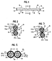
- Figs. 1 and 2 show one embodiment of our twisted pair cable 10 that can be used in high frequency applications.
- the cable 10 has two solid, stranded or hollow conductor wires 12 and 13.
- the conductors are solid metal, a plurality of metal strands, an appropriate fiber glass conductor, a layered metal or combination thereof.
- Each conductor 12 and 13 is surrounded by respective cylindrical dielectric or insulation 14 and 15. Each of the conductors 12 and 13 is disposed centrally within and thus substantially concentric with the corresponding insulations 14 and 15.
- the conductors 12 and 13 may, if desired, adhere to any degree against the inner walls of their respective insulation by any suitable means, such as by bonding, by heat or adhesives to prevent relative rotation between the conductors and insulations.
- the insulation 14 has an inner or first layer of foam dielectric 14a surrounding the conductor 12 and an outer or second layer of dielectric 146 surrounding the first layer 14a.
- the insulation 15 has an inner or first layer of foam dielectric 15a surrounding the conductor 13 and an outer or second layer of dielectric 15b surrounding the first layer 15a.
- the cable 10 has a common insulation for both conductors 12 and 13 as shown in Fig. 2 where the insulations 14a and 15a and the insulations 14b and 15b are integral with each other and are joined together along their lengths in any suitable manner.
- the joining means is an integral web 18 which extends from the diametric axis of each insulation.
- the width 19 of the web is in the range of from about 6.35 x 10 -4 cm (0.00025 in.) to about 0.381cm (0.150 in.).
- the thickness 21 of the web is also in the range of from about 6.35x10 -4 cm (0.00025 in.) to about 0.381cm (0.150 inches).
- the web thickness is preferably less than the thickness 22 of both dielectric layers.
- the web width is preferably less than the thickness 22 of the dielectric layers.
- the diameter (traditionally expressed in AWG size) of each of the conductors 12 and 13 are preferably between about 18 to about 40 AWG.
- the conductors 12 and 13 are preferably metal conductors and may be constructed of any suitable metallic material such as solid or strands of copper, metal coated substrate, silver, aluminum, steel, alloys or a combination thereof.
- the dielectric may be suitable material used in the insulation of cables such as foamed and non-foamed polyvinylchloride, polyethylene, polypropylene or fluoro-copolymers (such as Teflon, which is a registered trademark of DuPont), fluoropolymers (such as HALAR which is a trademark of Ausimont), cross-linked polyethylene, rubber, etc. Many of the insulations may contain a flame retardant.
- first layer of foamed dielectric 14a and 15a are the same material as the second dielectric 14b and 15b which may be a partially foamed or non-foamed material.
- the thickness 22 of the dielectric layers 14 and 15 is in the range of from about 6.35x10 -4 cm (0.00025 in.) to about 0.381cm (0.150 in.).
- the dual conductors surrounded by the joined dielectric(s) layers 14 and 15 are twisted to form a twisted pair cable.
- the variation in the distance between the centers of adjacent conductors, hereinafter referred to as the center-to-center distances, along the twisted pair cable is very small.
- the center-to-center distance d at any one point along the twisted pair cable does not vary by more than ⁇ 0.03 times the average of center-to-center distances measured along the twisted parallel cable with the average being calculated by randomly selecting three 305m (1000 ft). twisted pair cables of the same size from the same run or three successive runs on three separate days, taking 20 measurements on each cable at least 6.1m (20 ft.) apart and calculating the average of all the measurements.
- Fig. 3 illustrates another embodiment of our invention wherein the joining means is a solid integral web 18a which is formed by the second layers 14b and 15b. Since the dimensions are within the ranges set forth above, the same numbering is used.
- Fig. 4 illustrates another embodiment of our invention.
- the twisted pair cable 23 is joined or bonded together substantially along their entire length at 24 by an appropriate adhesive or the adjacent second dielectric layers are bonded together by causing material contact while the dielectrics are at elevated temperatures and then cooling to provide a joined cable having no adhesive.
- the non-adhesive bonding provides an integral common dielectric second layer for the two conductors 25 and 26.
- the conductors 25 and 26 have an AWG size of from about 18 to about 40.
- the thickness of the combined dielectric insulation coating 27a and 27b or 28a and 28b are from about 6.35 x 10 -4 cm (0.00025 in.) to about 0.381cm (0.150 in.).
- the contact between the two dielectrics 27b and 28b being such that the thickness of the contact is preferably less than the thickness of one of the dielectric layers.
- the dielectric layers 27a are foamed dielectrics of the same materials as dielectrics 14a and 15a, the dielectric layers 27b and 28b are the same as the dielectric layers 14b and 15b.
- the bonding at 24 or webs 18 and 18a are such that the dielectric layers can be separated and remain intact with a force of not more than 2.26 kgs (5 lbs).
- Any number of twisted pair cables may be incorporated into an overall jacketed or unjacketed cable with an optional metallic shield under the encasement, or applied over each twisted pair or groups of twisted pairs.
- the cables 10, 10a and 23 provide for relatively error free transmissions within most frequencies utilized by LAN systems.
- the impedance of the cable is controlled by two main factors; conductor spacing and dielectric between the conductors. The more uniform the conductor spacing and dielectric, the more uniform the impedance.
- twisted pair cables 10, 10a and 23 each have center-to-center distances d measured between the centers of adjacent conductors that is ⁇ 0.03 times the average of d with the variation being not any more than this at any point along a 305m (1000 ft). twisted pair cable.
- the following exemplifies 4 twisted pair joined 24 AWG cables that we prepared and measured and that do not have the required center-to-center distance d of the present invention.
- the cables have an average center-to-center conductor spacing of 0.089cm (0.0353 in.). This average d in inches is taken from three randomly selected 305m (1000 ft). lengths of cable taken from three successive runs on three separate days, with 20 measurements taken in at least 6.1m (20 ft.) intervals on each cable. The results are shown in the following table wherein all the measurements are in inches. Sample Cable 1(d) Cable 2 (d) Cable 3 (d).
- One way to measure the amount of structural variation in a cable is by sending a signal along the transmission line (cable path) and measuring the amount of energy reflected back towards the testing apparatus.
- the reflected electrical energy peaks at particular frequencies (often referred to as "spikes" within the cable industry). This is the result of a cylindrical variation in the construction which matches the cyclical wave (or frequency) propagating down the cable. The more energy reflected back, the less energy is available at the other end of the cable.
- the actual reflected energy can be predicted by the impedance stability of the transmission line. If a 100 ohm impedance signal is sent down the cable, any part of the cable which is not exactly 100 ohms will cause a reflection.
- each twisted pair cable have an impedance of from 90 to 110 ohms when measured at high frequencies of about 10MHz to about 200MHz with a tolerance of no greater than ⁇ 5%.
- the tolerance is determined by multiplying ⁇ 0.05 times an average impedance.
- the average impedance is calculated by taking impedance measurements between about 10 MHz to about 200 MHz on random samplings of 305m (1000 ft). twisted pair cables of the same size with at least one impedance measurement on each of at least twenty (20) random samples of 305m (1000 ft). twisted pair cables taken from the same run.
- Another average impedance which would be acceptable would be taking at least one impedance measurement on at least twenty randomly selected 305m (1000 ft). twisted pair cables of the same size taken from three separate successive runs on at least three separate days.
- the 305m (1000 ft). twisted pairs are rated for an impedance of about 90 to about 110 ohms when measured at a frequency of between 10. MHz and 200 MHz.
- the acceptable 305m (1000 ft). twisted pair will have an impedance at any frequency between 10 MHz and 200 MHz that varies no greater than ⁇ 0.05 times the average impedance.
- no impedance measurement between 10 MHz and 200 MHz can be greater than 101.0 ohms (96.2+4.8[96.2x0.05]) or less than 91.4 ohms (96.2-4.8[96.2x0.05]).
- Still another average impedance used in the present invention is calculated by taking at least 200 impedance measurements on one 91.4m- 305m (300-1000 ft.) twisted pair conductor with the at least 200 impedance measurements being taken in less than 0.5 MHz increments. If any of the impedance measurement between 10 and 200 MHz vary by more than or less than 0.05 times the average impedance in the one cable than the cable run is not acceptable.
- the average impedance is calculated in the usual manner i.e. adding all of the impedance measurements and dividing the total by the number of impedance measurements.
- the cables 10, 10a and 23 can each be separated without causing the twist to unravel and separate.
- the adhesion strength is determined by holding one insulated conductor and pulling the other insulated conductor.
- the preferred adhesion strength of between 0.11 (0.25) and 1.13 kgs (2.5 lbs) force for the twisted cables 10, 10a and 23 leaves the insulation 14 and 15 and 27 and 28 substantially intact.
- the twisted pair cables 10, 10a and 23 are prepared by extruding the insulations over two wires simultaneously and then adhering the two insulated conductors via bonding, webbing, or other suitable means.
- the adjoined insulated conductors are twisted to produce the desired number of twists per paired wire cable length.
- the twisted wire cable 23 is preferably prepared by the side-by-side coating of two conductors, first with the foamed dielectric and after the foamed dielectric is appropriately sized, to the desired diameter, the sized foamed dielectric is coated with the second dielectric, then joining the two insulated conductors prior to winding the wires, optionally using an adhesive to bond the two coated wires, and after bonding of the two wires, twisting the joined insulated wires to the desired twist.
Landscapes
- Chemical & Material Sciences (AREA)
- Physics & Mathematics (AREA)
- Spectroscopy & Molecular Physics (AREA)
- Health & Medical Sciences (AREA)
- Chemical Kinetics & Catalysis (AREA)
- Medicinal Chemistry (AREA)
- Polymers & Plastics (AREA)
- Organic Chemistry (AREA)
- Communication Cables (AREA)
Description
- The present invention relates to twisted pair cables which can be used in high frequency applications and more particularly, the present invention relates to high frequency twisted pair cables having a pair of insulated conductors with each insulated conductor having a first foam insulating layer surrounding the conductor and a second insulation layer surrounding the first layer.
- In the past, twisted pair cables were utilized in applications where data speeds reached an upper limit of about 20 kilobits per second. Recent advances in wire technology and hardware equipment have pushed the upper limit of twisted pair cable applications to about several hundred megabits per second.
- Twisted pair technology advances have primarily focused on near end crosstalk. Both
U.S. Patent 3,102,160 andU.S. Patent 4,873,393 teach the importance of utilizing pairs which are twisted with lengths of lay different from integral multiples of the lengths of lay of other paired conductors within the cable. This is done to minimize electrical coupling between paired conductors. -
U.S. Patent 5,015,800 focuses on another important issue of maintaining a controlled impedance throughout the transmission line. It teaches how impedance can be stabilized by the elimination of air gaps around a twisted pair embodiment through the use of a dual dielectric which has outer layers bonded after the insulated conductors are twisted. - When two or more pairs of different average impedance are connected together to form a transmission line (often referred to as a channel), part of the signal will be reflected at the point of attachment(s). Reflections due to impedance mismatch ultimately causes problems with signal loss and tracking errors (jitter).
- Prior attempts to control conductor spacing has been entirely for the purposes of stabilizing capacitance within a cable. It is well known in the industry that utilizing a cable with uniform capacitance between its pairs has the advantage of reducing crosstalk.
U.S. Patent 3,102,160 explains how equal and uniform capacitance can be achieved along a transmission line by simultaneously extruding dielectric over two conductors. - However,
U.S. Patent 3,102,160 did not recognize problems encountered with impedance mismatch at high frequencies. The impedance of the cable was of little importance provided the capacitance of each pair within the cable was relatively uniform. The problem is in that different cables can have uniform capacitances between their respective pairs and yet possess different average impedances. - Another problem with the
U.S. Patent 3,102,160 is with regard to insulated conductor separation. In order for the pairs of the said cable to be used with current LAN systems and connecting hardware, the adjoined insulated conductors must have the ability to be separated from one another for at least 2.5cm (1 inch) along the length of the pair. The prior art provides no means for the separation of the two adjoined insulated conductors. - A twisted pair cable comprising the features of the preamble of claim 1 is disclosed in
US-A-5 606 151 . This reference shows a twisted pair cable having two conductors with the dielectrics surrounding each conductor. - The conductors and corresponding dielectric layers are twisted substantially along the length of said cable to provide the twisted pair cable.
- The features distinguishing the invention over the prior art are given in the characterizing part of claim 1.
- Accordingly, with the first dielectric layer being a foamed dielectric, it is an object of this invention to provide a twisted pair cable having two conductors, at least two dielectric layers surrounding each conductor, the conductors and corresponding dielectric layers being twisted substantially along the length of the cable to provide the twisted pair cable having a center-to-center distance between the two twisted conductors varying over any 305m (1000 ft) length ± 0.03 times an average center-to-center distance with the average center-to-center distance being the average of at least 20 distance measurements taken at least 6.1m (20 ft.) apart from three randomly selected 305m (1000 ft) twisted cable of the same size taken from the same run or from three successive runs.
- It is a further object of this invention to provide a twisted pair cable having two conductors, a dielectric layer surrounding each conductor, the conductors and corresponding dielectric layers being twisted substantially along the length of the cable to provide the twisted pair cable having over any 305m (1000) ft., an impedance of about 90 to 110 ohms when measured at frequencies of about 10 MHz to about 200 MHz, the impedance being within an impedance tolerance of ± 5% of an average impedance, the average impedance being:
- a. an average of at least one impedance measurement on each of at least twenty 305m (1,000 ft.) twisted pair cables of the same size taken from the same run, or
- b. an average of at least one impedance measurement from each of twenty randomly selected 305m (1000 ft). twisted pair cables of the same size, taken from three separate successive runs with each run being at least 24 hours apart from each other, or
- c. selecting one twisted pair cable of from 91.4m-305m (300 to 1000 ft.) and taking at least 200 impedance measurements on the one twisted pair cable with the at least 200 impedance measurements being at between 10 MHz and 200 MHz taken in less than 0.5 MHz. increments.
- The present invention and advantages thereof will become more apparent upon consideration of the following detailed description when taken in conjunction with the accompanying drawings.
-
- Fig. 1 is a side view of a twisted pair cable in accordance with a preferred embodiment of the invention.
- Fig. 2 is an enlarged cross section taken along lines 2-2 of Fig. 1.
- Fig. 3 is a cross-section similar to Fig. 2 of another embodiment of the present invention.
- Fig. 4 is an enlarged cross-sectional view of another embodiment of a twisted pair cable.
- Figs. 1 and 2 show one embodiment of our
twisted pair cable 10 that can be used in high frequency applications. Thecable 10 has two solid, stranded orhollow conductor wires - Each
conductor insulation conductors corresponding insulations conductors insulation 14 has an inner or first layer of foam dielectric 14a surrounding theconductor 12 and an outer or second layer of dielectric 146 surrounding the first layer 14a. Theinsulation 15 has an inner or first layer of foam dielectric 15a surrounding theconductor 13 and an outer or second layer of dielectric 15b surrounding thefirst layer 15a. - The
cable 10 has a common insulation for bothconductors insulations 14a and 15a and theinsulations 14b and 15b are integral with each other and are joined together along their lengths in any suitable manner. As shown, the joining means is anintegral web 18 which extends from the diametric axis of each insulation. Thewidth 19 of the web is in the range of from about 6.35 x 10⁻⁴cm (0.00025 in.) to about 0.381cm (0.150 in.). Thethickness 21 of the web is also in the range of from about 6.35x10⁻⁴cm (0.00025 in.) to about 0.381cm (0.150 inches). The web thickness is preferably less than thethickness 22 of both dielectric layers. The web width is preferably less than thethickness 22 of the dielectric layers. - The diameter (traditionally expressed in AWG size) of each of the
conductors - The
conductors - It is preferred that the first layer of foamed dielectric 14a and 15a are the same material as the second dielectric 14b and 15b which may be a partially foamed or non-foamed material.
- The
thickness 22 of thedielectric layers - The dual conductors surrounded by the joined dielectric(s) layers 14 and 15 are twisted to form a twisted pair cable. The variation in the distance between the centers of adjacent conductors, hereinafter referred to as the center-to-center distances, along the twisted pair cable is very small. The center-to-center distance d at any one point along the twisted pair cable does not vary by more than ± 0.03 times the average of center-to-center distances measured along the twisted parallel cable with the average being calculated by randomly selecting three 305m (1000 ft). twisted pair cables of the same size from the same run or three successive runs on three separate days, taking 20 measurements on each cable at least 6.1m (20 ft.) apart and calculating the average of all the measurements.
- Fig. 3 illustrates another embodiment of our invention wherein the joining means is a solid integral web 18a which is formed by the
second layers 14b and 15b. Since the dimensions are within the ranges set forth above, the same numbering is used. - Fig. 4 illustrates another embodiment of our invention. The
twisted pair cable 23 is joined or bonded together substantially along their entire length at 24 by an appropriate adhesive or the adjacent second dielectric layers are bonded together by causing material contact while the dielectrics are at elevated temperatures and then cooling to provide a joined cable having no adhesive. The non-adhesive bonding provides an integral common dielectric second layer for the twoconductors conductors dielectric insulation coating 27a and 27b or 28a and 28b are from about 6.35 x 10⁻⁴cm (0.00025 in.) to about 0.381cm (0.150 in.). The contact between the two dielectrics 27b and 28b being such that the thickness of the contact is preferably less than the thickness of one of the dielectric layers. Thedielectric layers 27a are foamed dielectrics of the same materials asdielectrics 14a and 15a, the dielectric layers 27b and 28b are the same as thedielectric layers 14b and 15b. - The bonding at 24 or
webs 18 and 18a are such that the dielectric layers can be separated and remain intact with a force of not more than 2.26 kgs (5 lbs). We provide an adhesive strength between the dielectrics of between 0.044 to 2-26 kgs (0.1 to 5 lbs). force and preferably between 0.11 and 1.13 kgs force (0.25 to 2.5 lbs. force). - When being used in patch panels, punch down blocks, and connectors, it becomes necessary for the two insulated conductors to be segregated from each other. The spread can be up to one inch or more. With Twin-Lead type technology, the two conductors cannot be uniformly detached - a distinct disadvantage when compared to our invention. It should also be noted that many connectors, such as the commonly used RJ-45 jack, require that the individual insulated conductors be uniformly round. With our invention, once the singles are detached, they will retain their roundness independent of each other.
- Any number of twisted pair cables may be incorporated into an overall jacketed or unjacketed cable with an optional metallic shield under the encasement, or applied over each twisted pair or groups of twisted pairs.
- The
cables - An important feature of the present invention is that our
twisted pair cables - To measure the average of d in our twisted pair cables, we randomly select at least three and preferably twenty 305m (1000 ft). samples of cable of the same size from the same run or at least three separate successive runs with each of the successive runs occurring on a separate day or 24 hour period. The average d is calculated by taking at least 20 measurements on each 305m (1000 ft). cable with each measurement taken at least 6.1m (20 ft.) apart, adding all the measurements taken and dividing the added measurements by the total number of measurements taken. All of the d measurements taken fall within the tolerances of ± 0.03 times the average d. If they do not, the twisted pair cables from those runs are discarded.
- The following exemplifies 4 twisted pair joined 24 AWG cables that we prepared and measured and that do not have the required center-to-center distance d of the present invention. The cables have an average center-to-center conductor spacing of 0.089cm (0.0353 in.). This average d in inches is taken from three randomly selected 305m (1000 ft). lengths of cable taken from three successive runs on three separate days, with 20 measurements taken in at least 6.1m (20 ft.) intervals on each cable. The results are shown in the following table wherein all the measurements are in inches.
Sample Cable 1(d) Cable 2 (d) Cable 3 (d). cm " cm " cm " 1 .0902 (.0355) .0924 (.0364) .0874 (.0344) 2 .0894 (.0352) .0935 (.0368) .0864 (.0340) 3 .0909 (.0358) .0925 (.0364) .0866 (.0341) 4 .0897 (.0353) .0907 (.0357) .0879 (.0346) 5 .0884 (.0348) .0890 (.0352) .0874 (.0344) 6 .0864 (.0340) .0904 (.0356) .0884 (.0348) 7 .0881 (.0347) .0904 (.0356) .0894 (.0352) 8 .0886 (.0349) .0912 (.0359) .0876 (.0345) 9 .0902 (.0355) .0932 (.0367) .0866 (.0341) 10 .0919 (.0362) .0919 (.0362) .0881 (.0347) 11 .0932 (.0367) .0930 (.0366) .0894 (.0352) 12 .0922 (.0363) .0922 (.0363) .0889 (.0350) 13 .0899 (.0354) .0904 (.0356) .0904 (.0356) 14 .0884 (.0348) .0881 (.0347) .0899 (.0354) 15 .0876 (.0345) .0902 (.0355) .0891 (.0351) 16 .0874 (.0344) .0894 (.0352) .0876 (.0345) 17 .0891 (.0351) .0912 (.0359) .0874 (.0344) 18 .0904 (.0356) .0922 (.0363) .0866 (.0341) 19 .0891 (.0351) .0930 (.0366) .0853 (.0336) 20 .0881 (.0347) .0935 (.0368) .0851 (.0335) TOTAL 1.7894 (.7045) 1.8273 (.7194) 1.7556 (.6912) Cable Totals 1+2+3 divided by 60 .0897 (.0353") - In this case, the range of acceptable d is from 0.0869 to 0.0924cm (0.0342 to 0.0364 in.), i.e., 0.0897cm (0.0353 in.) (the average) ± 0.0027cm (0.0011 in.) = ± 0.03 x 0.0897cm (0.0353 in)). Since in the above example there are measurements outside this tolerance in each of the cables, all of the twisted pair cables from each of these runs would be rejected.
- One way to measure the amount of structural variation in a cable is by sending a signal along the transmission line (cable path) and measuring the amount of energy reflected back towards the testing apparatus. Sometimes the reflected electrical energy peaks at particular frequencies (often referred to as "spikes" within the cable industry). This is the result of a cylindrical variation in the construction which matches the cyclical wave (or frequency) propagating down the cable. The more energy reflected back, the less energy is available at the other end of the cable.
- The actual reflected energy can be predicted by the impedance stability of the transmission line. If a 100 ohm impedance signal is sent down the cable, any part of the cable which is not exactly 100 ohms will cause a reflection.
- Therefore, an alternative and/or combined feature of our
twisted pairs - Another average impedance which would be acceptable would be taking at least one impedance measurement on at least twenty randomly selected 305m (1000 ft). twisted pair cables of the same size taken from three separate successive runs on at least three separate days. The 305m (1000 ft). twisted pairs are rated for an impedance of about 90 to about 110 ohms when measured at a frequency of between 10. MHz and 200 MHz. As noted above, the acceptable 305m (1000 ft). twisted pair will have an impedance at any frequency between 10 MHz and 200 MHz that varies no greater than ±0.05 times the average impedance. For example, if the average impedance is 96.2 ohms, no impedance measurement between 10 MHz and 200 MHz can be greater than 101.0 ohms (96.2+4.8[96.2x0.05]) or less than 91.4 ohms (96.2-4.8[96.2x0.05]).
- Still another average impedance used in the present invention is calculated by taking at least 200 impedance measurements on one 91.4m- 305m (300-1000 ft.) twisted pair conductor with the at least 200 impedance measurements being taken in less than 0.5 MHz increments. If any of the impedance measurement between 10 and 200 MHz vary by more than or less than 0.05 times the average impedance in the one cable than the cable run is not acceptable.
- The average impedance is calculated in the usual manner i.e. adding all of the impedance measurements and dividing the total by the number of impedance measurements.
- The pulling apart of the twisted pair cables for at least 2,54cm (an inch), leaves the
insulation cables - The adhesion strength is determined by holding one insulated conductor and pulling the other insulated conductor. The preferred adhesion strength of between 0.11 (0.25) and 1.13 kgs (2.5 lbs) force for the
twisted cables insulation - The
twisted pair cables - The
twisted wire cable 23 is preferably prepared by the side-by-side coating of two conductors, first with the foamed dielectric and after the foamed dielectric is appropriately sized, to the desired diameter, the sized foamed dielectric is coated with the second dielectric, then joining the two insulated conductors prior to winding the wires, optionally using an adhesive to bond the two coated wires, and after bonding of the two wires, twisting the joined insulated wires to the desired twist. - The foregoing description is for purposes of illustration only and is not intended to limit the scope of protection accorded this invention. The scope of protection is to be measured by the following claims.
Claims (6)
- A twisted pair cable (10) having two conductors (12,13) with dielectrics (14,15) surrounding each conductor (12,13), the conductors (12,13) and corresponding dielectric layers (14,15) being twisted substantially along the length of said cable to provide the twisted pair cable,
characterized by,
a first (14a, 15a) and second dielectric (14b, 15b) layer surrounding each conductor (12,13), the first dielectric layer (14a, 15a) being a foamed dielectric, the second dielectric layer (14b, 15b) surrounding the first dielectric layer (14a, 15a),
the twisted pair cable (10) has over any 305 m(1000 ft.) an impedance of about 90 to 110 ohms when measured at frequencies of about 10 MHz to about 200 MHz, the impedance being within an impedance tolerance of < 5% of an average impedance, the average impedance being:a. an average of at least one impedance measurement on each of at least twenty 305 m(1,000 ft.) twisted pair conductors (12,13) of the same size taken from the same run, orb. an average of at least one impedance measurement from each of twenty randomly selected 305 m(1000 ft). twisted pair conductors (12,13) of the same size, taken from three separate successive runs with each run being at least 24 hours apart from each other, orc. selecting one twisted pair conductor (12,13) of from 91.4m to 305m (300 to 1000 ft.) and taking at least 200 impedance measurements on said one twisted pair conductor (12,13) with said at least 200 impedance measurements being at between 10 MHz and 200 MHz taken in less than 0.5 MHz increments. - The twisted pair cable of claim 1 characterized by
the impedance average is obtained by selecting one twisted pair conductor (12,13) from twenty consecutive 305m (1000 ft). twisted pair conductors (12,13) and taking at least 200 impedance measurements on said one twisted pair conductor (12,13) with said at least 200 impedance measurements being at between 10 MHz and 200 MHz taken in less than 0.5 MHz increments. - The cable of claim 1 or 2 characterized in that the first and second dielectric layers (14,15) of each conductor (12,13) has a combined thickness (22) in the range of about 6.35x10⁻⁴ to 0.381 cm (0.00025 to about 0.150 in.).
- The cable of claim 1, 2 or 3 characterized in that the dielectric layers (14, 15) of each conductor (12,13) are joined together by a webbing (18, 18a) extending from the diametrical axes of the dielectric layers (14,15) and the webbing has a thickness (21) and width (19) that are less than the diameter of the conductors (12,13).
- The cable of any one of claims 1-4 characterized in that each of the conductors (12,13) are fixed within the first dielectric layers (14,15) so that said each of said conductors (12,13) is unable to rotate within the first dielectric layers.
- The cable of any one of claims 1-5 characterized in that the twisted pair cable (10) has a center-to-center distance (d) at any point along the twisted pair cable (10) that does not vary by more than 0.03 times an average center-to-center distance, the average center-to-center distance being an average of at least 20 center-to-center distance measurements on each of at least three randomly selected 305 m(1,000 ft.) twisted pair cables (10) of the same size, each measurement being taken at least 6.1 m (20 feet) apart and taken from the same run or from three separate runs on three successive days.
Applications Claiming Priority (3)
| Application Number | Priority Date | Filing Date | Title |
|---|---|---|---|
| US49635 | 1998-03-27 | ||
| US09/049,635 US6222129B1 (en) | 1993-03-17 | 1998-03-27 | Twisted pair cable |
| PCT/US1999/006127 WO1999050856A1 (en) | 1998-03-27 | 1999-03-26 | Twisted pair cable |
Publications (3)
| Publication Number | Publication Date |
|---|---|
| EP1066639A1 EP1066639A1 (en) | 2001-01-10 |
| EP1066639A4 EP1066639A4 (en) | 2003-04-02 |
| EP1066639B1 true EP1066639B1 (en) | 2007-11-07 |
Family
ID=21960872
Family Applications (1)
| Application Number | Title | Priority Date | Filing Date |
|---|---|---|---|
| EP99914004A Expired - Lifetime EP1066639B1 (en) | 1998-03-27 | 1999-03-26 | Twisted pair cable |
Country Status (11)
| Country | Link |
|---|---|
| US (1) | US6222129B1 (en) |
| EP (1) | EP1066639B1 (en) |
| JP (1) | JP2002510138A (en) |
| KR (1) | KR20010034687A (en) |
| CN (1) | CN1308966C (en) |
| AU (1) | AU748714B2 (en) |
| BR (1) | BRPI9909175B1 (en) |
| CA (1) | CA2324599C (en) |
| DE (1) | DE69937487T2 (en) |
| NZ (1) | NZ506977A (en) |
| WO (1) | WO1999050856A1 (en) |
Families Citing this family (48)
| Publication number | Priority date | Publication date | Assignee | Title |
|---|---|---|---|---|
| US6441308B1 (en) * | 1996-06-07 | 2002-08-27 | Cable Design Technologies, Inc. | Cable with dual layer jacket |
| US6074503A (en) | 1997-04-22 | 2000-06-13 | Cable Design Technologies, Inc. | Making enhanced data cable with cross-twist cabled core profile |
| US7405360B2 (en) | 1997-04-22 | 2008-07-29 | Belden Technologies, Inc. | Data cable with cross-twist cabled core profile |
| US7154043B2 (en) * | 1997-04-22 | 2006-12-26 | Belden Technologies, Inc. | Data cable with cross-twist cabled core profile |
| WO2003094178A1 (en) * | 2002-05-02 | 2003-11-13 | Belden Technologies, Inc. | Surfaced cable filler |
| US7049523B2 (en) * | 2002-08-30 | 2006-05-23 | Belden Technologies, Inc. | Separable multi-member composite cable |
| KR100496452B1 (en) * | 2002-11-18 | 2005-06-20 | 엘에스전선 주식회사 | Hybrid cable for communication |
| CN103124189A (en) | 2003-07-11 | 2013-05-29 | 泛达公司 | Alien crosstalk suppression with enhanced patch cord |
| US7115815B2 (en) * | 2003-10-31 | 2006-10-03 | Adc Telecommunications, Inc. | Cable utilizing varying lay length mechanisms to minimize alien crosstalk |
| US7214884B2 (en) * | 2003-10-31 | 2007-05-08 | Adc Incorporated | Cable with offset filler |
| WO2006014889A1 (en) * | 2004-07-27 | 2006-02-09 | Belden Cdt Networking, Inc. | Dual-insulated, fixed together pair of conductors |
| US7064277B1 (en) | 2004-12-16 | 2006-06-20 | General Cable Technology Corporation | Reduced alien crosstalk electrical cable |
| US7238885B2 (en) * | 2004-12-16 | 2007-07-03 | Panduit Corp. | Reduced alien crosstalk electrical cable with filler element |
| US7157644B2 (en) | 2004-12-16 | 2007-01-02 | General Cable Technology Corporation | Reduced alien crosstalk electrical cable with filler element |
| US7317163B2 (en) * | 2004-12-16 | 2008-01-08 | General Cable Technology Corp. | Reduced alien crosstalk electrical cable with filler element |
| US20060160402A1 (en) * | 2004-12-29 | 2006-07-20 | Kowalski Wayne J | Power limited circuit cable for plenum applications in a constant current lighting system |
| EP1911044B1 (en) * | 2005-07-29 | 2012-07-18 | Prysmian Cables Et Systemes France | Substantially flat fire-resistant safety cable |
| CN101371319A (en) * | 2005-12-09 | 2009-02-18 | 贝尔登技术公司 | Twisted pair cable with improved crosstalk isolation |
| US7375284B2 (en) * | 2006-06-21 | 2008-05-20 | Adc Telecommunications, Inc. | Multi-pair cable with varying lay length |
| CN100535668C (en) * | 2006-07-13 | 2009-09-02 | 旺矽科技股份有限公司 | High-frequency probe card |
| US7696437B2 (en) * | 2006-09-21 | 2010-04-13 | Belden Technologies, Inc. | Telecommunications cable |
| US7473848B2 (en) | 2007-04-25 | 2009-01-06 | E.I. Dupont De Nemours And Company | Crust resistant twisted pair communications cable |
| US20080303604A1 (en) * | 2007-06-07 | 2008-12-11 | Vincent Ao | Transmission cable capable of controlling and regulating its characteristic impedance and electromagnetic interference simultaneously |
| CN101458979B (en) * | 2007-12-13 | 2012-06-27 | 华为技术有限公司 | Communication electric cable, system, cabinet and twisted pair matching method in communication electric cable |
| US20100078196A1 (en) * | 2007-12-19 | 2010-04-01 | Mclaughlin Thomas | Category cable using dissimilar solid multiple layer |
| US7795539B2 (en) * | 2008-03-17 | 2010-09-14 | E. I. Du Pont De Nemours And Company | Crush resistant conductor insulation |
| US7897873B2 (en) * | 2009-02-12 | 2011-03-01 | Commscope Inc. Of North Carolina | Communications cables having outer surface with reduced coefficient of friction and methods of making same |
| CN102055051B (en) * | 2009-10-30 | 2015-09-30 | 清华大学 | A kind of high-impedance transmission line |
| US8889990B2 (en) * | 2009-11-18 | 2014-11-18 | General Cable Technologies Corporation | Varied wire insulation using both foamed and unfoamed sections |
| US9396846B2 (en) * | 2009-11-18 | 2016-07-19 | General Cable Technologies Corporation | Method of post-twinning dual solid foamed insulation |
| CN102157227A (en) * | 2010-11-29 | 2011-08-17 | 韦玉林 | Bonding type network twisted pair and production method and production equipment thereof |
| CN102157228A (en) * | 2010-11-29 | 2011-08-17 | 韦玉林 | Binding type network twisted pair as well as method and device for manufacturing same |
| EP2584567B1 (en) * | 2011-10-20 | 2016-02-10 | Nexans | Easily stripped electric cable |
| US8855653B2 (en) | 2012-07-18 | 2014-10-07 | Alcatel Lucent | Method, apparatus and computer readable medium for traffic redistribution in wireless networks |
| US11336058B2 (en) * | 2013-03-14 | 2022-05-17 | Aptiv Technologies Limited | Shielded cable assembly |
| DE102014201992A1 (en) * | 2014-02-04 | 2015-08-06 | Leoni Bordnetz-Systeme Gmbh | Electric cable and method for producing an electrical cable bundle |
| CN106847390B (en) * | 2016-08-31 | 2018-05-15 | 凡甲电子(苏州)有限公司 | Data transmission cable |
| DE102015216470A1 (en) * | 2015-08-28 | 2017-03-02 | Leoni Kabel Holding Gmbh | Cables, in particular data transmission cables, wires and methods for producing such a wire |
| CN205984340U (en) * | 2016-01-22 | 2017-02-22 | 3M创新有限公司 | Flat electric cable and cable subassembly |
| US10170220B2 (en) | 2016-01-27 | 2019-01-01 | Hitachi Cable America, Inc. | Extended frequency range balanced twisted pair transmission line or communication cable |
| JP6075490B1 (en) | 2016-03-31 | 2017-02-08 | 株式会社オートネットワーク技術研究所 | Shield wire for communication |
| DE112016006665T5 (en) * | 2016-03-31 | 2018-12-20 | Autonetworks Technologies, Ltd. | communication cable |
| WO2018040958A1 (en) * | 2016-08-31 | 2018-03-08 | 凡甲电子(苏州)有限公司 | Data transmission cable |
| DE112018000634T5 (en) * | 2017-02-01 | 2019-11-14 | Autonetworks Technologies, Ltd. | communication cable |
| CN107358998A (en) * | 2017-07-20 | 2017-11-17 | 杭州乐荣电线电器有限公司 | Flat anti-interference foldable soft data line |
| CN107316705A (en) * | 2017-07-20 | 2017-11-03 | 杭州乐荣电线电器有限公司 | One kind can be to flap-like data wire |
| US10522272B2 (en) * | 2018-02-08 | 2019-12-31 | Delphi Technologies, Llc | Method of manufacturing a twisted pair wire cable and a twisted pair wire cable formed by said method |
| WO2021257342A1 (en) * | 2020-06-20 | 2021-12-23 | Daikin Industries, Ltd. | System and method for forming wire and cable |
Family Cites Families (30)
| Publication number | Priority date | Publication date | Assignee | Title |
|---|---|---|---|---|
| FR1265877A (en) | 1960-05-23 | 1961-07-07 | Telecommunications Sa | Improvements to symmetrical pairs and quads for telephone cables and their manufacturing process |
| US3102160A (en) | 1961-12-22 | 1963-08-27 | Whitney Blake Co | Telephone cable construction |
| DE1665739A1 (en) * | 1963-09-25 | 1971-03-18 | Siemens Ag | Method of insulating thin electrical conductors |
| US3219752A (en) * | 1965-02-17 | 1965-11-23 | Columbia Wire And Supply Compa | High frequency electrical lead-in cable |
| US3361871A (en) * | 1965-08-19 | 1968-01-02 | Whitney Blake Co | Telephone cable construction |
| US3715458A (en) | 1971-11-01 | 1973-02-06 | Belden Corp | Electrical cable structure |
| DE2213693C2 (en) | 1972-03-17 | 1973-12-06 | Siemens Ag, 1000 Berlin U. 8000 Muenchen | Method for producing a stranding group of an electrical cable made up of SZ verseiltex stranding units |
| US3761842A (en) | 1972-06-01 | 1973-09-25 | Bell Telephone Labor Inc | Twisted pair flat conductor cable with means to equalize impedance and propagation velocity |
| US4010231A (en) | 1974-05-22 | 1977-03-01 | Nalco Chemical Company | Method of sealing leaks in metal oil storage containers |
| US4356345A (en) | 1980-10-31 | 1982-10-26 | General Electric Company | Multiconductor cable assembly |
| DE3169897D1 (en) | 1980-12-19 | 1985-05-15 | Kupferdraht Isolierwerk Ag | Overhead cable with tension members |
| US4467138A (en) | 1983-01-17 | 1984-08-21 | Gk Technologies, Inc. | Plural conductor communication wire |
| US4486619A (en) | 1983-05-12 | 1984-12-04 | Minnesota Mining And Manufacturing Company | Uniform twisted wire pair electrical ribbon cable |
| US4873393A (en) | 1988-03-21 | 1989-10-10 | American Telephone And Telegraph Company, At&T Bell Laboratories | Local area network cabling arrangement |
| US4933513A (en) | 1989-05-08 | 1990-06-12 | Noel Lee | Electrical signal conductor assembly |
| US5015800A (en) | 1989-12-20 | 1991-05-14 | Supercomputer Systems Limited Partnership | Miniature controlled-impedance transmission line cable and method of manufacture |
| US5010210A (en) | 1990-06-21 | 1991-04-23 | Northern Telecom Limited | Telecommunications cable |
| US5245134A (en) | 1990-08-29 | 1993-09-14 | W. L. Gore & Associates, Inc. | Polytetrafluoroethylene multiconductor cable and process for manufacture thereof |
| US5103067A (en) | 1991-02-19 | 1992-04-07 | Champlain Cable Corporation | Shielded wire and cable |
| US5142100A (en) | 1991-05-01 | 1992-08-25 | Supercomputer Systems Limited Partnership | Transmission line with fluid-permeable jacket |
| US5162609A (en) | 1991-07-31 | 1992-11-10 | At&T Bell Laboratories | Fire-resistant cable for transmitting high frequency signals |
| CA2090053C (en) | 1992-03-24 | 1997-10-28 | Lawrence Russell Dunn | Hybrid communications cable for enhancement of transmission capability |
| US5270486A (en) * | 1992-05-29 | 1993-12-14 | At&T Bell Laboratories | Metallic transmission medium disposed in stabilized plastic insulation |
| US5283390A (en) | 1992-07-07 | 1994-02-01 | W. L. Gore & Associates, Inc. | Twisted pair data bus cable |
| US5342991A (en) | 1993-03-03 | 1994-08-30 | The Whitaker Corporation | Flexible hybrid branch cable |
| US5606151A (en) * | 1993-03-17 | 1997-02-25 | Belden Wire & Cable Company | Twisted parallel cable |
| US5744757A (en) * | 1995-03-28 | 1998-04-28 | Belden Wire & Cable Company | Plenum cable |
| JPH0850820A (en) * | 1994-08-09 | 1996-02-20 | Hitachi Cable Ltd | Unshielded balanced pair type cable for high speed digital signal transmission |
| US5670748A (en) * | 1995-02-15 | 1997-09-23 | Alphagary Corporation | Flame retardant and smoke suppressant composite electrical insulation, insulated electrical conductors and jacketed plenum cable formed therefrom |
| US5770820A (en) * | 1995-03-15 | 1998-06-23 | Belden Wire & Cable Co | Plenum cable |
-
1998
- 1998-03-27 US US09/049,635 patent/US6222129B1/en not_active Expired - Lifetime
-
1999
- 1999-03-26 DE DE69937487T patent/DE69937487T2/en not_active Expired - Lifetime
- 1999-03-26 EP EP99914004A patent/EP1066639B1/en not_active Expired - Lifetime
- 1999-03-26 AU AU31952/99A patent/AU748714B2/en not_active Ceased
- 1999-03-26 CA CA002324599A patent/CA2324599C/en not_active Expired - Lifetime
- 1999-03-26 KR KR1020007010658A patent/KR20010034687A/en not_active Ceased
- 1999-03-26 CN CNB998044571A patent/CN1308966C/en not_active Expired - Lifetime
- 1999-03-26 JP JP2000541692A patent/JP2002510138A/en active Pending
- 1999-03-26 WO PCT/US1999/006127 patent/WO1999050856A1/en not_active Ceased
- 1999-03-26 NZ NZ506977A patent/NZ506977A/en not_active IP Right Cessation
- 1999-03-26 BR BRPI9909175A patent/BRPI9909175B1/en not_active IP Right Cessation
Also Published As
| Publication number | Publication date |
|---|---|
| EP1066639A4 (en) | 2003-04-02 |
| BRPI9909175B1 (en) | 2016-04-19 |
| US6222129B1 (en) | 2001-04-24 |
| AU748714B2 (en) | 2002-06-13 |
| CN1308966C (en) | 2007-04-04 |
| DE69937487T2 (en) | 2008-02-21 |
| NZ506977A (en) | 2003-05-30 |
| BR9909175A (en) | 2000-12-05 |
| KR20010034687A (en) | 2001-04-25 |
| AU3195299A (en) | 1999-10-18 |
| EP1066639A1 (en) | 2001-01-10 |
| HK1033995A1 (en) | 2001-10-05 |
| WO1999050856A1 (en) | 1999-10-07 |
| CA2324599C (en) | 2003-07-08 |
| JP2002510138A (en) | 2002-04-02 |
| DE69937487D1 (en) | 2007-12-20 |
| CN1295713A (en) | 2001-05-16 |
| CA2324599A1 (en) | 1999-10-07 |
Similar Documents
| Publication | Publication Date | Title |
|---|---|---|
| AU748714B2 (en) | Twisted pair cable | |
| US5734126A (en) | Twisted pair cable | |
| US5393929A (en) | Electrical insulation and articles thereof | |
| US5744757A (en) | Plenum cable | |
| EP1395997B1 (en) | Communications cable provided with a crosstalk barrier for use at high transmission frequencies | |
| KR100708407B1 (en) | Low delay skew multi-pair cable and method of manufacturing the same | |
| AU2002308441A1 (en) | Communications cable provided with a crosstalk barrier for use at high transmission frequencies | |
| US6333465B1 (en) | Data transmission cable | |
| US6476329B2 (en) | Twisted flat cable | |
| NZ522175A (en) | Twisted pair cable | |
| GB2311407A (en) | High frequency cable | |
| MXPA00009352A (en) | Twisted pair cable | |
| JPH1196837A (en) | communication cable | |
| HK1017481A (en) | High frequency cable | |
| HK1033995B (en) | Twisted pair cable |
Legal Events
| Date | Code | Title | Description |
|---|---|---|---|
| PUAI | Public reference made under article 153(3) epc to a published international application that has entered the european phase |
Free format text: ORIGINAL CODE: 0009012 |
|
| 17P | Request for examination filed |
Effective date: 20000921 |
|
| AK | Designated contracting states |
Kind code of ref document: A1 Designated state(s): CH DE ES FR GB IE IT LI NL |
|
| A4 | Supplementary search report drawn up and despatched |
Effective date: 20030219 |
|
| 17Q | First examination report despatched |
Effective date: 20060306 |
|
| GRAP | Despatch of communication of intention to grant a patent |
Free format text: ORIGINAL CODE: EPIDOSNIGR1 |
|
| GRAS | Grant fee paid |
Free format text: ORIGINAL CODE: EPIDOSNIGR3 |
|
| GRAA | (expected) grant |
Free format text: ORIGINAL CODE: 0009210 |
|
| AK | Designated contracting states |
Kind code of ref document: B1 Designated state(s): CH DE ES FR GB IE IT LI NL |
|
| REG | Reference to a national code |
Ref country code: GB Ref legal event code: FG4D |
|
| REG | Reference to a national code |
Ref country code: IE Ref legal event code: FG4D |
|
| REG | Reference to a national code |
Ref country code: CH Ref legal event code: EP |
|
| REF | Corresponds to: |
Ref document number: 69937487 Country of ref document: DE Date of ref document: 20071220 Kind code of ref document: P |
|
| PG25 | Lapsed in a contracting state [announced via postgrant information from national office to epo] |
Ref country code: NL Free format text: LAPSE BECAUSE OF FAILURE TO SUBMIT A TRANSLATION OF THE DESCRIPTION OR TO PAY THE FEE WITHIN THE PRESCRIBED TIME-LIMIT Effective date: 20071107 Ref country code: LI Free format text: LAPSE BECAUSE OF FAILURE TO SUBMIT A TRANSLATION OF THE DESCRIPTION OR TO PAY THE FEE WITHIN THE PRESCRIBED TIME-LIMIT Effective date: 20071107 Ref country code: ES Free format text: LAPSE BECAUSE OF FAILURE TO SUBMIT A TRANSLATION OF THE DESCRIPTION OR TO PAY THE FEE WITHIN THE PRESCRIBED TIME-LIMIT Effective date: 20080218 Ref country code: CH Free format text: LAPSE BECAUSE OF FAILURE TO SUBMIT A TRANSLATION OF THE DESCRIPTION OR TO PAY THE FEE WITHIN THE PRESCRIBED TIME-LIMIT Effective date: 20071107 |
|
| NLV1 | Nl: lapsed or annulled due to failure to fulfill the requirements of art. 29p and 29m of the patents act | ||
| REG | Reference to a national code |
Ref country code: CH Ref legal event code: PL |
|
| EN | Fr: translation not filed | ||
| PLBE | No opposition filed within time limit |
Free format text: ORIGINAL CODE: 0009261 |
|
| STAA | Information on the status of an ep patent application or granted ep patent |
Free format text: STATUS: NO OPPOSITION FILED WITHIN TIME LIMIT |
|
| 26N | No opposition filed |
Effective date: 20080808 |
|
| PG25 | Lapsed in a contracting state [announced via postgrant information from national office to epo] |
Ref country code: FR Free format text: LAPSE BECAUSE OF FAILURE TO SUBMIT A TRANSLATION OF THE DESCRIPTION OR TO PAY THE FEE WITHIN THE PRESCRIBED TIME-LIMIT Effective date: 20080822 |
|
| PG25 | Lapsed in a contracting state [announced via postgrant information from national office to epo] |
Ref country code: IE Free format text: LAPSE BECAUSE OF NON-PAYMENT OF DUE FEES Effective date: 20080326 |
|
| PGFP | Annual fee paid to national office [announced via postgrant information from national office to epo] |
Ref country code: DE Payment date: 20120328 Year of fee payment: 14 |
|
| PGFP | Annual fee paid to national office [announced via postgrant information from national office to epo] |
Ref country code: IT Payment date: 20120424 Year of fee payment: 14 |
|
| REG | Reference to a national code |
Ref country code: DE Ref legal event code: R119 Ref document number: 69937487 Country of ref document: DE Effective date: 20131001 |
|
| PG25 | Lapsed in a contracting state [announced via postgrant information from national office to epo] |
Ref country code: DE Free format text: LAPSE BECAUSE OF NON-PAYMENT OF DUE FEES Effective date: 20131001 |
|
| PG25 | Lapsed in a contracting state [announced via postgrant information from national office to epo] |
Ref country code: IT Free format text: LAPSE BECAUSE OF NON-PAYMENT OF DUE FEES Effective date: 20140326 |
|
| PGFP | Annual fee paid to national office [announced via postgrant information from national office to epo] |
Ref country code: GB Payment date: 20150327 Year of fee payment: 17 |
|
| GBPC | Gb: european patent ceased through non-payment of renewal fee |
Effective date: 20160326 |
|
| PG25 | Lapsed in a contracting state [announced via postgrant information from national office to epo] |
Ref country code: GB Free format text: LAPSE BECAUSE OF NON-PAYMENT OF DUE FEES Effective date: 20160326 |