EP1066452B1 - Producing power from liquefied natural gas - Google Patents
Producing power from liquefied natural gas Download PDFInfo
- Publication number
- EP1066452B1 EP1066452B1 EP99914008A EP99914008A EP1066452B1 EP 1066452 B1 EP1066452 B1 EP 1066452B1 EP 99914008 A EP99914008 A EP 99914008A EP 99914008 A EP99914008 A EP 99914008A EP 1066452 B1 EP1066452 B1 EP 1066452B1
- Authority
- EP
- European Patent Office
- Prior art keywords
- heat
- natural gas
- liquefied natural
- heat exchanger
- pressure
- Prior art date
- Legal status (The legal status is an assumption and is not a legal conclusion. Google has not performed a legal analysis and makes no representation as to the accuracy of the status listed.)
- Expired - Lifetime
Links
- 239000003949 liquefied natural gas Substances 0.000 title claims description 43
- 238000000034 method Methods 0.000 claims description 22
- VNWKTOKETHGBQD-UHFFFAOYSA-N methane Chemical compound C VNWKTOKETHGBQD-UHFFFAOYSA-N 0.000 claims description 14
- 239000007789 gas Substances 0.000 claims description 9
- 239000003507 refrigerant Substances 0.000 claims description 8
- 239000000203 mixture Substances 0.000 claims description 6
- XLYOFNOQVPJJNP-UHFFFAOYSA-N water Substances O XLYOFNOQVPJJNP-UHFFFAOYSA-N 0.000 claims description 6
- 239000012530 fluid Substances 0.000 claims description 5
- 239000003345 natural gas Substances 0.000 claims description 5
- 239000013535 sea water Substances 0.000 claims description 4
- 238000005086 pumping Methods 0.000 claims description 3
- OTMSDBZUPAUEDD-UHFFFAOYSA-N Ethane Chemical compound CC OTMSDBZUPAUEDD-UHFFFAOYSA-N 0.000 claims description 2
- 125000004432 carbon atom Chemical group C* 0.000 claims description 2
- 230000005611 electricity Effects 0.000 claims description 2
- 239000003673 groundwater Substances 0.000 claims description 2
- 229930195733 hydrocarbon Natural products 0.000 claims description 2
- 150000002430 hydrocarbons Chemical class 0.000 claims description 2
- 239000002699 waste material Substances 0.000 claims description 2
- 239000003570 air Substances 0.000 claims 1
- 238000010792 warming Methods 0.000 claims 1
- ATUOYWHBWRKTHZ-UHFFFAOYSA-N Propane Chemical compound CCC ATUOYWHBWRKTHZ-UHFFFAOYSA-N 0.000 description 14
- 239000007788 liquid Substances 0.000 description 8
- 239000001294 propane Substances 0.000 description 7
- 238000003860 storage Methods 0.000 description 7
- 230000008901 benefit Effects 0.000 description 3
- 239000006227 byproduct Substances 0.000 description 3
- 238000007710 freezing Methods 0.000 description 3
- 230000008014 freezing Effects 0.000 description 3
- 230000008016 vaporization Effects 0.000 description 3
- 239000012080 ambient air Substances 0.000 description 2
- 238000009835 boiling Methods 0.000 description 2
- 150000001875 compounds Chemical class 0.000 description 2
- 238000012986 modification Methods 0.000 description 2
- 230000004048 modification Effects 0.000 description 2
- 238000009834 vaporization Methods 0.000 description 2
- UGFAIRIUMAVXCW-UHFFFAOYSA-N Carbon monoxide Chemical compound [O+]#[C-] UGFAIRIUMAVXCW-UHFFFAOYSA-N 0.000 description 1
- 241000183024 Populus tremula Species 0.000 description 1
- 230000006835 compression Effects 0.000 description 1
- 238000007906 compression Methods 0.000 description 1
- 238000010586 diagram Methods 0.000 description 1
- 238000009826 distribution Methods 0.000 description 1
- MEKDPHXPVMKCON-UHFFFAOYSA-N ethane;methane Chemical compound C.CC MEKDPHXPVMKCON-UHFFFAOYSA-N 0.000 description 1
- 239000003546 flue gas Substances 0.000 description 1
- 239000000446 fuel Substances 0.000 description 1
- 238000002309 gasification Methods 0.000 description 1
- 238000009434 installation Methods 0.000 description 1
- 238000004519 manufacturing process Methods 0.000 description 1
- 238000010248 power generation Methods 0.000 description 1
- 239000000047 product Substances 0.000 description 1
- 238000004088 simulation Methods 0.000 description 1
- 239000007787 solid Substances 0.000 description 1
Images
Classifications
-
- F—MECHANICAL ENGINEERING; LIGHTING; HEATING; WEAPONS; BLASTING
- F17—STORING OR DISTRIBUTING GASES OR LIQUIDS
- F17C—VESSELS FOR CONTAINING OR STORING COMPRESSED, LIQUEFIED OR SOLIDIFIED GASES; FIXED-CAPACITY GAS-HOLDERS; FILLING VESSELS WITH, OR DISCHARGING FROM VESSELS, COMPRESSED, LIQUEFIED, OR SOLIDIFIED GASES
- F17C9/00—Methods or apparatus for discharging liquefied or solidified gases from vessels not under pressure
- F17C9/02—Methods or apparatus for discharging liquefied or solidified gases from vessels not under pressure with change of state, e.g. vaporisation
-
- F—MECHANICAL ENGINEERING; LIGHTING; HEATING; WEAPONS; BLASTING
- F01—MACHINES OR ENGINES IN GENERAL; ENGINE PLANTS IN GENERAL; STEAM ENGINES
- F01K—STEAM ENGINE PLANTS; STEAM ACCUMULATORS; ENGINE PLANTS NOT OTHERWISE PROVIDED FOR; ENGINES USING SPECIAL WORKING FLUIDS OR CYCLES
- F01K13/00—General layout or general methods of operation of complete plants
-
- F—MECHANICAL ENGINEERING; LIGHTING; HEATING; WEAPONS; BLASTING
- F01—MACHINES OR ENGINES IN GENERAL; ENGINE PLANTS IN GENERAL; STEAM ENGINES
- F01K—STEAM ENGINE PLANTS; STEAM ACCUMULATORS; ENGINE PLANTS NOT OTHERWISE PROVIDED FOR; ENGINES USING SPECIAL WORKING FLUIDS OR CYCLES
- F01K25/00—Plants or engines characterised by use of special working fluids, not otherwise provided for; Plants operating in closed cycles and not otherwise provided for
- F01K25/08—Plants or engines characterised by use of special working fluids, not otherwise provided for; Plants operating in closed cycles and not otherwise provided for using special vapours
- F01K25/10—Plants or engines characterised by use of special working fluids, not otherwise provided for; Plants operating in closed cycles and not otherwise provided for using special vapours the vapours being cold, e.g. ammonia, carbon dioxide, ether
-
- F—MECHANICAL ENGINEERING; LIGHTING; HEATING; WEAPONS; BLASTING
- F17—STORING OR DISTRIBUTING GASES OR LIQUIDS
- F17C—VESSELS FOR CONTAINING OR STORING COMPRESSED, LIQUEFIED OR SOLIDIFIED GASES; FIXED-CAPACITY GAS-HOLDERS; FILLING VESSELS WITH, OR DISCHARGING FROM VESSELS, COMPRESSED, LIQUEFIED, OR SOLIDIFIED GASES
- F17C9/00—Methods or apparatus for discharging liquefied or solidified gases from vessels not under pressure
-
- F—MECHANICAL ENGINEERING; LIGHTING; HEATING; WEAPONS; BLASTING
- F17—STORING OR DISTRIBUTING GASES OR LIQUIDS
- F17C—VESSELS FOR CONTAINING OR STORING COMPRESSED, LIQUEFIED OR SOLIDIFIED GASES; FIXED-CAPACITY GAS-HOLDERS; FILLING VESSELS WITH, OR DISCHARGING FROM VESSELS, COMPRESSED, LIQUEFIED, OR SOLIDIFIED GASES
- F17C2221/00—Handled fluid, in particular type of fluid
- F17C2221/03—Mixtures
- F17C2221/032—Hydrocarbons
- F17C2221/033—Methane, e.g. natural gas, CNG, LNG, GNL, GNC, PLNG
-
- F—MECHANICAL ENGINEERING; LIGHTING; HEATING; WEAPONS; BLASTING
- F17—STORING OR DISTRIBUTING GASES OR LIQUIDS
- F17C—VESSELS FOR CONTAINING OR STORING COMPRESSED, LIQUEFIED OR SOLIDIFIED GASES; FIXED-CAPACITY GAS-HOLDERS; FILLING VESSELS WITH, OR DISCHARGING FROM VESSELS, COMPRESSED, LIQUEFIED, OR SOLIDIFIED GASES
- F17C2223/00—Handled fluid before transfer, i.e. state of fluid when stored in the vessel or before transfer from the vessel
- F17C2223/01—Handled fluid before transfer, i.e. state of fluid when stored in the vessel or before transfer from the vessel characterised by the phase
- F17C2223/0146—Two-phase
- F17C2223/0153—Liquefied gas, e.g. LPG, GPL
- F17C2223/0161—Liquefied gas, e.g. LPG, GPL cryogenic, e.g. LNG, GNL, PLNG
-
- F—MECHANICAL ENGINEERING; LIGHTING; HEATING; WEAPONS; BLASTING
- F17—STORING OR DISTRIBUTING GASES OR LIQUIDS
- F17C—VESSELS FOR CONTAINING OR STORING COMPRESSED, LIQUEFIED OR SOLIDIFIED GASES; FIXED-CAPACITY GAS-HOLDERS; FILLING VESSELS WITH, OR DISCHARGING FROM VESSELS, COMPRESSED, LIQUEFIED, OR SOLIDIFIED GASES
- F17C2223/00—Handled fluid before transfer, i.e. state of fluid when stored in the vessel or before transfer from the vessel
- F17C2223/03—Handled fluid before transfer, i.e. state of fluid when stored in the vessel or before transfer from the vessel characterised by the pressure level
- F17C2223/033—Small pressure, e.g. for liquefied gas
-
- F—MECHANICAL ENGINEERING; LIGHTING; HEATING; WEAPONS; BLASTING
- F17—STORING OR DISTRIBUTING GASES OR LIQUIDS
- F17C—VESSELS FOR CONTAINING OR STORING COMPRESSED, LIQUEFIED OR SOLIDIFIED GASES; FIXED-CAPACITY GAS-HOLDERS; FILLING VESSELS WITH, OR DISCHARGING FROM VESSELS, COMPRESSED, LIQUEFIED, OR SOLIDIFIED GASES
- F17C2225/00—Handled fluid after transfer, i.e. state of fluid after transfer from the vessel
- F17C2225/01—Handled fluid after transfer, i.e. state of fluid after transfer from the vessel characterised by the phase
- F17C2225/0146—Two-phase
- F17C2225/0153—Liquefied gas, e.g. LPG, GPL
- F17C2225/0161—Liquefied gas, e.g. LPG, GPL cryogenic, e.g. LNG, GNL, PLNG
-
- F—MECHANICAL ENGINEERING; LIGHTING; HEATING; WEAPONS; BLASTING
- F17—STORING OR DISTRIBUTING GASES OR LIQUIDS
- F17C—VESSELS FOR CONTAINING OR STORING COMPRESSED, LIQUEFIED OR SOLIDIFIED GASES; FIXED-CAPACITY GAS-HOLDERS; FILLING VESSELS WITH, OR DISCHARGING FROM VESSELS, COMPRESSED, LIQUEFIED, OR SOLIDIFIED GASES
- F17C2225/00—Handled fluid after transfer, i.e. state of fluid after transfer from the vessel
- F17C2225/03—Handled fluid after transfer, i.e. state of fluid after transfer from the vessel characterised by the pressure level
- F17C2225/035—High pressure, i.e. between 10 and 80 bars
-
- F—MECHANICAL ENGINEERING; LIGHTING; HEATING; WEAPONS; BLASTING
- F17—STORING OR DISTRIBUTING GASES OR LIQUIDS
- F17C—VESSELS FOR CONTAINING OR STORING COMPRESSED, LIQUEFIED OR SOLIDIFIED GASES; FIXED-CAPACITY GAS-HOLDERS; FILLING VESSELS WITH, OR DISCHARGING FROM VESSELS, COMPRESSED, LIQUEFIED, OR SOLIDIFIED GASES
- F17C2227/00—Transfer of fluids, i.e. method or means for transferring the fluid; Heat exchange with the fluid
- F17C2227/01—Propulsion of the fluid
- F17C2227/0128—Propulsion of the fluid with pumps or compressors
- F17C2227/0135—Pumps
-
- F—MECHANICAL ENGINEERING; LIGHTING; HEATING; WEAPONS; BLASTING
- F17—STORING OR DISTRIBUTING GASES OR LIQUIDS
- F17C—VESSELS FOR CONTAINING OR STORING COMPRESSED, LIQUEFIED OR SOLIDIFIED GASES; FIXED-CAPACITY GAS-HOLDERS; FILLING VESSELS WITH, OR DISCHARGING FROM VESSELS, COMPRESSED, LIQUEFIED, OR SOLIDIFIED GASES
- F17C2227/00—Transfer of fluids, i.e. method or means for transferring the fluid; Heat exchange with the fluid
- F17C2227/03—Heat exchange with the fluid
- F17C2227/0302—Heat exchange with the fluid by heating
- F17C2227/0309—Heat exchange with the fluid by heating using another fluid
-
- F—MECHANICAL ENGINEERING; LIGHTING; HEATING; WEAPONS; BLASTING
- F17—STORING OR DISTRIBUTING GASES OR LIQUIDS
- F17C—VESSELS FOR CONTAINING OR STORING COMPRESSED, LIQUEFIED OR SOLIDIFIED GASES; FIXED-CAPACITY GAS-HOLDERS; FILLING VESSELS WITH, OR DISCHARGING FROM VESSELS, COMPRESSED, LIQUEFIED, OR SOLIDIFIED GASES
- F17C2227/00—Transfer of fluids, i.e. method or means for transferring the fluid; Heat exchange with the fluid
- F17C2227/03—Heat exchange with the fluid
- F17C2227/0302—Heat exchange with the fluid by heating
- F17C2227/0309—Heat exchange with the fluid by heating using another fluid
- F17C2227/0311—Air heating
-
- F—MECHANICAL ENGINEERING; LIGHTING; HEATING; WEAPONS; BLASTING
- F17—STORING OR DISTRIBUTING GASES OR LIQUIDS
- F17C—VESSELS FOR CONTAINING OR STORING COMPRESSED, LIQUEFIED OR SOLIDIFIED GASES; FIXED-CAPACITY GAS-HOLDERS; FILLING VESSELS WITH, OR DISCHARGING FROM VESSELS, COMPRESSED, LIQUEFIED, OR SOLIDIFIED GASES
- F17C2227/00—Transfer of fluids, i.e. method or means for transferring the fluid; Heat exchange with the fluid
- F17C2227/03—Heat exchange with the fluid
- F17C2227/0302—Heat exchange with the fluid by heating
- F17C2227/0309—Heat exchange with the fluid by heating using another fluid
- F17C2227/0316—Water heating
- F17C2227/0318—Water heating using seawater
-
- F—MECHANICAL ENGINEERING; LIGHTING; HEATING; WEAPONS; BLASTING
- F17—STORING OR DISTRIBUTING GASES OR LIQUIDS
- F17C—VESSELS FOR CONTAINING OR STORING COMPRESSED, LIQUEFIED OR SOLIDIFIED GASES; FIXED-CAPACITY GAS-HOLDERS; FILLING VESSELS WITH, OR DISCHARGING FROM VESSELS, COMPRESSED, LIQUEFIED, OR SOLIDIFIED GASES
- F17C2227/00—Transfer of fluids, i.e. method or means for transferring the fluid; Heat exchange with the fluid
- F17C2227/03—Heat exchange with the fluid
- F17C2227/0302—Heat exchange with the fluid by heating
- F17C2227/0309—Heat exchange with the fluid by heating using another fluid
- F17C2227/0323—Heat exchange with the fluid by heating using another fluid in a closed loop
-
- F—MECHANICAL ENGINEERING; LIGHTING; HEATING; WEAPONS; BLASTING
- F17—STORING OR DISTRIBUTING GASES OR LIQUIDS
- F17C—VESSELS FOR CONTAINING OR STORING COMPRESSED, LIQUEFIED OR SOLIDIFIED GASES; FIXED-CAPACITY GAS-HOLDERS; FILLING VESSELS WITH, OR DISCHARGING FROM VESSELS, COMPRESSED, LIQUEFIED, OR SOLIDIFIED GASES
- F17C2265/00—Effects achieved by gas storage or gas handling
- F17C2265/03—Treating the boil-off
- F17C2265/032—Treating the boil-off by recovery
- F17C2265/037—Treating the boil-off by recovery with pressurising
-
- F—MECHANICAL ENGINEERING; LIGHTING; HEATING; WEAPONS; BLASTING
- F17—STORING OR DISTRIBUTING GASES OR LIQUIDS
- F17C—VESSELS FOR CONTAINING OR STORING COMPRESSED, LIQUEFIED OR SOLIDIFIED GASES; FIXED-CAPACITY GAS-HOLDERS; FILLING VESSELS WITH, OR DISCHARGING FROM VESSELS, COMPRESSED, LIQUEFIED, OR SOLIDIFIED GASES
- F17C2265/00—Effects achieved by gas storage or gas handling
- F17C2265/07—Generating electrical power as side effect
-
- F—MECHANICAL ENGINEERING; LIGHTING; HEATING; WEAPONS; BLASTING
- F17—STORING OR DISTRIBUTING GASES OR LIQUIDS
- F17C—VESSELS FOR CONTAINING OR STORING COMPRESSED, LIQUEFIED OR SOLIDIFIED GASES; FIXED-CAPACITY GAS-HOLDERS; FILLING VESSELS WITH, OR DISCHARGING FROM VESSELS, COMPRESSED, LIQUEFIED, OR SOLIDIFIED GASES
- F17C2270/00—Applications
- F17C2270/01—Applications for fluid transport or storage
- F17C2270/0102—Applications for fluid transport or storage on or in the water
- F17C2270/0105—Ships
-
- F—MECHANICAL ENGINEERING; LIGHTING; HEATING; WEAPONS; BLASTING
- F17—STORING OR DISTRIBUTING GASES OR LIQUIDS
- F17C—VESSELS FOR CONTAINING OR STORING COMPRESSED, LIQUEFIED OR SOLIDIFIED GASES; FIXED-CAPACITY GAS-HOLDERS; FILLING VESSELS WITH, OR DISCHARGING FROM VESSELS, COMPRESSED, LIQUEFIED, OR SOLIDIFIED GASES
- F17C2270/00—Applications
- F17C2270/01—Applications for fluid transport or storage
- F17C2270/0134—Applications for fluid transport or storage placed above the ground
- F17C2270/0136—Terminals
-
- F—MECHANICAL ENGINEERING; LIGHTING; HEATING; WEAPONS; BLASTING
- F17—STORING OR DISTRIBUTING GASES OR LIQUIDS
- F17C—VESSELS FOR CONTAINING OR STORING COMPRESSED, LIQUEFIED OR SOLIDIFIED GASES; FIXED-CAPACITY GAS-HOLDERS; FILLING VESSELS WITH, OR DISCHARGING FROM VESSELS, COMPRESSED, LIQUEFIED, OR SOLIDIFIED GASES
- F17C2270/00—Applications
- F17C2270/05—Applications for industrial use
- F17C2270/0581—Power plants
Definitions
- This invention relates generally to a process for converting liquefied natural gas at one pressure to liquefied natural gas at a higher pressure and producing by-product power by economic use of the available liquefied natural gas cold sink.
- Natural gas is often available in areas remote to where it will be ultimately used. Quite often the source of this fuel is separated from the point of use by a large body of water and it may then prove necessary to transport the natural gas by large vessels designed for such transport. Natural gas is normally transported overseas as cold liquid in carrier vessels. At the receiving terminal, this cold liquid, which in conventional practice is at near atmospheric pressure and at a temperature of about -160°C (-256°F) must be regasified and fed to a distribution system at ambient temperature and at a suitable elevated pressure, generally around 80 atmospheres. This requires the addition of a substantial amount of heat and a process for handling LNG vapors produced during the unloading process. These vapors are sometimes referred to as boil-off gases.
- the LNG liquid is vaporized by liquefying propane, the liquid propane is then vaporized by seawater, and the vaporized propane is used to power a turbine which drives an electric power generator.
- the vaporized propane discharged from the turbine then warms the LNG, causing the LNG to vaporize and the propane to liquefy.
- the principle of power generation from LNG cold potential is based on the Rankine cycle, which is similar to the principle of the conventional thermal power plants.
- U.S. Patent No. 3,183,666 discloses a method of gasifying a liquid gas while producing mechanical energy.
- a liquefied gas to be gasified is pressurized and passed in two separate cycles through two heat exchangers to warm the fluid, thereby producing a pressurized vapor.
- a heat transfer medium is circulated as a working fluid in a closed cycle, and the heat transfer medium is passed through an expansion turbine which in turn produces mechanical energy.
- liquefied natural gas is pumped from a pressure at or near atmospheric pressure to a pressure above 1379 kPa (200 psia).
- the pressurized liquefied natural gas is then passed through a first heat exchanger whereby the pressurized liquefied natural gas is heated to a temperature above -112°C (-170°F) while keeping the liquefied natural gas at or below its bubble point.
- the process of this invention simultaneously produces energy by circulating in a closed power cycle through the first and second heat exchanger a first heat-exchange medium, comprising the steps of (1) passing to the first heat exchanger the first heat-exchange medium in heat exchange with the liquefied gas to at least partially liquefy the first heat-exchange medium; (2) pressurizing the at least partially liquefied first heat-exchange medium by pumping; (3) passing the pressurized first heat-exchange medium of step (2) through the first heat exchange means to at least partially vaporize the liquefied first heat-exchange medium; (4) passing the first heat-exchange medium of step (3) to the second heat exchanger to further heat the first heat-exchange medium to produce a pressurized vapor; (4) passing the vaporized first heat-exchange medium of step (3) through an expansion device to expand the first heat-exchange medium vapor to a lower pressure whereby energy is produced; (5) passing the expanded first heat-exchange medium of step (4) to the first heat exchanger; and (6) repeating steps (1) through
- This process of this invention uses the cold of liquefied natural gas at or near atmospheric pressure to produce a liquefied natural gas product and to provide a power cycle that preferably provides power, part of which is preferably used for the process.
- reference character 10 designates a line for feeding liquefied natural gas (LNG) at or near atmospheric pressure and at a temperature of about -160°C (-256°F) to an insulated storage vessel 11.
- the storage vessel 11 can be an onshore stationary storage vessel or it can be a container on a ship.
- Line 10 may be a line used to load storage vessels on a ship or it can be a line extending from a container on the ship to an onshore storage vessel.
- the major portion of the LNG in vessel 11 is fed through line 12 to a suitable pump 13.
- the pump 13 increases the pressure of the PLNG to the pressure above about 1,380 kPa (200 psia), and preferably above about 2,400 kPa (350 psia).
- the liquefied natural gas discharged from the pump 13 is directed by line 14 through heat exchanger 15 to heat the LNG to a temperature above about -112°C (-170°F).
- the pressurized liquefied natural gas (PLNG) is then directed by line 16 to a suitable transportation or handling system.
- a heat-transfer medium or refrigerant is circulated in a closed-loop cycle.
- the heat-transfer medium is passed from the first heat exchanger 15 by line 17 to a pump 18 in which the pressure of the heat-transfer medium is raised to an elevated pressure.
- the pressure of the cycle medium depends on the desired cycle properties and the type of medium used.
- From pump 18 the heat-transfer medium, which is in liquid condition and at elevated pressure, is passed through line 19 to heat exchanger 15 wherein the heat-transfer medium is heated.
- the heat-transfer medium is passed by line 20 to heat exchanger 26 wherein the heat-transfer medium is further heated.
- Heat from any suitable heat source is introduced to heat exchanger 26 by line 21 and the cooled heat source medium exits the heat exchanger through line 22.
- Any conventional low cost source of heat can be used; for example, ambient air, ground water, seawater, river water, or waste hot water or steam.
- the heat from the heat source passing through the heat exchanger 26 is transferred to the heat-transfer medium.
- This heat-transfer causes the gasification of the heat-transfer medium, so it leaves the heat exchanger 26 as a gas of elevated pressure.
- This gas is passed through line 23 to a suitable work-producing device 24.
- Device 24 is a turbine, which operates by expansion of the vaporized heat-transfer medium.
- the heat-transfer medium is reduced in pressure by passage through the work-producing device 24 and the resulting energy may be recovered in any desired form, such as rotation of a turbine which can be used to drive electrical generators or to drive pumps (such as pumps 13 and 18) used in the regasification process.
- the reduced pressure heat-transfer medium is directed from the work-producing device 24 through line 25 to the first heat exchanger 15 wherein the heat-transfer medium is at least partially condensed, and preferably entirely condensed, and the LNG is heated by a transfer of heat from the heat-transfer medium to the LNG.
- the condensed heat-transfer medium is discharged from the heat exchanger 15 through line 17 to the pump 18, whereby the pressure of the condensed heat-transfer medium is substantially increased.
- the heat-transfer medium may be any fluid having a freezing point below the boiling temperature of the pressurized liquefied natural gas, does not form solids in heat exchangers 15 and 26, and which in passage through heat exchangers 15 and 26 has a temperature above the freezing temperature of the heat source but below the actual temperature of the heat source.
- the heat-transfer medium may therefore be in liquid form during its circulation through heat exchangers 15 and 26 to provide a transfer of sensible heat alternately to and from the heat-transfer medium. It is preferred, however, that the heat-transfer medium be used which goes through at least partial phase changes during circulation through heat exchangers 15 and 26, with a resulting transfer of latent heat.
- the preferred heat-transfer medium has a moderate vapor pressure at a temperature between the actual temperature of the heat source and the freezing temperature of the heat source to provide a vaporization of the heat-transfer medium during passage through heat exchangers 15 and 26.
- the heat-transfer medium in order to have a phase change, must be liquefiable at a temperature above the boiling temperature of the pressurized liquefied natural gas, such that the heat-transfer medium will be condensed during passage through heat exchanger 15.
- the heat-transfer medium can be a pure compound or a mixture of compounds of such composition that the heat-transfer medium will condense over a range of temperatures above the vaporizing temperature range of the liquefied natural gas.
- heat-transfer mediums hydrocarbons having 1 to 6 carbon atoms per molecule such as propane, ethane, and methane, and mixtures thereof, are preferred heat-transfer mediums, particularly since they are normally present in at least minor amounts in natural gas and therefore are readily available.
Landscapes
- Engineering & Computer Science (AREA)
- Mechanical Engineering (AREA)
- General Engineering & Computer Science (AREA)
- Chemical & Material Sciences (AREA)
- Combustion & Propulsion (AREA)
- Filling Or Discharging Of Gas Storage Vessels (AREA)
- Separation By Low-Temperature Treatments (AREA)
- Engine Equipment That Uses Special Cycles (AREA)
Description
- This invention relates generally to a process for converting liquefied natural gas at one pressure to liquefied natural gas at a higher pressure and producing by-product power by economic use of the available liquefied natural gas cold sink.
- Natural gas is often available in areas remote to where it will be ultimately used. Quite often the source of this fuel is separated from the point of use by a large body of water and it may then prove necessary to transport the natural gas by large vessels designed for such transport. Natural gas is normally transported overseas as cold liquid in carrier vessels. At the receiving terminal, this cold liquid, which in conventional practice is at near atmospheric pressure and at a temperature of about -160°C (-256°F) must be regasified and fed to a distribution system at ambient temperature and at a suitable elevated pressure, generally around 80 atmospheres. This requires the addition of a substantial amount of heat and a process for handling LNG vapors produced during the unloading process. These vapors are sometimes referred to as boil-off gases.
- Many suggestions have also been made and some installations have been built to use the large cold potential of the LNG. Some of these processes use the LNG vaporization process to produce by-product power as a way of using the available LNG cold. The available cold is used by using as a hot sink energy sources such as seawater, ambient air, low-pressure steam and flue gas. The heat-transfer between the sinks is effected by using a single component or multi-component heat-transfer medium as the heat exchange media. For example, U.S. Pat. No. 4,320,303 uses propane as a heat-transfer medium in a closed loop process to generate electricity. The LNG liquid is vaporized by liquefying propane, the liquid propane is then vaporized by seawater, and the vaporized propane is used to power a turbine which drives an electric power generator. The vaporized propane discharged from the turbine then warms the LNG, causing the LNG to vaporize and the propane to liquefy. The principle of power generation from LNG cold potential is based on the Rankine cycle, which is similar to the principle of the conventional thermal power plants.
- Before the practice of this invention, all proposals for using the cold potential of LNG involved regasification of the LNG. The prior art did not recognize the benefits of converting liquefied natural gas at one pressure to liquefied natural gas at a higher temperature and using the cold potential of the lower pressure LNG.
- U.S. Patent No. 3,183,666 discloses a method of gasifying a liquid gas while producing mechanical energy. A liquefied gas to be gasified is pressurized and passed in two separate cycles through two heat exchangers to warm the fluid, thereby producing a pressurized vapor. A heat transfer medium is circulated as a working fluid in a closed cycle, and the heat transfer medium is passed through an expansion turbine which in turn produces mechanical energy.
- The subject matter of the invention is defined in claim 1 below. The practice of this invention provides a source of power to meet the compression horsepower needed to convert conventional LNG to pressurized LNG.
- In the process of this invention, liquefied natural gas is pumped from a pressure at or near atmospheric pressure to a pressure above 1379 kPa (200 psia). The pressurized liquefied natural gas is then passed through a first heat exchanger whereby the pressurized liquefied natural gas is heated to a temperature above -112°C (-170°F) while keeping the liquefied natural gas at or below its bubble point. The process of this invention simultaneously produces energy by circulating in a closed power cycle through the first and second heat exchanger a first heat-exchange medium, comprising the steps of (1) passing to the first heat exchanger the first heat-exchange medium in heat exchange with the liquefied gas to at least partially liquefy the first heat-exchange medium; (2) pressurizing the at least partially liquefied first heat-exchange medium by pumping; (3) passing the pressurized first heat-exchange medium of step (2) through the first heat exchange means to at least partially vaporize the liquefied first heat-exchange medium; (4) passing the first heat-exchange medium of step (3) to the second heat exchanger to further heat the first heat-exchange medium to produce a pressurized vapor; (4) passing the vaporized first heat-exchange medium of step (3) through an expansion device to expand the first heat-exchange medium vapor to a lower pressure whereby energy is produced; (5) passing the expanded first heat-exchange medium of step (4) to the first heat exchanger; and (6) repeating steps (1) through (5).
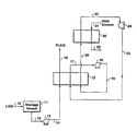
- The present invention and its advantages will be better understood by referring to the following detailed description and the attached drawing which is a schematic flow diagram of one embodiment of this invention to convert LNG at one temperature and pressure to a higher temperature and pressure and recovering power as a by-product. The drawing is not intended to exclude from the scope of the invention other embodiments set out herein or which are the result of normal and expected modifications of the embodiment disclosed in the drawing.
- This process of this invention uses the cold of liquefied natural gas at or near atmospheric pressure to produce a liquefied natural gas product and to provide a power cycle that preferably provides power, part of which is preferably used for the process.
- Referring to the drawing,
reference character 10 designates a line for feeding liquefied natural gas (LNG) at or near atmospheric pressure and at a temperature of about -160°C (-256°F) to aninsulated storage vessel 11. Thestorage vessel 11 can be an onshore stationary storage vessel or it can be a container on a ship.Line 10 may be a line used to load storage vessels on a ship or it can be a line extending from a container on the ship to an onshore storage vessel. - Although a portion of the LNG in
vessel 11 will boil off as a vapor during storage and during unloading of storage containers, the major portion of the LNG invessel 11 is fed throughline 12 to asuitable pump 13. Thepump 13 increases the pressure of the PLNG to the pressure above about 1,380 kPa (200 psia), and preferably above about 2,400 kPa (350 psia). - The liquefied natural gas discharged from the
pump 13 is directed byline 14 through heat exchanger 15 to heat the LNG to a temperature above about -112°C (-170°F). The pressurized liquefied natural gas (PLNG) is then directed byline 16 to a suitable transportation or handling system. - A heat-transfer medium or refrigerant is circulated in a closed-loop cycle. The heat-transfer medium is passed from the first heat exchanger 15 by
line 17 to apump 18 in which the pressure of the heat-transfer medium is raised to an elevated pressure. The pressure of the cycle medium depends on the desired cycle properties and the type of medium used. Frompump 18 the heat-transfer medium, which is in liquid condition and at elevated pressure, is passed throughline 19 to heat exchanger 15 wherein the heat-transfer medium is heated. From the heat exchanger 15, the heat-transfer medium is passed byline 20 to heat exchanger 26 wherein the heat-transfer medium is further heated. - Heat from any suitable heat source is introduced to heat exchanger 26 by
line 21 and the cooled heat source medium exits the heat exchanger throughline 22. Any conventional low cost source of heat can be used; for example, ambient air, ground water, seawater, river water, or waste hot water or steam. The heat from the heat source passing through the heat exchanger 26 is transferred to the heat-transfer medium. This heat-transfer causes the gasification of the heat-transfer medium, so it leaves the heat exchanger 26 as a gas of elevated pressure. This gas is passed throughline 23 to a suitable work-producingdevice 24.Device 24 is a turbine, which operates by expansion of the vaporized heat-transfer medium. The heat-transfer medium is reduced in pressure by passage through the work-producingdevice 24 and the resulting energy may be recovered in any desired form, such as rotation of a turbine which can be used to drive electrical generators or to drive pumps (such aspumps 13 and 18) used in the regasification process. - The reduced pressure heat-transfer medium is directed from the work-producing
device 24 throughline 25 to the first heat exchanger 15 wherein the heat-transfer medium is at least partially condensed, and preferably entirely condensed, and the LNG is heated by a transfer of heat from the heat-transfer medium to the LNG. The condensed heat-transfer medium is discharged from the heat exchanger 15 throughline 17 to thepump 18, whereby the pressure of the condensed heat-transfer medium is substantially increased. - The heat-transfer medium may be any fluid having a freezing point below the boiling temperature of the pressurized liquefied natural gas, does not form solids in heat exchangers 15 and 26, and which in passage through heat exchangers 15 and 26 has a temperature above the freezing temperature of the heat source but below the actual temperature of the heat source. The heat-transfer medium may therefore be in liquid form during its circulation through heat exchangers 15 and 26 to provide a transfer of sensible heat alternately to and from the heat-transfer medium. It is preferred, however, that the heat-transfer medium be used which goes through at least partial phase changes during circulation through heat exchangers 15 and 26, with a resulting transfer of latent heat.
- The preferred heat-transfer medium has a moderate vapor pressure at a temperature between the actual temperature of the heat source and the freezing temperature of the heat source to provide a vaporization of the heat-transfer medium during passage through heat exchangers 15 and 26. Also, the heat-transfer medium, in order to have a phase change, must be liquefiable at a temperature above the boiling temperature of the pressurized liquefied natural gas, such that the heat-transfer medium will be condensed during passage through heat exchanger 15. The heat-transfer medium can be a pure compound or a mixture of compounds of such composition that the heat-transfer medium will condense over a range of temperatures above the vaporizing temperature range of the liquefied natural gas.
- Although commercial refrigerants may be used as heat-transfer mediums in the practice of this invention, hydrocarbons having 1 to 6 carbon atoms per molecule such as propane, ethane, and methane, and mixtures thereof, are preferred heat-transfer mediums, particularly since they are normally present in at least minor amounts in natural gas and therefore are readily available.
- A simulated mass and energy balance was carried out to illustrate the preferred embodiment of the invention as described by the drawing, and the results are set forth in the Table below. The data in the Table assumed a LNG production rate of about 753 MMSCFD (37,520 kgmole/hr) and a heat-transfer medium comprising a 50%-50% methane-ethane binary mixture. The data in the Table were obtained using a commercially available process simulation program called HYSYS™. However, other commercially available process simulation programs can be used to develop the data, including for example HYSIM™, PROII™, and ASPEN PLUS™, which are familiar to persons skilled in the art. The data presented in the Table are offered to provide a better understanding of the present invention, but the invention is not to be construed as necessarily limited thereto. The temperatures and flow rates are not to be considered as limitations upon the invention which can have many variations in temperatures and flow rates in view of the teachings herein.
TABLE Stream Phase Vapor/Liquid Pressure Temperature Total Flow kPa psia °C °F kgmole/hr MMSCF* 10 L 115 17 -160 -256 37,520 753 12 L 115 17 -160 -256 37,520 753 14 L 2,758 400 -159 -254 37,520 753 16 L 2,758 400 -98 -144 37,520 753 17 L 260 38 -139 -218 18,520 372 19 L 2,000 38 -138 -216 18,520 372 20 V/L 2,000 290 -71 -96 18,520 372 23 V 2,000 290 24 75 18,520 372 25 V 260 36 -71 -96 18,520 372 * Million standard cubic feet per day - A person skilled in the art, particularly one having the benefit of the teachings of this patent, will recognize many modifications and variations to the specific process disclosed above. As discussed above, the specifically disclosed embodiments and examples should not be used to limit or restrict the scope of the invention, which is to be determined by the claims below and their equivalents.
Claims (7)
- A process for recovering power, comprising the steps of:(a) pumping liquefied natural gas from a pressure at or near atmospheric pressure to a pressure above 1379 kPa (200 psia) and below the critical pressure of the natural gas;(b) passing the pressurized liquefied natural gas through a first heat exchanger whereby the pressurized liquefied natural gas is heated to a temperature above -112°C (-170°F) and the liquefied natural gas continuing to be at or below its bubble point; and(c) circulating a refrigerant as a working fluid in a closed circuit through the first heat exchanger to condense the refrigerant and to provide heat for warming the liquefied, gas, through a pump to pressurize the condensed refrigerant, through a second heat exchanger in which heat is absorbed from a heat source to vaporize the pressurized refrigerant, and through a gas turbine to produce energy.
- The process of claim 1, wherein the heat source for the second heat exchanger is water.
- The process of claim 1, wherein the heat source for the second heat exchanger is a warm fluid selected from the group consisting essentially of air, ground water, sea water, river water, waste hot water and steam.
- The process of claim 1, wherein the refrigerant comprises a mixture of methane and ethane.
- The process of claim 1, wherein the refrigerant comprises a mixture of hydrocarbons having 1 to 6 carbon atoms per molecule.
- The process of claim 1, wherein an electric generator is coupled to the gas turbine to generate electricity.
- The process of claim 1, further comprising the step of using at least a portion of the energy produced in step (c) to provide energy for the pumping of step (a).
Applications Claiming Priority (3)
| Application Number | Priority Date | Filing Date | Title |
|---|---|---|---|
| US7964298P | 1998-03-27 | 1998-03-27 | |
| US79642P | 1998-03-27 | ||
| PCT/US1999/006131 WO1999050536A1 (en) | 1998-03-27 | 1999-03-26 | Producing power from liquefied natural gas |
Publications (3)
| Publication Number | Publication Date |
|---|---|
| EP1066452A1 EP1066452A1 (en) | 2001-01-10 |
| EP1066452A4 EP1066452A4 (en) | 2003-06-18 |
| EP1066452B1 true EP1066452B1 (en) | 2006-02-01 |
Family
ID=22151854
Family Applications (1)
| Application Number | Title | Priority Date | Filing Date |
|---|---|---|---|
| EP99914008A Expired - Lifetime EP1066452B1 (en) | 1998-03-27 | 1999-03-26 | Producing power from liquefied natural gas |
Country Status (13)
| Country | Link |
|---|---|
| US (1) | US6116031A (en) |
| EP (1) | EP1066452B1 (en) |
| JP (1) | JP2002510010A (en) |
| KR (1) | KR20010042204A (en) |
| CN (1) | CN1295647A (en) |
| AU (1) | AU3195699A (en) |
| BR (1) | BR9909177A (en) |
| HR (1) | HRP20000630A2 (en) |
| ID (1) | ID28330A (en) |
| IL (1) | IL138557A (en) |
| TR (1) | TR200002793T2 (en) |
| TW (1) | TW414851B (en) |
| WO (1) | WO1999050536A1 (en) |
Families Citing this family (21)
| Publication number | Priority date | Publication date | Assignee | Title |
|---|---|---|---|---|
| TW561230B (en) | 2001-07-20 | 2003-11-11 | Exxonmobil Upstream Res Co | Unloading pressurized liquefied natural gas into standard liquefied natural gas storage facilities |
| AU2002242275A1 (en) * | 2002-02-27 | 2003-09-09 | Excelerate Energy, Llc | Method and apparatus for the regasification of lng onboard a carrier |
| AU2002247447A1 (en) | 2002-03-29 | 2003-10-20 | Excelerate Energy Limited Partnership | Improved ling carrier |
| US6598408B1 (en) | 2002-03-29 | 2003-07-29 | El Paso Corporation | Method and apparatus for transporting LNG |
| US6644041B1 (en) * | 2002-06-03 | 2003-11-11 | Volker Eyermann | System in process for the vaporization of liquefied natural gas |
| US7219502B2 (en) | 2003-08-12 | 2007-05-22 | Excelerate Energy Limited Partnership | Shipboard regasification for LNG carriers with alternate propulsion plants |
| US7028481B1 (en) | 2003-10-14 | 2006-04-18 | Sandia Corporation | High efficiency Brayton cycles using LNG |
| EA009276B1 (en) | 2004-07-14 | 2007-12-28 | Флуор Текнолоджиз Корпорейшн | Configurations and methods for power generation with integrated lng regasification |
| KR101301013B1 (en) * | 2004-09-14 | 2013-08-29 | 엑손모빌 업스트림 리서치 캄파니 | Method of extracting ethane from liquefied natural gas |
| WO2006052392A2 (en) * | 2004-11-05 | 2006-05-18 | Exxonmobil Upstream Research Company | Lng transportation vessel and method for transporting hydrocarbons |
| US20060260330A1 (en) * | 2005-05-19 | 2006-11-23 | Rosetta Martin J | Air vaporizor |
| US7900451B2 (en) * | 2007-10-22 | 2011-03-08 | Ormat Technologies, Inc. | Power and regasification system for LNG |
| ES2547329T3 (en) * | 2009-04-17 | 2015-10-05 | Excelerate Energy Limited Partnership | LNG transfer from ship to ship at dock |
| SG185008A1 (en) | 2010-05-20 | 2012-11-29 | Excelerate Energy Ltd Partnership | Systems and methods for treatment of lng cargo tanks |
| KR101623092B1 (en) * | 2010-07-26 | 2016-05-20 | 대우조선해양 주식회사 | Method and apparatus for reliquefying boil-off gas using cold-heat power generation |
| UA95425C2 (en) * | 2010-10-22 | 2011-07-25 | Игорь Михайлович Виршубский | Method and installation for production of energy and re-gasification of liquefied natural gas |
| CN102996378B (en) * | 2012-12-03 | 2015-06-10 | 中国石油大学(北京) | Generating method utilizing hydrocarbon mixture as working medium to recover liquefied natural gas cold energy |
| DE102015012673A1 (en) * | 2015-09-30 | 2016-04-07 | Daimler Ag | Apparatus for waste heat recovery |
| JP7379763B2 (en) * | 2019-07-25 | 2023-11-15 | レール・リキード-ソシエテ・アノニム・プール・レテュード・エ・レクスプロワタシオン・デ・プロセデ・ジョルジュ・クロード | Gas liquefaction method and gas liquefaction device |
| FR3117535B1 (en) * | 2020-12-16 | 2023-03-10 | Lair Liquide Sa Pour L’Etude Et Lexploitation Des Procedes Georges Claude | Process and installation for producing electrical energy from a hydrocarbon stream with control of a temperature difference |
| IT202200020478A1 (en) * | 2022-10-05 | 2024-04-05 | Nuovo Pignone Tecnologie Srl | Self-sufficient LNG evaporation system |
Family Cites Families (18)
| Publication number | Priority date | Publication date | Assignee | Title |
|---|---|---|---|---|
| LU37293A1 (en) * | 1958-06-11 | 1959-08-10 | Conch Int Methane Ltd | Revaporization of liquefied gases |
| US3068659A (en) * | 1960-08-25 | 1962-12-18 | Conch Int Methane Ltd | Heating cold fluids with production of energy |
| GB900325A (en) * | 1960-09-02 | 1962-07-04 | Conch Int Methane Ltd | Improvements in processes for the liquefaction of gases |
| GB933584A (en) * | 1962-05-02 | 1963-08-08 | Conch Int Methane Ltd | A method of gasifying a liquefied gas while producing mechanical energy |
| US3425548A (en) * | 1965-11-19 | 1969-02-04 | Dresser Ind | Flotation process |
| US3405530A (en) * | 1966-09-23 | 1968-10-15 | Exxon Research Engineering Co | Regasification and separation of liquefied natural gas |
| US3479832A (en) * | 1967-11-17 | 1969-11-25 | Exxon Research Engineering Co | Process for vaporizing liquefied natural gas |
| CH573571A5 (en) * | 1974-01-11 | 1976-03-15 | Sulzer Ag | |
| DE2407617A1 (en) * | 1974-02-16 | 1975-08-21 | Linde Ag | METHOD OF ENERGY RECOVERY FROM LIQUID GASES |
| US4030301A (en) * | 1976-06-24 | 1977-06-21 | Sea Solar Power, Inc. | Pump starting system for sea thermal power plant |
| JPS5491648A (en) * | 1977-12-29 | 1979-07-20 | Toyokichi Nozawa | Lnggfleon generation system |
| JPS5930887B2 (en) * | 1979-10-11 | 1984-07-30 | 大阪瓦斯株式会社 | Intermediate heat medium type liquefied natural gas cold power generation system |
| DE3172221D1 (en) * | 1980-07-01 | 1985-10-17 | Costain Petrocarbon | Producing power from a cryogenic liquid |
| US4444015A (en) * | 1981-01-27 | 1984-04-24 | Chiyoda Chemical Engineering & Construction Co., Ltd. | Method for recovering power according to a cascaded Rankine cycle by gasifying liquefied natural gas and utilizing the cold potential |
| US4437312A (en) * | 1981-03-06 | 1984-03-20 | Air Products And Chemicals, Inc. | Recovery of power from vaporization of liquefied natural gas |
| US4479350A (en) * | 1981-03-06 | 1984-10-30 | Air Products And Chemicals, Inc. | Recovery of power from vaporization of liquefied natural gas |
| JP3258067B2 (en) * | 1992-03-25 | 2002-02-18 | 株式会社東芝 | Maximum likelihood sequence estimation method |
| BR9405757A (en) * | 1993-12-10 | 1995-11-28 | Cabot Corp | Process to increase combined cycle installation capacity and efficiency and liquefied natural gas combined cycle installation system |
-
1999
- 1999-03-15 TW TW088103960A patent/TW414851B/en active
- 1999-03-26 CN CN99804548A patent/CN1295647A/en active Pending
- 1999-03-26 US US09/277,071 patent/US6116031A/en not_active Expired - Lifetime
- 1999-03-26 IL IL13855799A patent/IL138557A/en not_active IP Right Cessation
- 1999-03-26 AU AU31956/99A patent/AU3195699A/en not_active Abandoned
- 1999-03-26 HR HR20000630A patent/HRP20000630A2/en not_active Application Discontinuation
- 1999-03-26 TR TR2000/02793T patent/TR200002793T2/en unknown
- 1999-03-26 BR BR9909177-1A patent/BR9909177A/en not_active Application Discontinuation
- 1999-03-26 ID IDW20002181A patent/ID28330A/en unknown
- 1999-03-26 EP EP99914008A patent/EP1066452B1/en not_active Expired - Lifetime
- 1999-03-26 KR KR1020007010697A patent/KR20010042204A/en not_active Ceased
- 1999-03-26 JP JP2000541409A patent/JP2002510010A/en active Pending
- 1999-03-26 WO PCT/US1999/006131 patent/WO1999050536A1/en not_active Ceased
Also Published As
| Publication number | Publication date |
|---|---|
| JP2002510010A (en) | 2002-04-02 |
| CN1295647A (en) | 2001-05-16 |
| IL138557A0 (en) | 2001-10-31 |
| BR9909177A (en) | 2000-12-05 |
| EP1066452A1 (en) | 2001-01-10 |
| ID28330A (en) | 2001-05-10 |
| WO1999050536A1 (en) | 1999-10-07 |
| HRP20000630A2 (en) | 2001-04-30 |
| US6116031A (en) | 2000-09-12 |
| TW414851B (en) | 2000-12-11 |
| KR20010042204A (en) | 2001-05-25 |
| IL138557A (en) | 2003-09-17 |
| TR200002793T2 (en) | 2000-12-21 |
| EP1066452A4 (en) | 2003-06-18 |
| AU3195699A (en) | 1999-10-18 |
Similar Documents
| Publication | Publication Date | Title |
|---|---|---|
| US6116031A (en) | Producing power from liquefied natural gas | |
| US6089028A (en) | Producing power from pressurized liquefied natural gas | |
| US4444015A (en) | Method for recovering power according to a cascaded Rankine cycle by gasifying liquefied natural gas and utilizing the cold potential | |
| US20100083670A1 (en) | Method for vaporizing and heating crycogenic fluid | |
| KR100191080B1 (en) | Power generation from lng | |
| US3724229A (en) | Combination liquefied natural gas expansion and desalination apparatus and method | |
| US20030005698A1 (en) | LNG regassification process and system | |
| KR880002380B1 (en) | Recovery of power from vaporization of liquefied natural gas | |
| US20130291567A1 (en) | Regasification Plant | |
| EA008336B1 (en) | Power cycle with liquefied natural gas regasification | |
| EP0683847A1 (en) | An improved liquefied natural gas fueled combined cycle power plant | |
| EP2162599A1 (en) | Lng regasification and power generation | |
| EP0009387A1 (en) | Process for obtaining energy during the regasification of liquefied gases | |
| AU2005275156A1 (en) | Configurations and methods for power generation with integrated LNG regasification | |
| EP2278210A1 (en) | Method for the gasification of a liquid hydrocarbon stream and an apparatus therefore | |
| JP6142360B2 (en) | Regasification plant | |
| MX2008000503A (en) | Configurations and methods for power generation in lng regasification terminals. | |
| US7296413B2 (en) | Power generating system and method | |
| Łaciak et al. | Combined heat and power systems in liquefied natural gas (LNG) regasification processes | |
| Kondrat | Improvement of high-viscosity oil production technology | |
| TH38126A (en) | Generating power from pressurized liquefied natural gas. | |
| MXPA05013046A (en) | Power cycle with liquefied natural gas regasification |
Legal Events
| Date | Code | Title | Description |
|---|---|---|---|
| PUAI | Public reference made under article 153(3) epc to a published international application that has entered the european phase |
Free format text: ORIGINAL CODE: 0009012 |
|
| 17P | Request for examination filed |
Effective date: 20001009 |
|
| AK | Designated contracting states |
Kind code of ref document: A1 Designated state(s): BE ES FR GB GR IT NL PT |
|
| AX | Request for extension of the european patent |
Free format text: SI PAYMENT 20001009 |
|
| A4 | Supplementary search report drawn up and despatched |
Effective date: 20030507 |
|
| RIC1 | Information provided on ipc code assigned before grant |
Ipc: 7F 17C 9/00 B Ipc: 7F 01K 25/10 B Ipc: 7F 01K 17/00 B Ipc: 7F 01K 13/00 A |
|
| 17Q | First examination report despatched |
Effective date: 20050211 |
|
| GRAP | Despatch of communication of intention to grant a patent |
Free format text: ORIGINAL CODE: EPIDOSNIGR1 |
|
| GRAS | Grant fee paid |
Free format text: ORIGINAL CODE: EPIDOSNIGR3 |
|
| GRAA | (expected) grant |
Free format text: ORIGINAL CODE: 0009210 |
|
| AK | Designated contracting states |
Kind code of ref document: B1 Designated state(s): BE ES FR GB GR IT NL PT |
|
| AX | Request for extension of the european patent |
Extension state: SI |
|
| PG25 | Lapsed in a contracting state [announced via postgrant information from national office to epo] |
Ref country code: NL Free format text: LAPSE BECAUSE OF FAILURE TO SUBMIT A TRANSLATION OF THE DESCRIPTION OR TO PAY THE FEE WITHIN THE PRESCRIBED TIME-LIMIT Effective date: 20060201 Ref country code: IT Free format text: LAPSE BECAUSE OF FAILURE TO SUBMIT A TRANSLATION OF THE DESCRIPTION OR TO PAY THE FEE WITHIN THE PRESCRIBED TIME-LIMIT;WARNING: LAPSES OF ITALIAN PATENTS WITH EFFECTIVE DATE BEFORE 2007 MAY HAVE OCCURRED AT ANY TIME BEFORE 2007. THE CORRECT EFFECTIVE DATE MAY BE DIFFERENT FROM THE ONE RECORDED. Effective date: 20060201 Ref country code: BE Free format text: LAPSE BECAUSE OF FAILURE TO SUBMIT A TRANSLATION OF THE DESCRIPTION OR TO PAY THE FEE WITHIN THE PRESCRIBED TIME-LIMIT Effective date: 20060201 |
|
| REG | Reference to a national code |
Ref country code: GB Ref legal event code: FG4D |
|
| PG25 | Lapsed in a contracting state [announced via postgrant information from national office to epo] |
Ref country code: GB Free format text: LAPSE BECAUSE OF NON-PAYMENT OF DUE FEES Effective date: 20060501 |
|
| PG25 | Lapsed in a contracting state [announced via postgrant information from national office to epo] |
Ref country code: ES Free format text: LAPSE BECAUSE OF FAILURE TO SUBMIT A TRANSLATION OF THE DESCRIPTION OR TO PAY THE FEE WITHIN THE PRESCRIBED TIME-LIMIT Effective date: 20060512 |
|
| NLV1 | Nl: lapsed or annulled due to failure to fulfill the requirements of art. 29p and 29m of the patents act | ||
| PG25 | Lapsed in a contracting state [announced via postgrant information from national office to epo] |
Ref country code: PT Free format text: LAPSE BECAUSE OF FAILURE TO SUBMIT A TRANSLATION OF THE DESCRIPTION OR TO PAY THE FEE WITHIN THE PRESCRIBED TIME-LIMIT Effective date: 20060703 |
|
| PLBE | No opposition filed within time limit |
Free format text: ORIGINAL CODE: 0009261 |
|
| STAA | Information on the status of an ep patent application or granted ep patent |
Free format text: STATUS: NO OPPOSITION FILED WITHIN TIME LIMIT |
|
| 26N | No opposition filed |
Effective date: 20061103 |
|
| GBPC | Gb: european patent ceased through non-payment of renewal fee |
Effective date: 20060501 |
|
| EN | Fr: translation not filed | ||
| PG25 | Lapsed in a contracting state [announced via postgrant information from national office to epo] |
Ref country code: GR Free format text: LAPSE BECAUSE OF FAILURE TO SUBMIT A TRANSLATION OF THE DESCRIPTION OR TO PAY THE FEE WITHIN THE PRESCRIBED TIME-LIMIT Effective date: 20060502 Ref country code: FR Free format text: LAPSE BECAUSE OF FAILURE TO SUBMIT A TRANSLATION OF THE DESCRIPTION OR TO PAY THE FEE WITHIN THE PRESCRIBED TIME-LIMIT Effective date: 20070323 |
|
| PG25 | Lapsed in a contracting state [announced via postgrant information from national office to epo] |
Ref country code: FR Free format text: LAPSE BECAUSE OF FAILURE TO SUBMIT A TRANSLATION OF THE DESCRIPTION OR TO PAY THE FEE WITHIN THE PRESCRIBED TIME-LIMIT Effective date: 20060331 |
|
| PG25 | Lapsed in a contracting state [announced via postgrant information from national office to epo] |
Ref country code: FR Free format text: LAPSE BECAUSE OF FAILURE TO SUBMIT A TRANSLATION OF THE DESCRIPTION OR TO PAY THE FEE WITHIN THE PRESCRIBED TIME-LIMIT Effective date: 20060201 |