EP1065802A1 - Transmission power control method by measuring the Eb/No of a weighted signals' combination - Google Patents
Transmission power control method by measuring the Eb/No of a weighted signals' combination Download PDFInfo
- Publication number
- EP1065802A1 EP1065802A1 EP20000113809 EP00113809A EP1065802A1 EP 1065802 A1 EP1065802 A1 EP 1065802A1 EP 20000113809 EP20000113809 EP 20000113809 EP 00113809 A EP00113809 A EP 00113809A EP 1065802 A1 EP1065802 A1 EP 1065802A1
- Authority
- EP
- European Patent Office
- Prior art keywords
- demodulated data
- rssi
- weighting
- measuring
- transmission power
- Prior art date
- Legal status (The legal status is an assumption and is not a legal conclusion. Google has not performed a legal analysis and makes no representation as to the accuracy of the status listed.)
- Granted
Links
- 230000005540 biological transmission Effects 0.000 title claims abstract description 76
- 238000000034 method Methods 0.000 title claims abstract description 17
- 238000001514 detection method Methods 0.000 claims abstract description 8
- 238000004891 communication Methods 0.000 claims description 63
- 230000003111 delayed effect Effects 0.000 claims description 4
- 238000005259 measurement Methods 0.000 description 11
- 230000001413 cellular effect Effects 0.000 description 10
- 238000010586 diagram Methods 0.000 description 8
- 238000012545 processing Methods 0.000 description 5
- 230000001276 controlling effect Effects 0.000 description 3
- 238000005562 fading Methods 0.000 description 3
- 238000012937 correction Methods 0.000 description 2
- 230000000694 effects Effects 0.000 description 2
- 238000006243 chemical reaction Methods 0.000 description 1
- 230000002596 correlated effect Effects 0.000 description 1
- 230000001934 delay Effects 0.000 description 1
- 230000006866 deterioration Effects 0.000 description 1
- 238000009432 framing Methods 0.000 description 1
- 238000010295 mobile communication Methods 0.000 description 1
Images


Classifications
-
- H—ELECTRICITY
- H04—ELECTRIC COMMUNICATION TECHNIQUE
- H04W—WIRELESS COMMUNICATION NETWORKS
- H04W52/00—Power management, e.g. Transmission Power Control [TPC] or power classes
- H04W52/04—Transmission power control [TPC]
- H04W52/18—TPC being performed according to specific parameters
- H04W52/24—TPC being performed according to specific parameters using SIR [Signal to Interference Ratio] or other wireless path parameters
- H04W52/248—TPC being performed according to specific parameters using SIR [Signal to Interference Ratio] or other wireless path parameters where transmission power control commands are generated based on a path parameter
-
- H—ELECTRICITY
- H04—ELECTRIC COMMUNICATION TECHNIQUE
- H04B—TRANSMISSION
- H04B1/00—Details of transmission systems, not covered by a single one of groups H04B3/00 - H04B13/00; Details of transmission systems not characterised by the medium used for transmission
- H04B1/69—Spread spectrum techniques
- H04B1/707—Spread spectrum techniques using direct sequence modulation
- H04B1/7097—Interference-related aspects
- H04B1/711—Interference-related aspects the interference being multi-path interference
- H04B1/7115—Constructive combining of multi-path signals, i.e. RAKE receivers
-
- H—ELECTRICITY
- H04—ELECTRIC COMMUNICATION TECHNIQUE
- H04B—TRANSMISSION
- H04B7/00—Radio transmission systems, i.e. using radiation field
- H04B7/02—Diversity systems; Multi-antenna system, i.e. transmission or reception using multiple antennas
- H04B7/04—Diversity systems; Multi-antenna system, i.e. transmission or reception using multiple antennas using two or more spaced independent antennas
- H04B7/08—Diversity systems; Multi-antenna system, i.e. transmission or reception using multiple antennas using two or more spaced independent antennas at the receiving station
- H04B7/0837—Diversity systems; Multi-antenna system, i.e. transmission or reception using multiple antennas using two or more spaced independent antennas at the receiving station using pre-detection combining
- H04B7/0842—Weighted combining
- H04B7/0865—Independent weighting, i.e. weights based on own antenna reception parameters
-
- H—ELECTRICITY
- H04—ELECTRIC COMMUNICATION TECHNIQUE
- H04W—WIRELESS COMMUNICATION NETWORKS
- H04W52/00—Power management, e.g. Transmission Power Control [TPC] or power classes
- H04W52/04—Transmission power control [TPC]
- H04W52/06—TPC algorithms
- H04W52/14—Separate analysis of uplink or downlink
- H04W52/143—Downlink power control
-
- H—ELECTRICITY
- H04—ELECTRIC COMMUNICATION TECHNIQUE
- H04W—WIRELESS COMMUNICATION NETWORKS
- H04W52/00—Power management, e.g. Transmission Power Control [TPC] or power classes
- H04W52/04—Transmission power control [TPC]
- H04W52/18—TPC being performed according to specific parameters
- H04W52/24—TPC being performed according to specific parameters using SIR [Signal to Interference Ratio] or other wireless path parameters
- H04W52/241—TPC being performed according to specific parameters using SIR [Signal to Interference Ratio] or other wireless path parameters taking into account channel quality metrics, e.g. SIR, SNR, CIR or Eb/lo
-
- H—ELECTRICITY
- H04—ELECTRIC COMMUNICATION TECHNIQUE
- H04W—WIRELESS COMMUNICATION NETWORKS
- H04W52/00—Power management, e.g. Transmission Power Control [TPC] or power classes
- H04W52/04—Transmission power control [TPC]
- H04W52/38—TPC being performed in particular situations
- H04W52/42—TPC being performed in particular situations in systems with time, space, frequency or polarisation diversity
-
- H—ELECTRICITY
- H04—ELECTRIC COMMUNICATION TECHNIQUE
- H04B—TRANSMISSION
- H04B1/00—Details of transmission systems, not covered by a single one of groups H04B3/00 - H04B13/00; Details of transmission systems not characterised by the medium used for transmission
- H04B1/69—Spread spectrum techniques
- H04B1/707—Spread spectrum techniques using direct sequence modulation
- H04B1/7097—Interference-related aspects
- H04B1/711—Interference-related aspects the interference being multi-path interference
- H04B1/7115—Constructive combining of multi-path signals, i.e. RAKE receivers
- H04B1/712—Weighting of fingers for combining, e.g. amplitude control or phase rotation using an inner loop
Definitions
- the present invention relates to a digital car telephone and cellular phone system (cellular system) using a CDMA (Code Division Multiple Access) communication scheme, and more particularly to a CDMA communication device and a transmission power control method.
- CDMA Code Division Multiple Access
- the CDMA communication scheme attracts attention as a communication method for use in mobile communication systems due to its resistance to interference and disturbance.
- the CDMA communication scheme refers to a communication scheme in which a transmitting side spreads a user signal to be transmitted with a spreading code and then transmits the signal, while a receiving side performs despread with the same code as that used by the transmitting side to obtain the original user signal.
- a plurality of transmitting sides perform spread with different spreading codes each having orthogonality, and a receiving side selects a spreading code for use in despread to allow each communication to be specified, thereby making it possible for a plurality of communications to use the same frequency band.
- the correlational component serves as an interference component for the communication associated with the one code and contributes to deterioration of communication quality. Since the interference component is produced from such a factor, the interference component is increased as the number of the communications is increased.
- a receiver In the transmission power control, a receiver has a preset Eb/N0 (desired wave power density to noise power density ratio) serving as a reference and the receiver controls transmission power from each transmitter such that an Eb/N0 obtained from a communication of each transmitter is equal to the Eb/N0 reference value.
- a downward channel for transmission from a base station to a mobile station includes a transmission power control signal for directing an increase or decrease in transmission power of the mobile station, which data is used by the base station to direct an increase or decrease in current transmission power to each mobile station.
- an upward channel for transmission from the mobile station to the base station includes a transmission power control signal for directing an increase or decrease in transmission power to the base station, which data is used by the mobile station to direct an increase or decrease in current transmission power to the base station.
- a rake/diversity reception technique is also essential to high-quality reception under a multipath fading environment.
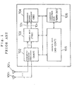
- Fig. 1 is a block diagram showing a configuration of a mobile station in such a cellular system.
- the mobile station comprises n antennas 101 1 to 101 n , transmit/receive amplifier (AMP) 102, radio unit (TRX) 103, baseband signal processor (BB) 104, control unit (MS-CONT) 105, and terminal interface unit (TERM-INT) 106.
- AMP transmit/receive amplifier
- TRX radio unit
- BB baseband signal processor
- MS-CONT control unit
- TX-INT terminal interface unit
- Antennas 101 1 to 101 n transmit an upward RF signal amplified at a transmission amplifier in transmit/receiver amplifier 102, and receives a downward RF signal from a base station and outputs the signal to transmit/receiver amplifier 102.
- Diversity reception is achieved by using n antennas 101 1 to 101 n .
- Transmit/receiver amplifier 102 is provided with a transmission amplifier for amplifying a transmission RF signal and a low noise amplifier for amplifying a reception RF signal, and demultiplexes the RF transmission signal and the RF reception signal for connection to antennas 101 1 to 101 n .
- Radio unit 103 converts a transmission signal which has been subjected to baseband spread from digital form to analog form and performs quadrature modulation for conversion to an RF signal, and performs quasi-synchronous detection and converts a signal received from transmit/receive amplifier 102 from analog form to digital form for transmission to baseband signal processing unit 104.
- Baseband signal processing unit 104 performs baseband signal processing such as error correction coding for transmission data, framing, data modulation, spread modulation, despread of a received signal, chip synchronization, error correction decoding, data demultiplexing, diversity handover combination function, reception level measuring function, and the like.
- Control unit 105 performs control of the entire mobile station.
- Terminal interface unit 106 has a function as an adapter for voice and various types of data, as well as a function as an interface to a handset and image/data terminals.
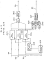
- Fig. 2 shows a configuration of a conventional CDMA communication device provided in baseband signal processing unit 104.
- the conventional CDMA communication device comprises n rake receivers 202 1 to 202 n , mixer 204, determinator 205, n Eb/N0 measuring units 306 1 to 306 n , transmission power control information generator 307, rake receiver control unit 208, and multipath searcher 209.
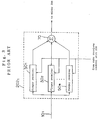
- rake receiver 202 1 includes m finger receivers 50 1 to 50 m and mixer 70. Since the configurations of rake receivers 202 2 to 202 n are similar to that of rake receiver 202 1 , the description thereof is omitted.
- Multipath searcher 209 acquires, from received signals 10 1 to 10 n , reception delay information which is information on delay times among respective paths contained in received signals 10 1 to 10 n .
- Rake receiver control unit 208 sets delay times for finger receivers 50 1 to 50 m in each of rake receivers 202 1 to 202 n based on the reception delay information acquired at multipath searcher 209.
- Rake receivers 202 1 to 202 n detects received signals 101 1 to 101 n , and output demodulated data which is the result of the detection. Specifically, finger receivers 50 1 to 50 m generate the demodulated data by individually demodulating received signal 10 1 for respective paths, delay the demodulated data using the delay time set by rake receiver control unit 208, and then output the data to mixer 70. Mixer 70 combines the demodulated data from finger receivers 50 1 to 50 m and outputs the combined data.
- Mixer 204 combines the demodulated data from rake receivers 202 1 to 202 n into one signal.
- Determinator 205 performs decoding with a determination of the signal combined by mixer 204 for output as decoded signal 20.
- Eb/N0 measuring units 306 1 to 306 n measure the Eb-N0s of the signals from rake receivers 202 1 to 202 n .
- Transmission power control information generator 307 sums the Eb/N0 measured at Eb/N0 measuring units 306 1 to 306 n to obtain the measurement result of the Eb/N0s, and generates transmission power control information 30 based on the measuring result of the Eb/N0s.
- Transmission power control information 30 is transmitted to the base station which is a transmitter through an upward channel, thereby performing transmission power control.
- received signals 10 1 to 10 n input thereto are sent to multipath searcher 209 which acquires reception delay information which is information on delay times among respective paths contained in received signals 10 1 to 10 n .
- Rake receiver control unit 208 sets delay times for finger receivers 50 1 to 50 m in each of rake receivers 202 1 to 202 n based on the reception delay information acquired at multipath searcher 209.
- Received signals 10 1 to 10 n demodulated and delayed by finger receivers 50 1 to 50 m are combined by mixer 70 as demodulated data after detection.
- Mixer 204 combines the demodulated data obtained at rake receivers 202 1 to 202 n into one signal.
- the demodulated data combined at mixer 204 is subjected to a determination at determinator 205, resulting in decoded signal 20.
- the demodulated data obtained at rake receivers 202 1 to 202 n are input to Eb/N0 measuring units 306 1 to 306 n for measuring the Eb/N0s of the respective demodulated data.
- Transmission power control information generator 307 derives the measuring result of the Eb/N0s by summing up the respective measured Eb/N0s, and generates transmission power control information 30 based on the obtained measuring result of the Eb/N0s.
- the measuring result of the Eb/N0s is obtained by measuring the Eb/N0s for respective rake receivers 202 1 to 202 n and summing up the measured Eb/N0s.
- the accuracy of the Eb/N0 measurement is deteriorated to cause the inability to perform stable transmission power control.
- the n demodulated data obtained from rake receivers 202 1 to 202 n are combined as they are. For this reason, in some reception states, the Eb/N0 of the demodulated data after the combination obtained by mixer 204 may not be higher than the Eb/N0 of the demodulated data before the combination.
- the CDMA communication device comprises means for weighting outputs from a plurality of rake receivers, respectively, and means for measuring the Eb/N0 after weighted signals are combined.
- the Eb/N0 of the demodulated data after combination is not deteriorated as compared with the Eb/N0 of the demodulated data before the combination.
- the Eb/N0 is measured using the demodulated data after the combination, the Eb/N0 can be measured with higher accuracy even under a deteriorated reception environment.
- the CDMA communication device further comprises means for weighting based on RSSI of an output from each rake receiver.
- the CDMA communication device further comprises means for controlling transmission power based on the measured Eb/N0.
- the CDMA communication device comprises means for weighting outputs from a plurality of rake receivers, and combines the weighted signals and controls transmission power based on the combined signal.
- the present invention performs transmission power control with the Eb/N0 derived using the demodulated data after the combination, more accurate transmission power control is possible to allow stable communication.
- the CDMA communication device comprises a plurality of rake receivers, a plurality of first weighting units, a first combining unit, and an Eb/N0 measuring unit.
- Each of the plurality of rake receivers demodulates a received signal for each path and combines the respective demodulated data after the respective data are delayed based on a delay time.
- the plurality of first weighting units weight the demodulated data after the combination output from the respective rake receivers.
- the first combining unit combines the signals weighted by the first weighting units.
- the Eb/N0 measuring unit measures an Eb/N0 of the demodulated data combined by the first combining unit.
- the CDMA communication device for decoding a plurality of received signals received at different antennas comprises a plurality of rake receivers, a multipath searcher, a rake receiver control unit, a plurality of first weighting units, a first combining unit, and an Eb/N0 measuring unit.
- Each of the receivers detects each of the received signals for each path, delays demodulated data which are the detection result based on a set delay time, and then combines and outputs the demodulated data.
- the multipath searcher acquires reception delay information which is information on delay times among respective paths contained in the received signals.
- the rake receiver control unit sets the delay time for the respective rake receivers based on the reception delay information acquired by the multipath searcher.
- the plurality of first weighting units weight the demodulated data output from the respective rake receivers.
- the first combining unit combines the signals weighted by the first weighting units into one signal.
- the Eb/N0 measuring unit measures an Eb/N0 of the demodulated data combined by the first combining unit.
- the present invention performs the Eb/N0 measurement with the demodulated data after the combination by the first combining unit, more accurate Eb/N0 measurement is possible even under a deteriorated reception environment.
- the present invention utilizes the first weighting units to weight the demodulated data from the respective rake receivers before the combination by the first combining unit.
- the Eb/N0 of the demodulated data after the combination is not deteriorated as compared with the Eb/N0 of the demodulated data before the combination.
- the Eb/N0 measurement with the demodulated data combined by the first combining unit requires only one Eb/N0 measuring unit, thereby allowing a simplified configuration of the CDMA communication device.
- each of the receivers includes a plurality of finger receivers, a plurality of second weighting units, and a second combining unit.
- the plurality of finger receivers generate demodulated data by individually demodulating a received signal for each path and then output the demodulated data after the demodulated data are delayed with delay time information contained in the received signal.
- the plurality of second weighting units weight the demodulated data output from the finger receivers, respectively.
- the second combining unit combines the demodulated data from the second weighting units and outputs the combined data.
- the second weighting units are provided between the respective finger receivers and the second combining unit, and weighting can also be performed individually for the demodulated data output from the respective finger receivers, thereby enabling estimation for each transmission path.
- the CDMA communication device further comprises means for controlling transmission power based on the Eb/N0 measured by the Eb/N0 measuring unit.
- the present invention controls transmission power with the Eb/N0 derived with the demodulated data after the combination, more accurate transmission power control is possible to allow stable communication.
- the CDMA communication device comprises a transmission power control information generator for generating transmission power control information which is information for controlling transmission power based on the Eb/N0 measured by the Eb/N0 measuring unit.
- the present invention generates the transmission power control information with the Eb/N0 derived using the demodulated data after the combination, thereby making it possible to perform more accurate transmission power control and stable communication.
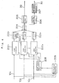
- a CDMA communication device of a first embodiment of the present invention is provided in baseband signal processing unit 104 of the CDMA cellular system shown in Fig. 1.
- the CDMA communication device comprises Eb/N0 measuring unit 206 and transmission power control information generator 207 instead of Eb/N0 measuring units 306 1 to 306 n and transmission power control information generator 307 in the conventional CDMA communication device shown in Fig. 2, and further comprises weighting units 203 1 to 203 n between rake receivers 202 1 to 202 n and mixer 204, respectively.
- Weighting units 203 1 to 203 n weight demodulated data output from rake receivers 202 1 to 202 n , respectively.
- a method of weighting is an optimal ratio combination method.
- the optimal ratio combination method determines weights for weighting units 203 1 to 203 n such that the demodulated data from respective rake receivers 202 1 to 202 n are combined at a ratio which leads to the maximum Eb/N0 of a signal after combination at mixer 204.
- Another weighting method is a method in which a weight is increased when an RSSI (Received Signal Strength Indicator) of demodulated data is high.
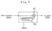
- Fig. 5 shows the configuration of weighting unit 203 1 when such weighting is performed.
- Weighting unit 203 1 comprises RSSI measuring unit 40 and multiplier 41 as shown in Fig. 5. Since the configurations of weighting units 203 2 to 203 n are similar to that of weighting unit 203 1 , the description thereof is omitted.
- RSSI measuring unit 40 measures the RSSI of the demodulated data from rake receiver 202 1 .
- Multiplier 41 multiplies the RSSI measured by RSSI measuring unit 40 by the demodulated data from rake receiver 202 1 .
- the RSSI is typically measured using a known symbol known to a receiver side. For example, a pilot symbol whose pattern can be known before reception at the receiver side is used.
- a pilot symbol whose pattern can be known before reception at the receiver side is used.
- W-CDMA Wide band CDMA
- four pilot symbols are included per slot.
- the RSSI can be obtained by deriving power per symbol from the total value of the power of the four symbols.
- Weighting units 203 1 to 203 n perform weighting such that a weight is increased when the RSSI of demodulated data from rake receivers 202 1 to 202 n is high, with the aforementioned operation.
- Eb/N0 measuring unit 206 measures the Eb/N0 of demodulated data after combination at mixer 204.
- Transmission power control information generator 207 generates transmission power control information 30 based on the measurement result of the Eb/N0 measured at Eb/N0 measuring unit 206.
- the operation to the generation of the demodulated data at respective rake receivers 202 1 to 202 n is similar to that of the conventional CDMA communication device shown in Fig. 2. The description thereof is thus omitted.
- the demodulated data from respective rake receivers 202 1 to 202 n are combined into one demodulated data by mixer 204 after the weighting at weighting units 203 1 to 203 n .
- Eb/N0 measuring unit 206 measures the Eb/N0 using the demodulated data after the combination.
- Transmission power control information generator 207 generates transmission power control information 30 using the result and sends the information.
- the demodulated data after the combination by mixer 204 exerts an Eb/N0 higher than those of the n demodulated data before the combination. Since the combination is performed after the weighting by weighting units 203 1 to 203 n , it is very unlikely that the Eb/N0 of the demodulated data after the combination is lower than the Eb/N0 of the demodulated data before the combination even in a deteriorated reception state such as fading.
- Transmission power control information 30 is generated with the Eb/N0 derived using the demodulated data after the combination to allow more accurate transmission power control, resulting in stable communication.
- Eb/N0 measuring units 306 1 to 306 n are required for respective rake receivers 202 1 to 202 n .
- only one Eb/N0 measuring unit 206 is required due to the Eb/N0 measurement of the demodulated data after the combination, thereby permitting a simplified configuration for a mobile station.
- the Eb/N0 can not be measured and the transmission power control information can not be obtained until after the rake/diversity combination.
- particular problems are not produced if a control delay is minimized by performing the rake/diversity combination, the Eb/N0 measurement, and the generation of the transmission power control information with the measured Eb/N0 in a period shorter than a transmission power control period.
- a CDMA communication device of a second embodiment of the present invention comprises rake receivers 302 1 to 302 n instead of rake receivers 202 1 to 202 n in the CDMA communication device shown in Fig. 4.
- rake receiver 302 1 differs from rake receiver 202 1 shown in Fig. 3 in that rake receiver 302 1 includes weighting units 60 1 to 60 m between finger receivers 50 1 to 50 m and adder 70, respectively. Since the configurations of rake receivers 302 2 to 302 n are similar to that of rake receiver 302 1 , the description thereof is omitted.
- Each of weighting units 60 1 to 60 m includes RSSI measuring unit 61 and multiplier 62.
- Weighting units 60 1 to 60 m have functions and operations similar to those of weighting units 203 1 to 203 n shown in Fig. 4, and the only difference between them is the position at which they are provided.
- the CDMA communication device of the embodiment has the effect of estimating each transmission path in addition to the effects in the aforementioned first embodiment since weighting units 60 1 to 60 m are provided for respective finger receivers 50 1 to 50 m .
- the aforementioned first and second embodiments perform the Eb/N0 measurement using the demodulated data after the combination to allow the Eb/N0 measurement with high accuracy even under a deteriorated reception environment, and the transmission power control is performed based on the measured Eb/N0.
- the present invention is not limited to the transmission power control and is similarly applicable to another control performed on the basis of the Eb/N0. With the aforementioned configuration, the control based on the Eb/N0 can be stably performed similarly to the transmission power control.
Landscapes
- Engineering & Computer Science (AREA)
- Computer Networks & Wireless Communication (AREA)
- Signal Processing (AREA)
- Quality & Reliability (AREA)
- Mobile Radio Communication Systems (AREA)
Abstract
Description
- The present invention relates to a digital car telephone and cellular phone system (cellular system) using a CDMA (Code Division Multiple Access) communication scheme, and more particularly to a CDMA communication device and a transmission power control method.
- In recent years, the CDMA communication scheme attracts attention as a communication method for use in mobile communication systems due to its resistance to interference and disturbance. The CDMA communication scheme refers to a communication scheme in which a transmitting side spreads a user signal to be transmitted with a spreading code and then transmits the signal, while a receiving side performs despread with the same code as that used by the transmitting side to obtain the original user signal.
- In the CDMA communication scheme, a plurality of transmitting sides perform spread with different spreading codes each having orthogonality, and a receiving side selects a spreading code for use in despread to allow each communication to be specified, thereby making it possible for a plurality of communications to use the same frequency band.
- However, since it is difficult to completely maintain the orthogonality among all the spreading codes being used, exact orthogonality is not obtained actually in the respective spreading codes, resulting in a correlational component between one code and another code. The correlational component serves as an interference component for the communication associated with the one code and contributes to deterioration of communication quality. Since the interference component is produced from such a factor, the interference component is increased as the number of the communications is increased.
- For this reason, there is a critical risk in that, when signal power from one mobile station is significantly higher than signal power from another mobile station at an antenna of a base station, the base station can not demodulate the signals other than the signal from the mobile station which produces the high received power, of a plurality of signals received at its antenna. The problem is widely known as a near-far problem in the CDMA communication scheme. In the CDMA cellular system, to solve the near-far problem, a TPC (Transmission Power Control) technique is essential in which the signal power from all transmitters at an input of a receiver is controlled to have the same magnitude.
- In the transmission power control, a receiver has a preset Eb/N0 (desired wave power density to noise power density ratio) serving as a reference and the receiver controls transmission power from each transmitter such that an Eb/N0 obtained from a communication of each transmitter is equal to the Eb/N0 reference value. More specifically, a downward channel for transmission from a base station to a mobile station includes a transmission power control signal for directing an increase or decrease in transmission power of the mobile station, which data is used by the base station to direct an increase or decrease in current transmission power to each mobile station. On the other hand, an upward channel for transmission from the mobile station to the base station includes a transmission power control signal for directing an increase or decrease in transmission power to the base station, which data is used by the mobile station to direct an increase or decrease in current transmission power to the base station.
- In the CDMA cellular system, a rake/diversity reception technique is also essential to high-quality reception under a multipath fading environment.
- Fig. 1 is a block diagram showing a configuration of a mobile station in such a cellular system.
- The mobile station comprises
n antennas 1011 to 101n, transmit/receive amplifier (AMP) 102, radio unit (TRX) 103, baseband signal processor (BB) 104, control unit (MS-CONT) 105, and terminal interface unit (TERM-INT) 106. -
Antennas 1011 to 101n transmit an upward RF signal amplified at a transmission amplifier in transmit/receiver amplifier 102, and receives a downward RF signal from a base station and outputs the signal to transmit/receiver amplifier 102. Diversity reception is achieved by usingn antennas 1011 to 101n. Transmit/receiver amplifier 102 is provided with a transmission amplifier for amplifying a transmission RF signal and a low noise amplifier for amplifying a reception RF signal, and demultiplexes the RF transmission signal and the RF reception signal for connection toantennas 1011 to 101n.Radio unit 103 converts a transmission signal which has been subjected to baseband spread from digital form to analog form and performs quadrature modulation for conversion to an RF signal, and performs quasi-synchronous detection and converts a signal received from transmit/receiveamplifier 102 from analog form to digital form for transmission to basebandsignal processing unit 104. - Baseband
signal processing unit 104 performs baseband signal processing such as error correction coding for transmission data, framing, data modulation, spread modulation, despread of a received signal, chip synchronization, error correction decoding, data demultiplexing, diversity handover combination function, reception level measuring function, and the like. -
Control unit 105 performs control of the entire mobile station.Terminal interface unit 106 has a function as an adapter for voice and various types of data, as well as a function as an interface to a handset and image/data terminals. - Next, Fig. 2 shows a configuration of a conventional CDMA communication device provided in baseband
signal processing unit 104. - The conventional CDMA communication device comprises n rake receivers 2021 to 202n,
mixer 204,determinator 205, n Eb/N0 measuring units 3061 to 306n, transmission powercontrol information generator 307, rakereceiver control unit 208, andmultipath searcher 209. - As shown in Fig. 3, rake receiver 2021 includes m finger receivers 501 to 50m and
mixer 70. Since the configurations of rake receivers 2022 to 202n are similar to that of rake receiver 2021, the description thereof is omitted. -
Multipath searcher 209 acquires, from receivedsignals 101 to 10n, reception delay information which is information on delay times among respective paths contained in receivedsignals 101 to 10n. Rakereceiver control unit 208 sets delay times for finger receivers 501 to 50m in each of rake receivers 2021 to 202n based on the reception delay information acquired atmultipath searcher 209. - Rake receivers 2021 to 202n detects received
signals 1011 to 101n, and output demodulated data which is the result of the detection. Specifically, finger receivers 501 to 50m generate the demodulated data by individually demodulating receivedsignal 101 for respective paths, delay the demodulated data using the delay time set by rakereceiver control unit 208, and then output the data to mixer 70.Mixer 70 combines the demodulated data from finger receivers 501 to 50m and outputs the combined data. -
Mixer 204 combines the demodulated data from rake receivers 2021 to 202n into one signal. Determinator 205 performs decoding with a determination of the signal combined bymixer 204 for output as decodedsignal 20. - Eb/N0 measuring units 3061 to 306n measure the Eb-N0s of the signals from rake receivers 2021 to 202n. Transmission power
control information generator 307 sums the Eb/N0 measured at Eb/N0 measuring units 3061 to 306n to obtain the measurement result of the Eb/N0s, and generates transmissionpower control information 30 based on the measuring result of the Eb/N0s. Transmissionpower control information 30 is transmitted to the base station which is a transmitter through an upward channel, thereby performing transmission power control. - Next, the operation of the conventional CDMA communication device is described. In the conventional CDMA communication device, received
signals 101 to 10n input thereto are sent tomultipath searcher 209 which acquires reception delay information which is information on delay times among respective paths contained in receivedsignals 101 to 10n. Rakereceiver control unit 208 sets delay times for finger receivers 501 to 50m in each of rake receivers 2021 to 202n based on the reception delay information acquired atmultipath searcher 209. Receivedsignals 101 to 10n demodulated and delayed by finger receivers 501 to 50m are combined bymixer 70 as demodulated data after detection. -
Mixer 204 combines the demodulated data obtained at rake receivers 2021 to 202n into one signal. The demodulated data combined atmixer 204 is subjected to a determination atdeterminator 205, resulting in decodedsignal 20. - The demodulated data obtained at rake receivers 2021 to 202n are input to Eb/N0 measuring units 3061 to 306n for measuring the Eb/N0s of the respective demodulated data. Transmission power
control information generator 307 derives the measuring result of the Eb/N0s by summing up the respective measured Eb/N0s, and generates transmissionpower control information 30 based on the obtained measuring result of the Eb/N0s. - In the mobile station in the conventional CDMA cellular system, the measuring result of the Eb/N0s is obtained by measuring the Eb/N0s for respective rake receivers 2021 to 202n and summing up the measured Eb/N0s. However, under an environment with fading, interference of another signal, reception of highly correlated signals associated with a reception delay, or the like, the accuracy of the Eb/N0 measurement, is deteriorated to cause the inability to perform stable transmission power control.
- Additionally, in the conventional CDMA cellular system, the n demodulated data obtained from rake receivers 2021 to 202n are combined as they are. For this reason, in some reception states, the Eb/N0 of the demodulated data after the combination obtained by
mixer 204 may not be higher than the Eb/N0 of the demodulated data before the combination. - It is an object of the present invention to provide a CDMA communication device and a transmission power control method thereof capable of performing stable transmission power control even in a deteriorated reception state.
- According to a first aspect of the present invention, the CDMA communication device comprises means for weighting outputs from a plurality of rake receivers, respectively, and means for measuring the Eb/N0 after weighted signals are combined.
- In the present invention, since demodulated data from the respective rake receivers are combined after the weighting, the Eb/N0 of the demodulated data after combination is not deteriorated as compared with the Eb/N0 of the demodulated data before the combination. In addition, since the Eb/N0 is measured using the demodulated data after the combination, the Eb/N0 can be measured with higher accuracy even under a deteriorated reception environment.
- In an embodiment of the present invention, the CDMA communication device further comprises means for weighting based on RSSI of an output from each rake receiver.
- In another embodiment of the present invention, the CDMA communication device further comprises means for controlling transmission power based on the measured Eb/N0.
- According to a second aspect of the present invention, the CDMA communication device comprises means for weighting outputs from a plurality of rake receivers, and combines the weighted signals and controls transmission power based on the combined signal.
- Since the present invention performs transmission power control with the Eb/N0 derived using the demodulated data after the combination, more accurate transmission power control is possible to allow stable communication.
- According to a third aspect of the present invention, the CDMA communication device comprises a plurality of rake receivers, a plurality of first weighting units, a first combining unit, and an Eb/N0 measuring unit.
- Each of the plurality of rake receivers demodulates a received signal for each path and combines the respective demodulated data after the respective data are delayed based on a delay time. The plurality of first weighting units weight the demodulated data after the combination output from the respective rake receivers. The first combining unit combines the signals weighted by the first weighting units. The Eb/N0 measuring unit measures an Eb/N0 of the demodulated data combined by the first combining unit.
- According to a fourth aspect of the present invention, the CDMA communication device for decoding a plurality of received signals received at different antennas comprises a plurality of rake receivers, a multipath searcher, a rake receiver control unit, a plurality of first weighting units, a first combining unit, and an Eb/N0 measuring unit.
- Each of the receivers detects each of the received signals for each path, delays demodulated data which are the detection result based on a set delay time, and then combines and outputs the demodulated data. The multipath searcher acquires reception delay information which is information on delay times among respective paths contained in the received signals. The rake receiver control unit sets the delay time for the respective rake receivers based on the reception delay information acquired by the multipath searcher. The plurality of first weighting units weight the demodulated data output from the respective rake receivers. The first combining unit combines the signals weighted by the first weighting units into one signal. The Eb/N0 measuring unit measures an Eb/N0 of the demodulated data combined by the first combining unit.
- Since the present invention performs the Eb/N0 measurement with the demodulated data after the combination by the first combining unit, more accurate Eb/N0 measurement is possible even under a deteriorated reception environment.
- In addition, the present invention utilizes the first weighting units to weight the demodulated data from the respective rake receivers before the combination by the first combining unit. Thus, the Eb/N0 of the demodulated data after the combination is not deteriorated as compared with the Eb/N0 of the demodulated data before the combination.
- Furthermore, in the present invention, the Eb/N0 measurement with the demodulated data combined by the first combining unit requires only one Eb/N0 measuring unit, thereby allowing a simplified configuration of the CDMA communication device.
- According to an embodiment of the present invention, each of the receivers includes a plurality of finger receivers, a plurality of second weighting units, and a second combining unit.
- The plurality of finger receivers generate demodulated data by individually demodulating a received signal for each path and then output the demodulated data after the demodulated data are delayed with delay time information contained in the received signal. The plurality of second weighting units weight the demodulated data output from the finger receivers, respectively. The second combining unit combines the demodulated data from the second weighting units and outputs the combined data.
- According to the present invention, the second weighting units are provided between the respective finger receivers and the second combining unit, and weighting can also be performed individually for the demodulated data output from the respective finger receivers, thereby enabling estimation for each transmission path.
- According to another embodiment of the present invention, the CDMA communication device further comprises means for controlling transmission power based on the Eb/N0 measured by the Eb/N0 measuring unit.
- Since the present invention controls transmission power with the Eb/N0 derived with the demodulated data after the combination, more accurate transmission power control is possible to allow stable communication.
- According to a fifth aspect of the present invention, the CDMA communication device comprises a transmission power control information generator for generating transmission power control information which is information for controlling transmission power based on the Eb/N0 measured by the Eb/N0 measuring unit.
- The present invention generates the transmission power control information with the Eb/N0 derived using the demodulated data after the combination, thereby making it possible to perform more accurate transmission power control and stable communication.
- The above and other object, features and advantages of the present invention will become apparent from the following description with reference to the accompanying drawings which illustrate examples of the present invention.
-
- Fig. 1 is a block diagram showing a configuration of a mobile station in a cellular system using the CDMA scheme;
- Fig. 2 is a block diagram showing a configuration of a conventional CDMA communication device;
- Fig. 3 is a block diagram showing the configuration of rake receiver 2021 in Fig. 2;
- Fig. 4 is a block diagram showing a configuration of a CDMA communication device of a first embodiment of the present invention;
- Fig. 5 is a block diagram showing the configuration
of
weighting unit 2031 in Fig. 4; - Fig. 6 is a block diagram showing a configuration of a CDMA communication device of a second embodiment of the present invention; and
- Fig. 7 is a block diagram showing the configuration of rake receiver 3021 in Fig. 5.
-
- Referring to Fig. 4, a CDMA communication device of a first embodiment of the present invention is provided in baseband
signal processing unit 104 of the CDMA cellular system shown in Fig. 1. The CDMA communication device comprises Eb/N0 measuring unit 206 and transmission powercontrol information generator 207 instead of Eb/N0 measuring units 3061 to 306n and transmission powercontrol information generator 307 in the conventional CDMA communication device shown in Fig. 2, and further comprisesweighting units 2031 to 203n between rake receivers 2021 to 202n andmixer 204, respectively. -
Weighting units 2031 to 203n weight demodulated data output from rake receivers 2021 to 202n, respectively. - A method of weighting is an optimal ratio combination method. The optimal ratio combination method determines weights for
weighting units 2031 to 203n such that the demodulated data from respective rake receivers 2021 to 202n are combined at a ratio which leads to the maximum Eb/N0 of a signal after combination atmixer 204. - Another weighting method is a method in which a weight is increased when an RSSI (Received Signal Strength Indicator) of demodulated data is high. Fig. 5 shows the configuration of
weighting unit 2031 when such weighting is performed. -
Weighting unit 2031 comprisesRSSI measuring unit 40 andmultiplier 41 as shown in Fig. 5. Since the configurations ofweighting units 2032 to 203n are similar to that ofweighting unit 2031, the description thereof is omitted. -
RSSI measuring unit 40 measures the RSSI of the demodulated data from rake receiver 2021.Multiplier 41 multiplies the RSSI measured byRSSI measuring unit 40 by the demodulated data from rake receiver 2021. - The RSSI is typically measured using a known symbol known to a receiver side. For example, a pilot symbol whose pattern can be known before reception at the receiver side is used. In a W-CDMA (Wide band CDMA) which is one of standards for the CDMA communication system, four pilot symbols are included per slot. The RSSI can be obtained by deriving power per symbol from the total value of the power of the four symbols.
-
Weighting units 2031 to 203n perform weighting such that a weight is increased when the RSSI of demodulated data from rake receivers 2021 to 202n is high, with the aforementioned operation. - Eb/
N0 measuring unit 206 measures the Eb/N0 of demodulated data after combination atmixer 204. Transmission powercontrol information generator 207 generates transmissionpower control information 30 based on the measurement result of the Eb/N0 measured at Eb/N0 measuring unit 206. - Next, the operation of the CDMA communication device in the embodiment is detailed in detail with reference to Fig. 4.
- In the CDMA communication device in the embodiment, the operation to the generation of the demodulated data at respective rake receivers 2021 to 202n is similar to that of the conventional CDMA communication device shown in Fig. 2. The description thereof is thus omitted.
- The demodulated data from respective rake receivers 2021 to 202n are combined into one demodulated data by
mixer 204 after the weighting atweighting units 2031 to 203n. Eb/N0 measuring unit 206 measures the Eb/N0 using the demodulated data after the combination. Transmission powercontrol information generator 207 generates transmissionpower control information 30 using the result and sends the information. - The demodulated data after the combination by
mixer 204 exerts an Eb/N0 higher than those of the n demodulated data before the combination. Since the combination is performed after the weighting byweighting units 2031 to 203n, it is very unlikely that the Eb/N0 of the demodulated data after the combination is lower than the Eb/N0 of the demodulated data before the combination even in a deteriorated reception state such as fading. - The configuration as in the embodiment in which the Eb/N0 is measured using the demodulated data after the combination enables Eb/N0 measurement with higher accuracy even under a deteriorated reception environment as mentioned above. Transmission
power control information 30 is generated with the Eb/N0 derived using the demodulated data after the combination to allow more accurate transmission power control, resulting in stable communication. - In the conventional CDMA communication device shown in Fig. 2, Eb/N0 measuring units 3061 to 306n are required for respective rake receivers 2021 to 202n. However, according to the CDMA communication device of the embodiment, only one Eb/
N0 measuring unit 206 is required due to the Eb/N0 measurement of the demodulated data after the combination, thereby permitting a simplified configuration for a mobile station. - In the embodiment, the Eb/N0 can not be measured and the transmission power control information can not be obtained until after the rake/diversity combination. However, particular problems are not produced if a control delay is minimized by performing the rake/diversity combination, the Eb/N0 measurement, and the generation of the transmission power control information with the measured Eb/N0 in a period shorter than a transmission power control period.
- Referring to Fig. 6, a CDMA communication device of a second embodiment of the present invention comprises rake receivers 3021 to 302n instead of rake receivers 2021 to 202n in the CDMA communication device shown in Fig. 4.
- As shown in Fig. 7, rake receiver 3021 differs from rake receiver 2021 shown in Fig. 3 in that rake receiver 3021 includes
weighting units 601 to 60m between finger receivers 501 to 50m andadder 70, respectively. Since the configurations of rake receivers 3022 to 302n are similar to that of rake receiver 3021, the description thereof is omitted. - Each of
weighting units 601 to 60m includesRSSI measuring unit 61 andmultiplier 62.Weighting units 601 to 60m have functions and operations similar to those ofweighting units 2031 to 203n shown in Fig. 4, and the only difference between them is the position at which they are provided. - The CDMA communication device of the embodiment has the effect of estimating each transmission path in addition to the effects in the aforementioned first embodiment since
weighting units 601 to 60m are provided for respective finger receivers 501 to 50m. - While the aforementioned first and second embodiments have been described with the examples in which the present invention is applied to a mobile station, the present invention is not limited thereto and is similarly applicable to a base station of the CDMA cellular system, for example.
- In addition, the aforementioned first and second embodiments perform the Eb/N0 measurement using the demodulated data after the combination to allow the Eb/N0 measurement with high accuracy even under a deteriorated reception environment, and the transmission power control is performed based on the measured Eb/N0. However, the present invention is not limited to the transmission power control and is similarly applicable to another control performed on the basis of the Eb/N0. With the aforementioned configuration, the control based on the Eb/N0 can be stably performed similarly to the transmission power control.
- While preferred embodiments of the present have been described using specific terms, such description is for illustrative purposes only, and it is to be understood that changes and variations may be made without departing from the spirit or scope of the following claims.
Claims (20)
- A CDMA communication device comprising:means for weighting outputs from a plurality of rake receivers respectively; andmeans for measuring an Eb/N0 after the weighted signals are combined.
- The CDMA communication device according to claim 1, further comprising means for controlling transmission power based on said measured Eb/N0.
- The CDMA communication device according to claim 1, wherein said means for weighting performs weighting based on an RSSI of an output from each of said rake receivers.
- The CDMA communication device according to claim 3, further comprising means for controlling transmission power based on said measured Eb/N0.
- A CDMA communication device comprising:means for weighting outputs from a plurality of rake receivers respectively; andmeans for combining weighted signals into one signal to control transmission power based on the signal after the combination.
- A CDMA communication device comprising:a plurality of rake receivers, each of said receivers for demodulating a received signal for each path and combining the respective demodulated data after the respective data are delayed based on a delay time;a plurality of first weighting means, each of said first weighting means for weighting the demodulated data after the combination output from each of said plurality of rake receivers;a first combining means for combining the signals weighted by said plurality of first weighting means; andan Eb/N0 measuring means for measuring an Eb/N0 of the demodulated data combined by said first combining means.
- The CDMA communication device according to claim 6, wherein each of said first weighting means includes a first RSSI measuring means for measuring an RSSI of the demodulated data from each of said rake receivers, and weights the demodulated data from said rake receiver based on the RSSI measured by said first RSSI measuring means.
- The CDMA communication device according to claim 6, wherein each of said first weighting means includes a first RSSI measuring means for measuring an RSSI of the demodulated data from each of said rake receivers, and a first multiplier for multiplying the RSSI measured by said first RSSI measuring means by the demodulated data from said rake receiver.
- A CDMA communication device for decoding a plurality of received signals received at different antennas, comprising:a plurality of rake receivers, each of said receivers for detecting each of said received signals for each path, delaying demodulated data which are the detection result based on a set delay time, and then combining and outputting the demodulated data;a multipath searcher for acquiring reception delay information which is information on a delay time among respective paths contained in said received signals;a rake receiver control means for setting the delay time for said rake receivers respectively based on the reception delay information acquired by said multipath searcher;a plurality of first weighting means, each of said first weighting means for weighting the demodulated data output from each of said rake receivers;a first combining means for combining the signals weighted by said first weighting means into one signal; andan Eb/N0 measuring means for measuring an Eb/N0 of the demodulated data combined by said first combining means.
- The CDMA communication device according to claim 9, wherein each of said first weighting means includes a first RSSI measuring means for measuring an RSSI of the demodulated data from each of said rake receivers, and weights the demodulated data from said rake receiver based on the RSSI measured by said first RSSI measuring means.
- The CDMA communication device according to claim 9, wherein each of said first weighting means includes a first RSSI measuring means for measuring an RSSI of the demodulated data from each of said rake receivers, and a first multiplier for multiplying the RSSI measured by said first RSSI measuring means by the demodulated data from said rake receiver.
- The CDMA communication device according to claim 5, wherein each of said receivers includes:a plurality of finger receivers for individually demodulating a received signal for each path to generate the demodulated data, and for delaying the demodulated data with delay time information contained in said received signal to output the demodulated data;a plurality of second weighting means for weighting the demodulated data output from said finger receivers, respectively; anda second combining means for combining the demodulated data from said second weighting means and outputting the combined data.
- The CDMA communication device according to claim 12, wherein each of said second weighting means includes a second RSSI measuring means for measuring an RSSI of the demodulated data from each of said finger receivers, and weights the demodulated data from said finger receiver based on the RSSI measured by said second RSSI measuring means.
- The CDMA communication device according to claim 12, wherein each of said second weighting means, and a second RSSI measuring means for measuring an RSSI of the demodulated data from each of said finger receivers, and includes a second multiplier for multiplying the RSSI measured by said second RSSI measuring means by the demodulated data from said finger receiver.
- The CDMA communication device according to claim 6, further comprising means for controlling transmission power based on the Eb/N0 measured by said Eb/N0 measuring means.
- The CDMA communication device according to claim 6, further comprising a transmission power control information generator for generating transmission power control information which is information for controlling transmission power based on the Eb/N0 measured by said Eb/N0 measuring means.
- A method of controlling transmission power for producing transmission power control information for controlling transmission power with a plurality of received signals received at different antennas, said method comprising the steps of:detecting each of said received signals for each path, delaying demodulated data which are the detection result based on a set delay time, and then combining the demodulated data to produce demodulated data;acquiring reception delay information which is information on a delay time among respective paths contained in said received signals;setting said delay time based on said acquired reception delay information;weighting said demodulated data respectively and then combining the data into one demodulated data;
andmeasuring an Eb/N0 of the demodulated data after the combination and producing said transmission power control information based on said measured Eb/N0. - The method of controlling transmission power according to claim 17, wherein said step of weighting said demodulated data includes measuring an RSSI of each of said demodulated data and multiplying said measured RSSI by said demodulated data.
- A method of controlling transmission power for producing transmission power control information for controlling transmission power with a plurality of received signals received at different antennas, comprising the steps of:detecting each of said received signals for each path, delaying demodulated data which are the detection result based on a set delay time, weighting the demodulated data, and then combining the demodulated data to produce demodulated data;acquiring reception delay information which is information on a delay time among respective paths contained in said received signals;setting said delay time based on said acquired reception delay information;weighting said demodulated data respectively and then combining the data into one demodulated data;
andmeasuring an Eb/N0 of the demodulated data after the combination and producing said transmission power control information based on said measured Eb/N0. - The method of controlling transmission power according to claim 19, wherein said step of weighting said demodulated data includes measuring an RSSI of each of said demodulated data and multiplying said measured RSSI by said demodulated data.
Applications Claiming Priority (2)
| Application Number | Priority Date | Filing Date | Title |
|---|---|---|---|
| JP18923899A JP2001024555A (en) | 1999-07-02 | 1999-07-02 | Cdma communication device and control of transmission power |
| JP18923899 | 1999-07-02 |
Publications (2)
| Publication Number | Publication Date |
|---|---|
| EP1065802A1 true EP1065802A1 (en) | 2001-01-03 |
| EP1065802B1 EP1065802B1 (en) | 2005-08-31 |
Family
ID=16237932
Family Applications (1)
| Application Number | Title | Priority Date | Filing Date |
|---|---|---|---|
| EP00113809A Expired - Lifetime EP1065802B1 (en) | 1999-07-02 | 2000-06-29 | Transmission power control method and apparatus by measuring the Eb/No of a weighted signals' combination |
Country Status (6)
| Country | Link |
|---|---|
| US (1) | US6724808B1 (en) |
| EP (1) | EP1065802B1 (en) |
| JP (1) | JP2001024555A (en) |
| CN (1) | CN1118978C (en) |
| AU (1) | AU771784B2 (en) |
| DE (1) | DE60022270T2 (en) |
Cited By (1)
| Publication number | Priority date | Publication date | Assignee | Title |
|---|---|---|---|---|
| WO2005055467A1 (en) * | 2003-12-05 | 2005-06-16 | Koninklijke Philips Electronics N.V. | A 2d rake receiver for use in wireless communication systems |
Families Citing this family (8)
| Publication number | Priority date | Publication date | Assignee | Title |
|---|---|---|---|---|
| JP3308962B2 (en) * | 2000-03-28 | 2002-07-29 | 松下電器産業株式会社 | Wireless receiving device and wireless receiving method |
| US7313398B1 (en) * | 2002-08-06 | 2007-12-25 | Sprint Spectrum L.P. | System and method for handoff in a CDMA network |
| US7154938B2 (en) * | 2002-12-31 | 2006-12-26 | Itron, Inc. | RF communications system utilizing digital modulation to transmit and receive data |
| US20050281361A1 (en) * | 2004-06-16 | 2005-12-22 | Broadcom Corporation | Interference cancellation of STBC with multiple streams in OFDM for wlan |
| US9225386B2 (en) * | 2007-11-20 | 2015-12-29 | Sony Corporation | Method for placement of fingers with G-Rake advanced receiver |
| WO2014054170A1 (en) * | 2012-10-05 | 2014-04-10 | 三菱電機株式会社 | Automotive wireless communication apparatus and wireless device |
| US10707917B2 (en) * | 2017-11-08 | 2020-07-07 | Viavi Solutions, Inc. | Instrument, system, and method for locating a leakage source |
| EP4635930A1 (en) | 2024-04-15 | 2025-10-22 | Holcim Technology Ltd | Low carbon solidifying composition with enhanced mechanical properties |
Citations (3)
| Publication number | Priority date | Publication date | Assignee | Title |
|---|---|---|---|---|
| US5812542A (en) * | 1996-03-18 | 1998-09-22 | Motorola, Inc. | Method for determining weighting coefficients in a CDMA radio receiver |
| US5881057A (en) * | 1995-09-13 | 1999-03-09 | Nec Corporation | Synchronous detector with reduced error computation for maximal-ratio combining |
| WO1999017466A1 (en) * | 1997-09-29 | 1999-04-08 | Qualcomm Incorporated | Using multiple antennas to mitigate specular reflection |
Family Cites Families (15)
| Publication number | Priority date | Publication date | Assignee | Title |
|---|---|---|---|---|
| JPH08265217A (en) | 1995-03-20 | 1996-10-11 | Nippon Telegr & Teleph Corp <Ntt> | Radio station equipment for spread spectrum communication |
| JPH0918400A (en) | 1995-06-30 | 1997-01-17 | Sanyo Electric Co Ltd | Diversity equipment |
| JP3212019B2 (en) | 1996-05-20 | 2001-09-25 | 株式会社エヌ・ティ・ティ・ドコモ | Transmission power control method in CDMA mobile communication system and CDMA mobile communication system |
| JP3001040B2 (en) | 1996-09-20 | 2000-01-17 | 日本電気株式会社 | Closed loop transmitter power control unit for CDMA cellular system |
| JPH10190526A (en) | 1996-12-26 | 1998-07-21 | Sony Corp | Receiving device and receiving method, and terminal device of wireless system |
| JPH10256969A (en) | 1997-03-11 | 1998-09-25 | Matsushita Electric Ind Co Ltd | Wireless base station device |
| JP2853705B2 (en) | 1997-05-07 | 1999-02-03 | 日本電気株式会社 | Spread spectrum communication receiver |
| JP2954086B2 (en) | 1997-05-16 | 1999-09-27 | 埼玉日本電気株式会社 | Mobile communication system |
| US6067315A (en) * | 1997-12-04 | 2000-05-23 | Telefonaktiebolaget Lm Ericsson | Method and apparatus for coherently-averaged power estimation |
| JP3305639B2 (en) * | 1997-12-24 | 2002-07-24 | 株式会社エヌ・ティ・ティ・ドコモ | RAKE receiver in direct spread CDMA transmission system |
| US6125109A (en) * | 1998-02-24 | 2000-09-26 | Repeater Technologies | Delay combiner system for CDMA repeaters and low noise amplifiers |
| JPH11266180A (en) * | 1998-03-18 | 1999-09-28 | Fujitsu Ltd | Array antenna system for wireless base station |
| US6456849B1 (en) * | 1998-07-31 | 2002-09-24 | Nokia Corporation | Apparatus and associated method, for allocating resources in a radio communication system to perform a communication service |
| US6370183B1 (en) * | 1998-10-26 | 2002-04-09 | Nortel Networks Limited | Predictive rake receiver for CDMA mobile radio systems |
| US6470044B1 (en) * | 1999-01-15 | 2002-10-22 | Sharp Laboratories Of America, Inc. | Computationally parsimonious forward link receiver for DS-CDMA systems and method for same |
-
1999
- 1999-07-02 JP JP18923899A patent/JP2001024555A/en active Pending
-
2000
- 2000-06-28 AU AU42738/00A patent/AU771784B2/en not_active Ceased
- 2000-06-29 EP EP00113809A patent/EP1065802B1/en not_active Expired - Lifetime
- 2000-06-29 DE DE2000622270 patent/DE60022270T2/en not_active Expired - Lifetime
- 2000-06-29 US US09/607,145 patent/US6724808B1/en not_active Expired - Lifetime
- 2000-07-03 CN CN00109560A patent/CN1118978C/en not_active Expired - Fee Related
Patent Citations (3)
| Publication number | Priority date | Publication date | Assignee | Title |
|---|---|---|---|---|
| US5881057A (en) * | 1995-09-13 | 1999-03-09 | Nec Corporation | Synchronous detector with reduced error computation for maximal-ratio combining |
| US5812542A (en) * | 1996-03-18 | 1998-09-22 | Motorola, Inc. | Method for determining weighting coefficients in a CDMA radio receiver |
| WO1999017466A1 (en) * | 1997-09-29 | 1999-04-08 | Qualcomm Incorporated | Using multiple antennas to mitigate specular reflection |
Cited By (1)
| Publication number | Priority date | Publication date | Assignee | Title |
|---|---|---|---|---|
| WO2005055467A1 (en) * | 2003-12-05 | 2005-06-16 | Koninklijke Philips Electronics N.V. | A 2d rake receiver for use in wireless communication systems |
Also Published As
| Publication number | Publication date |
|---|---|
| AU4273800A (en) | 2001-01-04 |
| US6724808B1 (en) | 2004-04-20 |
| JP2001024555A (en) | 2001-01-26 |
| CN1279546A (en) | 2001-01-10 |
| EP1065802B1 (en) | 2005-08-31 |
| CN1118978C (en) | 2003-08-20 |
| AU771784B2 (en) | 2004-04-01 |
| DE60022270D1 (en) | 2005-10-06 |
| DE60022270T2 (en) | 2006-06-29 |
Similar Documents
| Publication | Publication Date | Title |
|---|---|---|
| US6414948B1 (en) | Electric power controlling system for variable bit rate CDMA transmission and mobile telephone system | |
| US5799005A (en) | System and method for determining received pilot power and path loss in a CDMA communication system | |
| EP1062742B1 (en) | Correction of signal-interference ratio measures | |
| JP2937994B1 (en) | Cellular system, mobile portable device, base station device, and optimal path detection method and device | |
| JP3967472B2 (en) | CDMA receiver | |
| EP1214809B1 (en) | Method and system for measuring and adjusting the quality of an orthogonal transmit diversity signal | |
| JPH09252266A (en) | CDMA cellular radio transmission device | |
| KR100934832B1 (en) | Mobile communication system, mobile terminal in mobile communication system, control program thereof, and synchronization establishment determination method in mobile communication system | |
| KR100435795B1 (en) | Radio base station device and radio communication method | |
| US6724808B1 (en) | Transmission power control method of measuring Eb/N0 after weighted signals are combined | |
| JP2003046422A (en) | Mobile communication method for base station, mobile communication base station device and mobile station device | |
| JP2001326586A (en) | Cdma communication system and channel estimate method used for it | |
| EP1298814A2 (en) | CDMA receiver and channel estimation method | |
| EP0924875B1 (en) | Diversity reception method and apparatus in a CDMA system | |
| JP3474826B2 (en) | Receiving level measuring method and receiving level measuring circuit | |
| US6895038B2 (en) | Communication system | |
| JP3297654B2 (en) | CDMA radio receiving apparatus and CDMA radio receiving method | |
| JP3628247B2 (en) | Signal demodulation method and receiving apparatus | |
| EP1146668A1 (en) | Communication terminal, base station system, and method of controlling transmission power | |
| JP4084058B2 (en) | Receive level measurement circuit | |
| JP2003304177A (en) | Wireless receiving method and communication terminal device | |
| JP4266826B2 (en) | Data transmission method and receiver | |
| JPH112651A (en) | Signal power ratio estimator | |
| WO2005006595A1 (en) | Radio reception method and communication terminal device | |
| JP2005328355A (en) | Communication equipment |
Legal Events
| Date | Code | Title | Description |
|---|---|---|---|
| PUAI | Public reference made under article 153(3) epc to a published international application that has entered the european phase |
Free format text: ORIGINAL CODE: 0009012 |
|
| 17P | Request for examination filed |
Effective date: 20001108 |
|
| AK | Designated contracting states |
Kind code of ref document: A1 Designated state(s): DE FR GB IT |
|
| AX | Request for extension of the european patent |
Free format text: AL;LT;LV;MK;RO;SI |
|
| AKX | Designation fees paid |
Free format text: DE FR GB IT |
|
| 17Q | First examination report despatched |
Effective date: 20030408 |
|
| RTI1 | Title (correction) |
Free format text: TRANSMISSION POWER CONTROL METHOD AND APPARATUS BY MEASURING THE EB/NO OF A WEIGHTED SIGNALS' COMBINATION |
|
| GRAP | Despatch of communication of intention to grant a patent |
Free format text: ORIGINAL CODE: EPIDOSNIGR1 |
|
| GRAS | Grant fee paid |
Free format text: ORIGINAL CODE: EPIDOSNIGR3 |
|
| GRAA | (expected) grant |
Free format text: ORIGINAL CODE: 0009210 |
|
| AK | Designated contracting states |
Kind code of ref document: B1 Designated state(s): DE FR GB IT |
|
| REG | Reference to a national code |
Ref country code: GB Ref legal event code: FG4D |
|
| REF | Corresponds to: |
Ref document number: 60022270 Country of ref document: DE Date of ref document: 20051006 Kind code of ref document: P |
|
| ET | Fr: translation filed | ||
| PLBE | No opposition filed within time limit |
Free format text: ORIGINAL CODE: 0009261 |
|
| STAA | Information on the status of an ep patent application or granted ep patent |
Free format text: STATUS: NO OPPOSITION FILED WITHIN TIME LIMIT |
|
| 26N | No opposition filed |
Effective date: 20060601 |
|
| REG | Reference to a national code |
Ref country code: GB Ref legal event code: 732E Free format text: REGISTERED BETWEEN 20141023 AND 20141029 |
|
| REG | Reference to a national code |
Ref country code: FR Ref legal event code: TP Owner name: LENOVO INNOVATIONS LIMITED (HONG KONG), HK Effective date: 20141119 |
|
| REG | Reference to a national code |
Ref country code: FR Ref legal event code: PLFP Year of fee payment: 17 |
|
| PGFP | Annual fee paid to national office [announced via postgrant information from national office to epo] |
Ref country code: FR Payment date: 20160516 Year of fee payment: 17 |
|
| PGFP | Annual fee paid to national office [announced via postgrant information from national office to epo] |
Ref country code: IT Payment date: 20160621 Year of fee payment: 17 |
|
| REG | Reference to a national code |
Ref country code: FR Ref legal event code: ST Effective date: 20180228 |
|
| REG | Reference to a national code |
Ref country code: DE Ref legal event code: R082 Ref document number: 60022270 Country of ref document: DE Representative=s name: SPLANEMANN BARONETZKY KNITTER PATENTANWAELTE R, DE Ref country code: DE Ref legal event code: R081 Ref document number: 60022270 Country of ref document: DE Owner name: LENOVO INNOVATIONS LIMITED, HK Free format text: FORMER OWNER: NEC CORP., TOKYO, JP |
|
| PG25 | Lapsed in a contracting state [announced via postgrant information from national office to epo] |
Ref country code: IT Free format text: LAPSE BECAUSE OF NON-PAYMENT OF DUE FEES Effective date: 20170629 Ref country code: FR Free format text: LAPSE BECAUSE OF NON-PAYMENT OF DUE FEES Effective date: 20170630 |
|
| PGFP | Annual fee paid to national office [announced via postgrant information from national office to epo] |
Ref country code: GB Payment date: 20190627 Year of fee payment: 20 Ref country code: DE Payment date: 20190628 Year of fee payment: 20 |
|
| REG | Reference to a national code |
Ref country code: DE Ref legal event code: R071 Ref document number: 60022270 Country of ref document: DE |
|
| REG | Reference to a national code |
Ref country code: GB Ref legal event code: PE20 Expiry date: 20200628 |
|
| PG25 | Lapsed in a contracting state [announced via postgrant information from national office to epo] |
Ref country code: GB Free format text: LAPSE BECAUSE OF EXPIRATION OF PROTECTION Effective date: 20200628 |